DOI: 10.12928/TELKOMNIKA.v11i4.1484 653
A Design Study of Dual-Stator Permanent Magnet
Brushless DC Motor
Wang Yaling*1, Xu Yanliang2
School of Electrical Engineering, Shandong University
Jingshi Road No.17923, Jinan, Shandong, China, Ph.: 0086-0531-81696170 *Corresponding author, e-mail: [email protected], [email protected]
Abstrak
Motor DC brushless magnet permanen dengan stator ganda (DSBLDC) memiliki efisiensi dan torsi yang tinggi. Dengan kemampuannya untuk beroperasi pada berbagai keadaan yang ada pada berbagai mode sambungan belitan, menjadikannya sesuai untuk penggerak kendaran listrik. Namun demikian, struktur stator ganda yang dimilikinya menyebabkan motor ini sukar didesain dengan menggunakan metode desain yang telah ada. Paper ini menunjukkan bagaimana sebuah DSBLDC dengan struktur magnetik seri dapat dianggap sebagai dua motor DC brushless yang independen, yang terdiri atas motor DC brushless rotor dalam dan motor DC rotor luar. Jadi, sebuah DSBLDC dapat dibagi menjadi dua motor DC brushless stator tunggal. Berdasarkan paparan ini, metode desain dapat diverifikasi dengan analisis finite elemen (FEA), dan diperoleh langkah-langkah desain dasar. Lebih jauh lagi, melalui hasil percobaan motor yang diperoleh bukti kebenaran metode ini, selain itu juga diperoleh indikasi bahwa motor yang diperoleh memiliki kinerja yang lebih baik untuk digunakan pada kendaraan listrik.
Kata kunci: analisis finite elemen, desain rangkaian magnetik, kendaraan listrik, motor DC brushless stator ganda (DSBLDC)
Abstract
Dual-stator permanent magnet brushless DC Motor (DSBLDC) features high efficiency and torque-density. As DSBLDC could operate in various states according to different winding connection modes, it is fully qualified for electric vehicle (EV) drive. Unfortunately, due to the particular dual-stator structure, this kind of motor is difficult to be designed by available design methods. However, this paper demonstrates that a DSBLDC with series magnetic circuit structure can be regarded as being consisted of two independent BLDCs, an inner-rotor BLDC and an outer-rotor BLDC. Thus, the DSBLDC can be divided into two single-stator BLDCs.Based on this demonstration, the design method is verified by finite element analysis (FEA), and the basic design steps are given. Furthermore, experimental results of the prototype motor have verified the correction of the method, which also indicates that the motor with superior performance is adapted to EV drive.
Keywords: dual-stator permanent magnet brushless DC Motor (DSBLDC), electric vehicle drive, finite element analysis, magnetic circuit design
1. Introduction
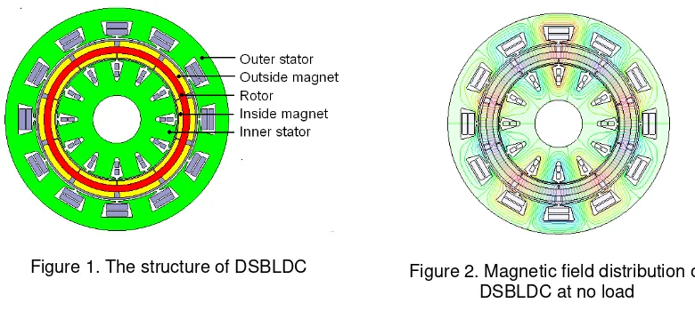
Figure 1. The structure of DSBLDC Figure 2. Magnetic field distribution of DSBLDC at no load
In this paper, a design method of DSBLDC with series magnetic circuit structure is proposed, i.e. a DSBLDC can be regarded as being consisted of an inner-rotor BLDC and an outer-rotor BLDC. Verified by FEA, it can be indicated that the proposed design method is practical. Moreover, a prototype motor designed by this method is manufactured and tested, and the experimental results of this prototype motor operating under various winding connection modes show excellent performance for EV drive.
2. Design Method and Steps
In Figure 1, the DSBLDC can be approximately treated as two BLDCs, i.e. the inner stator and the inside magnets compose an outer-rotor BLDC; the outer stator and the outside magnets compose an inner-rotor BLDC; both of the motors share the same rotor core. Due to the series magnetic circuit structure of the DSBLDC, the inside and outside magnets are oriented in the same magnetization direction and there is few flux in the rotor-yoke circumferential direction. It means that the rotor-yoke of the DSBLDC can be designed as thin as possible, whose thickness only depends on the mechanical strength of its material. Furthermore, the main flux per pole of the DSBLDC goes through two-layer airgaps, and the mutual inductance between the inner and outer stator windings can be neglected, which means that the coupling between the inner and outer stator windings can not be taken into account in the method,
Figure 3. The structure and magnetic field distribution of the inner motor at no load
Figure 4. The structure and magnetic field distribution of the outer motor at no load
As the inner and outer stator windings of the DSBLDC can be connected in series and supplied by one inverter, both of the BLDCs areconstrained as Equation 1.
The basic design steps are shown as follows:
1) It’s essential to specify a large group of combinations of inner and outer motors that satisfy the constraint (1),then these motor projects are designed by conventional design methods and softwares.
2) According to the design requirements of the DSBLDC, these projects are adjusted, guaranteeing that the combinations not only satisfy the constraint (1) but also satisfy the conventional motor design principles such as suitable slot fill factor, flux density, thermal load, etc. Thus, an appropriate combination of inner and outer motors can be obtained. 3) Apply the combination of the inner and outer motors to constitute the DSBLDC.
diameters of inner stator (mm) 36 90 diameters of outer stator (mm) 123.2 168 Length and thickness of middle rotor (mm) 55 5 Pole-arc coefficient of magnets 0.98 0.9 Numbers of stator slots 12 12
Winding pitch 1 1
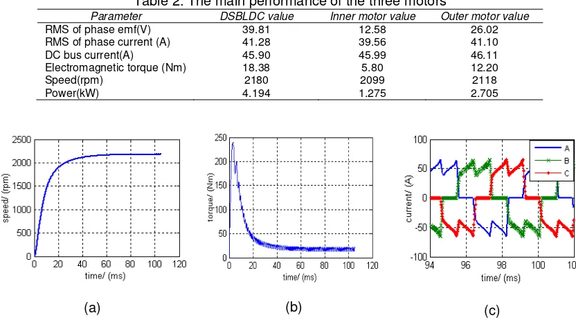
In the FEA, the DSBLDC is applied its rated load, and the inner and outer stator windings are connected in series and applied the whole voltage 98Vdc. And the inner and outer motors are respectively applied their rated loads and their rated voltages of 33Vdc and 65Vdc. The performances of the three motors obtained by FEA are listed in Table 2, and the waveforms are shown in Figure 5-7. Obviously, the performances composition of the inner and outer motors are generally consistent with those of the DSBLDC. And the electromagnetic torque of the DSBLDC is a supraposition of the torques in the dual airgaps, which permits the motor starting rapidly.
Table 2. The main performance of the three motors
Parameter DSBLDC value Inner motor value Outer motor value
RMS of phase emf(V) 39.81 12.58 26.02 RMS of phase current (A) 41.28 39.56 41.10 DC bus current(A) 45.90 45.99 46.11 Electromagnetic torque (Nm) 18.38 5.80 12.20
Speed(rpm) 2180 2099 2118
Power(kW) 4.194 1.275 2.705
(a) (b) (c)
Figure 5. The FEA waveforms of the DSBLDC, (a) Speed, (b) Electromagnetic torque, (c) Steady-state current
(a) (b) (c)
Figure 6. The FEA waveforms of the inner motor, (a) Speed, (b) Electromagnetic torque, (c) Steady-state current
(a) (b) (c)
Figure 7. The FEA waveforms of the outer motor, (a) Speed, (b) Electromagnetic torque, (c) Steady-state current
4. Results of the Prototype Motor Experiment
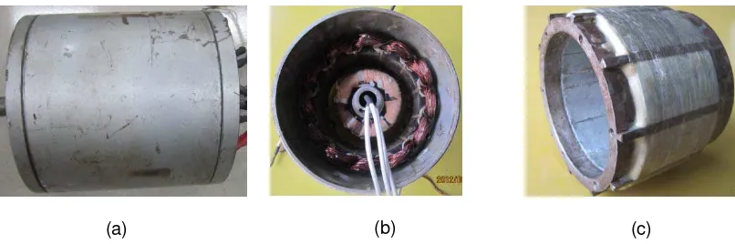
The prototype of the DSBLDC is shown in Figure 8. In order to reduce the motor volume and cut costs, a decelerator is installed to the motor.
(a) (b) (c)
Figure 8. The prototype of the DSBLDC, (a) The whole motor, (b) The inner and outer stators, (c) The middle rotor
(a) (b)
(c) (d)
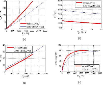
Figure 9. The curves of windings connected in series and the outer windings used alone (98Vdc), (a) Curve of output torque vs. output power, (b) Curve of speed vs. output torque, (c)
Curve of DC bus current vs. output power, (d) Curve of efficiency vs. output power
(a) (b)
(c) (d)
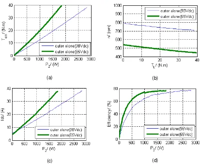
Figure 10. The curves of the outer windings used alone with the voltages of 98Vdc and 65Vdc, (a) Curve of torque vs. output power, (b) Curve of speed vs. output torque, (c) Curve of DC
bus current vs. output power, (d) Curve of efficiency vs. output power
5. Conclusion
This paper focuses on the design and performance analysis of DSBLDC with the supports from the results of FEA and prototype motor experiments. Based on the works above, conclusions can be obtained as follows:
1) According to the series magnetic circuit structure of the DSBLDC, a design method is proposed. The DSBLDC can be divided into an outer-rotor BLDC and an inner-rotor BLDC which can be designed individually, therefore, the conventional BLDC model designed by available magnetic circuit design methods and sofewares can be practically used in DSBLDC design, which will simplify the design process of DSBLDC.
2) DSBLDC can output various running states with different winding connection modes, which will benefit the EV’s starting, accelerating, load climbing, overtaking, etc. by winding switching.
In conclusion, the design method is practical in the DSBLDC design to achieve excellent performance of DSBLDC for EV drive.
References
[1] Niu S, Chau K T, Jiang J Z, Chunhua Liu. Design and Control of a New Double-Stator Cup-Rotor Permanent-Magnet Machine for Wind Power Generation. IEEE Transactions on Magnetics. 2007; 43(6): 2501-2503.
[2] Chai Feng, Zhu Chunbo, Cheng Shukang. Calculation for Electromagnetic Torque of Double-stator Permanent-magnet Synchronous motor. Harbin Institute of Technology. 2000; 7(2): 58-61.