DEVELOPMENT OF PACK BORONIZING FOR AUTOMOTIVE APPLICATION
MUHAMMAD HIZRAN BIN KAMALUDIN
FOR AUTOMOTIVE APPLICATION
MUHAMMAD HIZRAN BIN KAMALUDIN
Thesis submitted in partial fullfillment of requirements for the award of a Bachelor Degree in Mechanical Engineering
(Structure &Materials)
Fakulti Kejuruteraan Mekanikal Universiti Teknikal Malaysia Melaka
i
SUPERVISOR DECLARATION
“I hereby declare that I have read this thesis and in my opinion this thesis is sufficient in terms of scope and quality for the award of the degree of
Bachelor of Mechanical Engineering (Structure & Materials)”
Signature: ...
DECLARATION
“I hereby declare that the work in this thesis is my own except for summaries and quotations which have been duly acknowledged.”
Signature: ...
iii
ACKNOWLEDGEMENT
v
ABSTRACT
ABSTRAK
Penyusukboronon adalah rawatan kimia dan suhu untuk tujuan mengeraskan permukaan logam dimana atom boron bercampur dengan logam asas, memberi tahap kekerasan yang tinggi, ketahanan terhadap kakisan dan meningkatkan jangka hayat kepada 3 - 10 kali lebih dari logam asal. Banyak aplikasi yang menggunankan rawatan permukaan ini secara meluas. Kajian ini adalah bertujuan untuk menbincangkan kesan-kesan penyusukboronan ke atas kekerasan logam sebelum dan selepas penyusukboronan. Jenis logam yang digunakan dalam kajian ini ialah Stainless steel AISI 316 sebagai spesimen. Serbuk penyusukboron yang digunakan adalah Ekabor 1. Pek proses boronizing melibatkan pembenaman logam ke dalam
boronizing campuran serbuk. Spesimen-spesimen yang tidak diaplikasikan proses
vii
TABLE OF CONTENTS
CHAPTER TITLE PAGE
SUPERVISOR DECLARATION i
DECLARATION ii
DEDICATION iii
ACKNOWLEDGEMENT iv
ABSTRACT v
ABSTRAK vi
TABLE OF CONTENT vii
LIST OF TABLES x
LIST OF FIGURES xi
LIST OF SYMBOLS xiii LIST OF ABBREVIATIONS xiv
CHAPTER 1 INTRODUCTION
1.1 Background 1
1.2 Objectives 2
1.3 Scope 3
1.4 Problem Statement 3
CHAPTER 2 LITERATURE REVIEW
2.1 Boronizing 4
2.3 Advantages of Boronizing 11 2.4 Disadvantages of Boronizing 13
2.5 Stainless Steel 13
2.5.1 Types Of Stainless Steel 14 2.5.2 Advantages of Stainless Steel 15
CHAPTER 3 METHODOLOGY
3.1 Process Flow 16
3.2 Materials
3.2.1 Stainless Steel 17
3.2.2 Grade 17
3.2.3 Composition 18
3.3 Selection of Automotive Part 19
3.4 Specimen Preparation 21
3.4.1 Boronizing Powder 22
3.5 Boronizing Procedure 23
3.6 Operating Condition 3.6.1 Temperature and Treatment Time 26 3.7 Vickers Microhardness
3.7.1 Hardness Test Apparatus And Procedures 27 3.8 Microstructure
3.8.1 Step to obtain microstructure 28 3.9 Research Done in this Study
3.9.1 Fabrication Of Container Which Suits The Selected Automotive Parts 31 3.10 Expected Outcome After Boronizing Treatment
3.10.1 Optimum Thickness Of Boride Layer 32
CHAPTER 4 RESULTS AND ANALYSIS
4.1 RESULTS
ix
4.1.2 Hardness Test for Gear 36
4.1.3 Hardness Test for Bearing 37
4.1.4 Gear Microstructure 39
CHAPTER 5 CONCLUSION 44
CHAPTER 6 RECOMMENDATION 45
REFERENCES 46
LIST OF TABLE
NUM. TITLE PAGE
1.1 Typical Part For Boronizing And The Benefit
Of Boronizing 2
2.1 Microhardness Of Different Boride Phases Formed After
Boriding Of Different Substrate Materials 5 2.2 Typical Surface Hardness Of Boronized Steels Compare
With Others Treatment And Hard Materials 6 2.3 The Application Of Boronized Ferrous Materials 10 2.4 The Surface Hardness Of Boronized Steels Compares To
Other Treatments And Hard Materials 12 3.1 Chemical Composition Of Austenitic Grade 18 3.2 Mechanical & Physical Properties 19 3.3 Boronizing Parameter for ball bearing 21
3.4 Boronizing parameter for gear 21
3.5 Boronizing agents 23
3.6 Experimental Condition 25
3.7 Temperature and time 26
4.1 Hardness values for boronized gear (Hv) 36 4.2 Hardness values for boronized bearing 38
4.3 Hardness for unboronized bearing 38
xi
LIST OF FIGURES
NUM. TITLE PAGE
2.1 The Effect Of Percent Alloying Elements On The Boride
Layer Thickness 9
2.2 The Hardness Value For Various Materials Surface
Treatment 11
3.1 Process Flow 16
3.2 Microstructure Of Steel AISI316 19
3.3 Stainless Steel On Automotive Parts 20
3.4 Ball Bearing And Gear Specimens 20
3.5 Scales are used to measure the powder condition 22
3.6 Boronizing powder EKABOR 1 23
3.7 Gear placed inside container 24
3.8 Container heated in the furnace 24
3.9 Schematic diagram for boronizing treatment 25 3.10 The container been removed from the furnace after the process 25
3.11 Vickers Microhardness machine 26
3.12 Vickers hardness test measurement 27 3.13 Intermediate polishing the specimens 28
3.14 Fine polishing the specimens 29
3.15 Gear after fine polishing 29
3.16 Etching solution carpenter 30
3.17 Microscope to obtain microstructure 30 3.18 Schematic Diagram Of Boronizing Container 31
3.19 Boronizing Container used 32
4.1 (a) Vickers Microhardness Machine (b) Vickers Microhardness
4.2 (a)Boronized gear (b) Microhardness test indention on gear 35 4.3 Graph showing Rockwell hardness values of gear
with surrounding 5,10 & 15mm 37
4.4 Hardness of boronized bearings 38
4.5 (a) Microstructure before boronizing process
(b) Microstructure after boronizing process 39
4.6 (a) 5mm powder pack surrounding 40
4.6 (b) 10mm powder pack surrounding 40
4.6 (c) 15mm powder pack surrounding 40
4.7 Boride layer thickness of 15mm powder pack surrounding 41 4.8 Graph showing Boride layer thickness against powder pack
xiii
LIST OF SYMBOLS
NUM. TITLE
LIST OF ABBREVIATIONS
U.T.e.M : Universiti Teknikal Malaysia Melaka
1
CHAPTER 1
INTRODUCTION
1.1 BACKGROUND
Boronizing is a thermochemical process in which boron atoms are diffused into the surface of a workpiece to form complex borides with the base metal. It is a diffusion-controlled process. In addition to nickel, titanium, cobalt alloys and cemented carbides, nearly any ferrous material can be boronized. It should be noted that the diffusion rate slows down in higher-alloyed steels. (R.Davis ,2002)
Boronizing is used successfully for general wear resistance of carbon steel components, combined with the broad range of compatible substrates and the cost-effective nature of the process due to wear/performance benefits provided by the boronized layer. Boronizing is also a good choice for certain tooling applications due to its temperature and wear resistance (R.Davis ,2002). Table 1.1 shows the typical part for boronizing and benefit of boronizing.
Table 1.1 : Typical part for boronizing and the benefit of boronizing (R.Davis ,2002). Typical parts for boronizing Benefits of Boronizing
Moulds for glass bottle production Increased tool and mold life Steam turbine blades, tri-pin blades
and nozzle rings
Good resistance to abrasive, sliding and adhesive wear
Oil & gas field tubing (OCTG) Reduced use of lubrication
Plungers and rollers Can be polished to a high finish
Gears and shafts Reduced tendency to cold weld
Burner nozzles Low coefficient of friction
Pump and valve components
1.2 OBJECTIVE
The objective of this study are :
1. To propose automotive parts which are suitable to be treated by pack boronizing.
2. To design and fabricate a suitable container for powder pack boronizing procedure.
3. To develop pack boronizing process and investigate the hardness of the part using FKM, UTeM facilities.
3
1.3 SCOPE
The scope of this study includes the followings :
1. Experimental works of a proposed boronizing procedure on several automotive parts.
2. Analysis of hardness for the boronized part.
3. Analysis on the influence of the boronizing powder concentration to the hardness of materials.
1.4 PROBLEM STATEMENT
CHAPTER 2
LITERATURE REVIEW
2.1 BORONIZING
Boronizing, or boriding, is a thermochemical treatment that diffuses boron through the surface of metallic substrates. As boron is a component of generally tiny size, it diffuses into a mixture of metals; including ferrous, nickel and cobalt combinations, metal-reinforced carbides and most refractory alloys (Glukhov,1990). The procedure gives the metallic boride layer that the ensuing metallic boride layer yields the extraordinary properties of high hardness, great wear and consumption safety (Suwattananont,2004). The procedure includes warming pre-cleaned material in the temperature range of 700 to 1000 ºC (1300-1832 F) for 1 to 12 hour, in contact with boronaceaus solid (boronizing compound), glue, fluid, or gaseous medium (Sinha,1991).
5
resistance. Nitrided steels, leaded and resulfurised steels are not suitable for boronizing (Sinha,1991).
Material Selection for Boronizing :
Non alloyed and low alloyed steels Stainless steels
cast iron, casted steel
Cold work,hot work, and HSS steel Powder metallurgical steel
Cobalt based materials Cemented carbides Nickel-based alloys
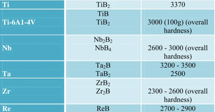
A few trademark peculiarities of borides layers, including morphology, growth, and phase composition which can influence the alloying components in the base material demonstrate in Table 2.1
.
Table 2.1: Microhardness of Different Boride Phases Formed after Boriding of Different Substrate Materials (Sinha,1991).
Substrate
Constituent phases in the boride layer
Microhardness of layer, HV or Kg/mm2
Fe
FeB Fe2B
1900 - 2100 1800 - 2000
Co
CoB Co2B
1850 1500 - 1600
Co-27.5 Cr
CoB Co2B
2200 (100g) ~1550 (100g)
Ni
Ni4B3
Ni2B
Ni3B
1600 1500 900
Inco 100 . . . 1700 (200g)
Mo
Mo2B
Mo2B5
1660 2400 - 2700
W
W2B
WB W2B5
~2700 (overall hardness)
Ti TiB2 3370
Ti-6A1-4V
TiB
TiB2 3000 (100g) (overall
hardness)
Nb
Nb2B2
NbB4 2600 - 3000 (overall
hardness)
Ta
Ta2B
TaB2
3200 - 3500 2500
Zr
ZrB2
Zr2B 2300 - 2600 (overall
hardness)
Re ReB 2700 - 2900
[image:22.595.144.497.71.255.2]Boride layers have various trademark characteristics with unique points of interest over conventional case hardened layers. Boride layers have greatly high hardness values (somewhere around 1450 and 2000 HV) with high liquefying purposes of the constituent stages (Sinha,1991).The common surface hardness estimations of boride steels compared others medicines and other hard materials are recorded shown in Table 2.2. This obviously outlines that the hardness of boride layers produced on carbon steels is much greater than that are delivered by any others conventional surface solidifying treatment.
7
2.1.1 Boronizing of Ferrous Materials
Either a single phase or double-phase of boride layer shaped on iron and steel can be of corresponding to a definite composition from Fe-B, Fe2B acquired for the
single-stage layer, while the double-phase layer comprises of an outside period of FeB and inner part phase of Fe2B with is a saw-tooth structure as the morphology of
the boride layer The saw-tooth structure helps improving the mechanical adherence at the Fe2B /substrate interfaces. (Suwattananont,2004).
The formation of Fe2B stage is expectedly favored than that of FeB stage,
express that FeB stage is more brittle than Fe2B stage. Also, it is observed that FeB
forms a surface under the high tensile stress while Fe2B form a surface under the
high compressive stress. The boronizing process cause to the break arrangement at the FeB which avoids from having the coincidence of Fe2B and FeB stages. Fe2B
interface of double phase layer. The separation of double phase layer under the applied mechanical strain or the thermal/mechanical shock and the crack formation leads to the spalling. After boronizing treatment, annealing process can decrease the occurrence of FeB phase. (Sinha,1991).
Typical properties of the FeB phase are (Sinha,1991): a) Microhardness of about 19-20 GPa.
b) Modulus of elasticity of 590 GPa. c) Density of 6.75 g/cm3
d) Thermal expansion coefficient of 23 x 10-6 /C between 200-600 oC e) Composition with 16 to 16.2 wt% boron.
Lattice parameters: a= 4.053A, b=5.495A, and c=2.946A.
The typical properties of Fe2 B phase are (Sinha,1991) : a) Microhardness of about 18-20 GPa.
b) Modulus of elasticity of 285 to 295GPa. c) Density of 7.43 g/cm3
d) Thermal expansion coefficient of 7.65 x 10⁻⁶ / ºC between 200-600ºC e) Composition with 8.8 wt% boron.
2.1.2 Boronizing Reactions
The boronizing procedure involves two reactions. The first reaction is the beginning stage happens between component boron medium and surface. Boronizing temperature and time and are followed by the growth of boride layer are structured as the function of the cores. Fe2B cores are initially formed and grow as a thin boride
layer at the defect point of the metal surface if there should be an occurrence of ferrous materials. The rich boron product stage on the off chance that the active boron medium is excess for example FeB will form and grow on the Fe2B phase.
(Chatterjee,1989)
The second stage is a diffusion-controlled process, which the thickness of bride layer is formed under an parabolic time law:
x2 = kt [Equation 2.1]
where x as the thickness of the bride layer, t as the boronizing time and k as an constant relying upon the temperature, (Chatterjee,1989). Boron molecules diffuse in the crystallographic direction and form the body-focused tetragonal in the case of ferrous materials grid of Fe2B to accomplish the greatest nuclear thickness along this
direction. The growth of Fe2b is columnar totals of crystals, which shows the
saw-tooth structure. The columnar growth of FeB grow (Sinha,1991) in the crystallographic direction and the saw-tooth structure of FeB is lower than that of Fe2B for the double phase, (Palombarini. and Carbucicchio, 1984)