UNIVERSITI TEKNIKAL MALAYSIA MELAKA
PANIC SENSING AND SPONTANEOUS STABILITY SYSTEM
TO AVOID ACCIDENT
This report is submitted in accordance with the requirement of the University Technical Malaysia Melaka (UTeM) for the Bachelor of Computer Engineering
Technology (Computer System) with Honours
By
CHAU KAR HOO B071210297 921130-08-6073
DECLARATION
I hereby, declared that this report entitled “Panic Sensing And Spontaneous Stability System To Avoid Accident” is the results of my own research except for quotes as
cited in references.
Signature : ……….
Author’s Name : ……….
APPROVAL
This report is submitted to the Faculty of Engineering Technology of University Technical Malaysia Melaka (UTeM) as a partial fulfilment of the requirements for the award of Bachelor of Computer Engineering Technology (Computer Systems) (Hon). The member of the supervisory is as follow:
ii
ABSTRAK
iii
ABSTRACT
iv
DEDICATION
v
ACKNOWLEDGEMENT
First and foremost, I thanks to En Zulhasnizam Bin Hasan for his supervision, encouragement, suggestions and trusted throughout the duration of this project. Without him, I can lost and flee away from the tract I should follow. In addition, I also would like to say thank to other lecturers who are gave me many guidelines and best suggestion to finish this report.
I also would like to express my big thanks to all my colleagues for their support and help to me finish this project. I specially thank to supportive friends for helping me in mechanism and electronics design part.
vi
LIST OF ABBREVIATIONS, SYMBOLS AND NOMENCLATURE ... xi
CHAPTER 1: INTRODUCTION ... 1
1.1 Project background ... 1
1.2 Problem Statement ... 4
1.3 Objective ... 4
1.4 Scope ... 5
1.5 Summary ... 5
CHAPTER 2: LITERATURE REVIEW ... 6
2.1 Introduction ... 6
2.2 Anti-lock Braking System ... 7
2.2.1 Three-channel, three-sensor ABS ... 8
2.2.2 Four-channel, four-sensor ABS ... 9
2.2.3 One-channel, one-sensor ABS ... 9
2.3 Stability Control and Traction Control ... 9
2.4 Velocity of Center of Gravity ... 10
2.4.1 Experimental Estimation of Velocity Central of Gravity ... 11
2.5 Measurement Characteristic ... 15
2.5.1 Data of accelerometer ... 15
vii
2.6 Sideslip... 16
2.6.1 Experimental Estimation of Sideslip ... 17
2.7 Center of Gravity ... 17
2.8 Experimental Results-Plana Model ... 18
CHAPTER 3: METHODOLOGY ... 25
3.1 Introduction ... 25
3.2 Project Implementation ... 26
3.3 Project Flowchart ... 28
3.3.1 Project Flowchart Description ... 29
3.4 Hardware Implementation ... 29
3.4.1 Circuit Design ... 29
3.4.2 Simulation the Circuit Design ... 30
3.4.3 Speed Sensor, Ultrasonic Sensor and Infrared Sensor ... 31
3.4.4 Buzzer and Indicator ... 33
3.4.5 Project Design ... 33
3.4.6 PCB Board Design ... 35
3.4.7 Circuit Implementation ... 36
3.5 Software Implementation ... 37
3.5.1 MPLAB IDE v8.92 Integrated Development Environment ... 37
3.5.2 PIC microcontroller ... 37
3.5.3 Processing Programming ... 38
CHAPTER 4: RESULTS AND DISCUSSION... 39
4.1 Introduction ... 39
4.2 Software Simulation ... 39
4.3 Electrical Design ... 42
viii
4.3.2 Design of Ultrasonic Sensor ... 43
4.3.3 The Circuit Combination ... 43
4.4 Electronic Component ... 44
4.4.1 Arduino UNO ... 44
4.5 Discussion ... 46
4.6 Circuit Implementation ... 48
CHAPTER 5: CONCLUSION AND RECOMMENDATION ... 53
5.1 Introduction ... 53
5.2 Summary ... 53
5.3 Conclusion ... 54
ix
LIST OF FIGURES
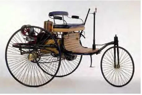
Figure 1.1 Benz patented motor car. ... 1
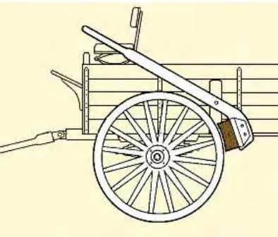
Figure 1.2: The wooden block and lever ... 2
Figure 1.3: Illustration of Hydraulic Brake System ... 2
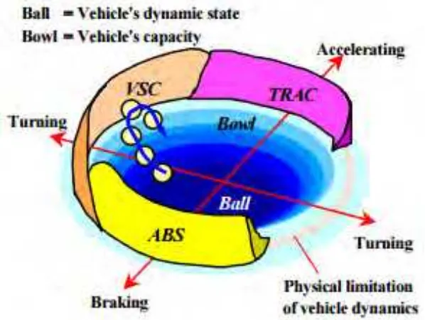
Figure 2.1: Concept of Vehicle Stability Control ... 6
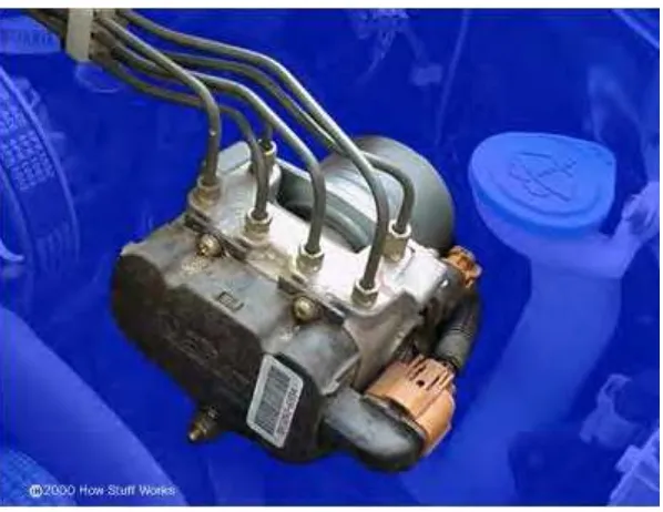
Figure 2.2: Anti-lock brake pump and valves ... 8
Figure 2.3: Estimation block diagram ... 12
Figure 2.4: Estimation of velocity of Center of Gravity & error comparison ... 13
Figure 2.5: System Diagram ... 14
Figure 2.6: Illustration of vehicle sideslip... 16
Figure 2.7: Center of Gravity ... 18
Figure 2.8: Estimation of Heading Angle ... 19
Figure 2.9: Yaw rate and Sideslip Angle Estimation ... 19
Figure 2.10: Roll Center Model with Grade and Superelevation... 20
Figure 2.11: The functional diagram of the vehicle stability control system ... 22
Figure 2.12: Vehicle model ... 23
Figure 2.13: Histogram error estimate for the linear steering with observer states and continued profitability RMS ... 24
Figure 3.1: Flowchart Program ... 28
Figure 3.2: Draft Circuit ... 30
Figure 3.3 Speed sensor ... 31
Figure 3.4 Ultrasonic sensor ... 32
Figure 3.5 Infrared sensor ... 32
Figure 3.6 Light emitting diode (LED) and Buzzer ... 33
Figure 3.7 Location of speed sensor ... 34
Figure 3.8 PCB Layout ... 35
Figure 3.9 PCB Board ... 36
x
Figure 4.1 The program code of measuring the wheel speed. ... 40
Figure 4.2 The program code of analyzing center of gravity ... 41
Figure 4.3 The program code of blind spot detection ... 41
Figure 4.4 Circuit diagram of Infrared Sensor Module... 42
Figure 4.5 Circuit diagram of Transmitter and Receiver of Ultrasonic Sensor Module43 Figure 4.6 Circuit diagram of project ... 44
Figure 4.7 Characteristic of Arduino UNO ... 45
Figure 4.8 Arduino UNO ... 45
Figure 4.9 Top view of the RC with VSAS installed. ... 49
Figure 4.10 Left and Right obstacle detection sensors ... 50
Figure 4.11 The sensor to detect the speed. ... 51
xi
LIST OF ABBREVIATIONS, SYMBOLS AND
NOMENCLATURE
VSA - Vehicle Stability Assist ESP - Electric Stability Program
BMW - Bavarian Motor Works
DSC - Dynamic Stability Control VSAS - Vehicle Stability Assist System ABS - Anti-lock Braking System
TRAC - Traction
GPS - Global Positioning System
RISS - Reduced Inertial Sensor System MEMS - Micro-Electro-Mechanical System
INS - Inertial Navigation System
IMU - Inertial Measurement Unit
KF - Kalman Filter
4WD - 4 Wheel Drive
xii
L1 - front axle distance from center of gravity (m)
L2 - rear axle distance from center of gravity (m)
Fy1 - front lateral tire forces in the car body axis (N)
Fx1 - front lateral tire forces in the car body axis (N)
Fyw1 - front lateral tire forces (N)
Fyw2 - rear lateral tire forces (N)
Vg - velocity of the center of gravity (m/s)
σ
- Front Steering Angle (rad)�
- Sideslip Angle (rad)�
- Tire-Road Friction Coefficientm - Metre
Hz - Hertz
cm - Centimetre
°
- Degreeux,sensor - Longitudinal Velocity at Sensor Location
ax,m, ax,bias - Longitudinal Accelerometer Measurement and Bias
uy,sensor - Lateral Velocity at Sensor Location
1
CHAPTER 1
INTRODUCTION
1.1 Project background
In 1885-1886 year, Carl Benz was developed the first gasoline stationary and the Figure 1.1 is shown the outlook of first invented motor car.
Figure 1.1 Benz patented motor car.
2
Figure 1.2: The wooden block and lever
Many types of advanced brake had been created in 20th century. As the developing in automotive and trucking industries, brake systems improved. Early automobiles had band brake which were then followed by drum brakes, both were applied mechanically through linkage. In the 1920’s – 1940’s, hydraulic systems were a major improvement and the hydraulic system is work when the force is applied at one point is transmitted to another point using fluid that unable being compress. The Figure 1.3 illustrated the simple structure of hydraulic brake system.
3
Since the 1960’s, disc brakes have become familiar and not strange on cars and trucks. Disc brake almost similar the brakes on a bicycle. Bicycle brakes consist of caliper, which squeezes the brake pads against the wheel. The brake pads squeeze the rotor instead of the wheel, instead of through a cable, the force is transmitted hydraulically in the disc brakes. The pads and disc will generate friction and slows down the disc.
4
hydroplaning that causes sudden loss and unexpected traction at the rear wheels. Due to the fast response time of the system's stability control, this traction losing can be count on, and throttle reduced before traction is overwhelmed, helping to prevent rotation and keeping full control of the vehicle. Undoubtedly, stability control could guide to an increase safe for regular driver in normal driving situation.
1.2 Problem Statement
Nowadays, drivers do not realize the vehicle stability and condition and causing minor or severe accident. Driver themselves do not aware when will be the situation and how serious it could be, they just depends on the so call vehicle stability system. Drivers do not able to analyze the vehicle stability when they are driving, they do not know how fast the speed they can drive. According to the Statistic of Road Accident in Malaysia, the road traffic accident rate from 1980 until 2000 have been increased dramatically. In 2004 to 2013, the death of people in road accidents is up to 65,850 people. In other words, the driver should be alert before the unexpected situation is happened and sufficient time to slow down or control the vehicle to avoid accident.
1.3 Objective
1. To develop a Vehicle Stability Assist System (VSAS). 2. To analyze the vehicle stability.
3. To analyze the wheel speed and the central of gravity of the vehicle. 4. To ensure the vehicle is under control by driver.
5
1.4 Scope
This project is to develop a Vehicle Stability Assist System (VSAS). VSAS is able to analyze the stability of the vehicle by calculating the wheel speed and central of gravity. The relationship between vehicle speed and central of gravity will be measured to maintain the vehicle stability and alert the driver before unexpected condition happened.
1.5 Summary
6
CHAPTER 2
LITERATURE REVIEW
2.1 Introduction
Nowadays vehicle stability control system is brand new concept and idea to reinforce and enhance the stability problem of vehicle and also countering certain emergency situation. However, there are few aspects that will cause the vehicle being unstable, that are centre of gravity of the vehicle, vehicle speed, sideslip angle, road friction and the braking force at individual wheel. Majority of vehicle user doesn’t really understand the concept and function of vehicle stability control. To explain the concept of vehicle stability control, an analogy will be used referring to Figure 2.1.
7
In above Figure 2.1, vehicle dynamic state is represented by the ball and the capacity of vehicle is the bowl. Control losing can be represents as the ball went over the rim of the bowl. Under normal driving phenomenon, the bowl can be said as enough large and deep for the motion of the ball. When the ball motion becomes over limit, However, as when steering the vehicle suddenly changed, or a smaller bowl into such as when driving on icy roads or snow, it's likely to be repeated over the rim of the bowl. This can be explained why the vehicle becomes hard to handle. Some survey has been done on the relationship between the vehicle stability control and the factors to activate the system as well as the make the vehicle to be more stable.
2.2 Anti-lock Braking System
8
Figure 2.2: Anti-lock brake pump and valves
2.2.1 Three-channel, three-sensor ABS
9
2.2.2 Four-channel, four-sensor ABS
This is the best scheme. There are speed sensors on all four wheels and a separate valve for all four wheels. With this setup, the controller monitors each wheel individually to ensure they achieve maximum braking power.
2.2.3 One-channel, one-sensor ABS
These systems typically found on pickup trucks with rear-wheel ABS. It has a valve which controls both rear wheels, and a speed sensor, which is located on the rear axle. The system operates in conjunction with the rear end of a three channel system. The rear wheels are monitored together and both have started to lock up before the ABS kicks. In this system, it is also possible that one of the rear wheels will lock, reducing brake effectiveness. The system is easy to identify. Usually there will be a brake line going through a T-fitting to both rear wheels. You can search by looking for speed sensor electrical connection near the rear axle differential housing.
2.3 Stability Control and Traction Control