Review Article
A Review of Active Yaw Control System for Vehicle Handling
and Stability Enhancement
M. K. Aripin,
1Yahaya Md Sam,
2Kumeresan A. Danapalasingam,
2Kemao Peng,
3N. Hamzah,
4and M. F. Ismail
51Control, Instrumentation & Automation Department, Faculty of Electrical Engineering, Universiti Teknikal Malaysia Melaka, 76100 Durian Tunggal, Melaka, Malaysia
2Department of Control & Mechatronics, Faculty of Electrical Engineering, Universiti Teknologi Malaysia, 81310 UTM Johor Bahru, Johor, Malaysia
3Temasek Laboratories, National University of Singapore 5A Engineering Drive 1, Singapore 117411 4Faculty of Electrical Engineering, UiTM Pulau Pinang, 13500 Permatang Pauh, Pulau Pinang, Malaysia
5Industrial Automation Section, Universiti Kuala Lumpur Malaysia France Institute, Section 14, Jalan Teras Jernang, 43650 Bandar Baru Bangi, Selangor, Malaysia
Correspondence should be addressed to M. K. Aripin; [email protected]
Received 23 January 2014; Revised 8 May 2014; Accepted 15 May 2014; Published 12 June 2014
Academic Editor: Aboelmagd Noureldin
Copyright © 2014 M. K. Aripin et al. his is an open access article distributed under the Creative Commons Attribution License, which permits unrestricted use, distribution, and reproduction in any medium, provided the original work is properly cited.
Yaw stability control system plays a signiicant role in vehicle lateral dynamics in order to improve the vehicle handling and stability performances. However, not many researches have been focused on the transient performances improvement of vehicle yaw rate and sideslip tracking control. his paper reviews the vital elements for control system design of an active yaw stability control system; the vehicle dynamic models, control objectives, active chassis control, and control strategies with the focus on identifying suitable criteria for improved transient performances. Each element is discussed and compared in terms of their underlying theory, strengths, weaknesses, and applicability. Based on this, we conclude that the sliding mode control with nonlinear sliding surface based on composite nonlinear feedback is a potential control strategy for improving the transient performances of yaw rate and sideslip tracking control.
1. Introduction
In vehicle dynamic control of road-vehicle, controlling the lateral dynamic motion is very important where it will determine the stability of the vehicle. One of the prominent approaches that are reported in the literature for lateral dynamics control is a yaw stability control system. In order to design an efective control system, it is essential to determine an appropriate element of yaw stability control system. In this paper, the elements of yaw stability control system, that is, vehicle dynamic models, control objectives, active chassis control, and its control strategies as depicted inFigure 1, are extensively reviewed.
he linear and nonlinear vehicle models that described the behaviour of lateral dynamic are explained for controller
design and evaluation purpose. To achieve the control objec-tives, it is essential to control the variables of yaw rate and sideslip angle in order to ensure the vehicle stable. It is required that the actual yaw rate and sideslip angle have fast responses and good tracking capability in following the desired responses. During critical driving condition or manoeuvre, inappropriate commands by the driver to control the steering and braking can cause the vehicle to become unstable and lead to an accident. herefore, an active control for yaw stability control system is essential to assist the driver to keep the vehicle stable on the desired path. By implementing an active chassis control of steering or braking or integration of both systems, the active yaw control system can be realized.
2 International Journal of Vehicular Technology
Vehicle dynamics control
Vertical dynamics control Longitudinal dynamics control Lateral dynamics control
Lane warning detection system Lane keeping system
Yaw stability control system
Vehicle dynamics models Control objectives Active chassis control Control strategies
Figure 1: Yaw stability control system for vehicle lateral dynamic.
Vehicle dynamic models
Linearized model Nonlinear model
8 DOF
7 DOF 14 DOF 2 DOF
Figure 2: Vehicle dynamic models.
In real driving condition, the lateral dynamics of vehicle are incorporated with uncertainties such as diferent road surface condition, varying vehicle parameters, and crosswind disturbance. In yaw stability control system, these pertur-bations could inluence the yaw rate and sideslip tracking control performances. From the control system point of view, the transient performances of tracking control are essential. However, from the reviewed control strategies in the literature, the controllers are not designed to cater this matter. herefore, an appropriate robust control strategy should be proposed to improve the transient performances of the yaw rate and sideslip tracking control in the presence of uncertainties and disturbances. As a inding from the reviews, this paper briely discussed a possible high performance robust tracking control strategy that can be implemented for yaw stability control system.
he review begins with vehicle dynamics models in
Section 2. he yaw stability control objectives are discussed in Section 3 and followed by active chassis control for in
Section 4. Yaw stability control strategies and problems are reviewed in Sections5and6, respectively. InSection 7, a high performance robust tracking controller using sliding mode control and composite nonlinear feedback is discussed. he controller evaluation is discussed inSection 8and ended with conclusion inSection 9.
2. Vehicle Dynamics Models
In order to examine, analyse, and design the controller for yaw stability control system, vehicle dynamics models are essential where the mathematical modelling of vehicle dynamic motion is obtained based on Newton’s 2nd law that describes the forces and moments acting on the vehicle body and tires. In general, there are two categories of vehicle dynamic model, that is, nonlinear vehicle model and lin-earized vehicle model as depicted inFigure 2. he following subsections will discuss the nonlinear vehicle model for simulation and linearized vehicle model for controller design purpose.
2.1. Vehicle Model for Simulation. he nonlinear vehicle
model is regularly used to represent and simulate the actual vehicle for controller evaluation and validation. In recent years, researches in [1–5] have utilized nonlinear vehicle model for vehicle handling and stability improvement stud-ies. Figure 3 shows the typical nonlinear vehicle model in cornering manoeuvre.
Fx1�f �f
Fy1
d Fx2
Fy2
x
�
y r Mz
lf
lr
Fx3
Fy3
Fy4
Fx4
d
Figure 3: Nonlinear vehicle model [6].
gravity (CG) �� and ��, respectively. he vehicle forward velocity of centre of gravity (CG) is V, lateral velocity is V�, and longitudinal velocity isV�. Other important vehicle
parameters are vehicle mass �, moment of inertia��, and front/rear tire cornering stifness ��/��. he wheels are numbered as subscript number with(1)for front-let,(2)for front-right,(3)for rear-let, and(4)for rear-right.
Longitudinal tire force,���, depends directly on tire slip ratio, �� while lateral tire force, ���, depends directly on tire sideslip angle,��. For smaller slip angle and slip ratio, lateral tire force is described as a linear function of the tire cornering stifness and tire sideslip angle while longitudinal tire force is described as a linear function of the braking stifness and the tire slip ratio. For larger slip angle and slip ratio, longitudinal and lateral tire forces exhibit a nonlinear characteristics. Vehicle dynamic motion with nonlinear tire forces represents a nonlinear system. he nonlinear lateral and longitudinal tire forces can be described using prominent Pacejka tire model as implemented in [1,4,7] or Dugof tire model as utilized in [8–10], while studies in [11] used both tire models.
he nonlinear vehicle model could have diferent number of degree-of-freedom (DOF) where it represents the dynam-ics motions and complexity of vehicle models. As utilized in [2,12–14], the 7 DOF vehicle model represents the dynamic motions of vehicle body, that is, longitudinal, lateral, yaw, and four wheels. he dynamic equations for the longitudinal, lateral, and yaw motions of the vehicle body are described as follows.
Longitudinal Motion.One has the following:
���= � ( ̇V�− �V�)
= (��1+ ��2)cos��+ ��3+ ��4− (��1+ ��2)sin��.
(1)
Lateral Motion.One has the following
��� = � ( ̇V�+ �V�)
= (��1+ ��2)sin��+ (��1+ ��2)cos��+ ��3+ ��4.
(2)
Yaw Motion.One has the following:
�� ̇� = ��(��1cos��+ ��2cos��+ ��1sin��+ ��2sin��)
− ��(��3+ ��4) + ��,
(3)
where��is yaw moment that must be taken into account, that is;�� > 0if the tires tends to turn at�-axis. In (2), the lateral acceleration�� can be expressed in terms of vehicle forward speedV, yaw rate�, and sideslip�as follows:
��= ̇V�+ �V�=V(� + ̇�) . (4)
herefore, the output variable of sideslip�of two-track model can be obtained as follows:
̇� = 1�
V[cos� (cos��(��1+ ��2) −sin��(��1+ ��2))
−sin� (sin��(��1+ ��2) −sin��(��1+ ��2))] − �.
(5)
while the output variable of yaw rate� can be determined from (3) and obtained as follows:
̇� = 1��[��(��1cos��+ ��2cos��+ ��1sin��+ ��2sin��)
−��(��3+ ��4) + ��] .
(6)
In vehicle dynamic studies, each wheel represents 1 DOF. hus, there are 4 DOF for road-vehicle with 4 wheels. he dynamic motion for each wheel is described as follows:
��� ̇��= −������+ ���− ���, (7)
where ̇�is wheel angular acceleration,�,��is wheel radius, ��is wheel inertia,��� is braking torque, and���is driving
torque.
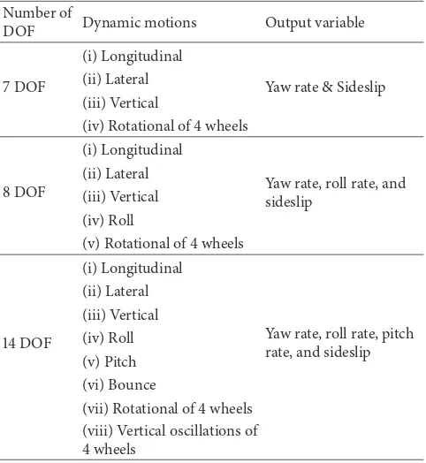
Another nonlinear vehicle model used in the previous research is 8 DOF vehicle model that is extensively used in [4, 5, 9–11, 15–18]. For more accurate simulation and validation, the 14 DOF vehicle model is used in [1,19,20]. he comparison between the number of DOF of nonlinear vehicle models that have been discussed above can be summarized and compared inTable 1.
4 International Journal of Vehicular Technology
Table 1: Number DOF of nonlinear vehicle models.
Number of
DOF Dynamic motions Output variable
7 DOF
(i) Longitudinal
Yaw rate & Sideslip (ii) Lateral
(iii) Vertical
(iv) Rotational of 4 wheels
8 DOF
(i) Longitudinal
Yaw rate, roll rate, and sideslip
(ii) Lateral (iii) Vertical (iv) Roll
(v) Rotational of 4 wheels
14 DOF
(i) Longitudinal
Yaw rate, roll rate, pitch rate, and sideslip
(vii) Rotational of 4 wheels (viii) Vertical oscillations of 4 wheels
implemented in [21–26]. By using this sotware based vehicle model, the dynamic behaviour of vehicle is more precise similar to a real vehicle. However, for yaw rate and sideslip tracking control in yaw stability control system, the 7 DOF nonlinear vehicle model as discussed in the above equations and shown inTable 1is adequate for simulation and evalua-tion of the design controller.
2.2. Vehicle Model for Controller Design. In vehicle dynamic
studies, the classical bicycle model as shown in Figure 4
is prominently used for yaw stability control analysis and controller design as utilized in [1, 3, 8, 26–30]. his model is linearized from the nonlinear vehicle model based on the following assumptions.
(i) Tires forces operate in the linear region.
(ii) he vehicle moves on plane surface/lat road (planar motion).
(iii) Let and right wheels at the front and rear axle are lumped in single wheel at the centre line of the vehicle. (iv) Constant vehicle speed i.e. the longitudinal
accelera-tion equal to zero (��=0)
(v) Steering angle and sideslip angle are assumed small (≈0).
(vi) No braking is applied at all wheels.
(vii) Centre of gravity (CG) is not shited as vehicle mass is changing.
(viii) 2 front wheels have the same steering angle.
(ix) Desired vehicle sideslip is assumed to be zero in steady state.
Figure 4: Bicycle model [31].
In the simplest form of planar motion, this model consists of 2 DOF for lateral and yaw motions as describe in the following equations.
Lateral Motion.One has the following:
�V( ̇� + �) = (���+ ���) − �. (8)
Yaw Motion.One has the following:
�� ̇� = ��⋅ ���− ��⋅ ���. (9)
In this model, the front and rear lateral tire forces���and���, respectively, exhibit linear characteristics and described as a linear function of the front and rear cornering stifness,�� and��, as follows:
���= ����,
���= ����,
(10)
where the front and rear tire sideslip angle, ��, and�� for linear tire forces are given in the following equations:
��= ��− � −��V�,
�� = − � + ��V�.
(11)
By rearranging and simplifying (8)–(11), the diferential equations of sideslip and yaw rate variables can be simpliied as a linear state space model as follows:
Control objectives
Yaw rate Side slip Yaw rate and side slip
Figure 5: Yaw stability control objectives.
mass,�� is moment of inertia,�� and �� are distance from front and rear axle to centre of gravity, respectively, V is
vehicle speed, and front tire steer angle �� is the input � to the model. Notice that vehicle speedVis assumed always
constant which means the vehicle is not involved with accel-erating and braking. Hence, only lateral and yaw motions are analysed.
Besides that, the bicycle model is also regularly used as desired or reference model to generate the desired response of the yaw rate and sideslip angle based on steady state condition or approximated irst order response. In designing the control strategy based on vehicle active chassis control, the linear state space model in (13) is essential.
3. Yaw Stability Control Objectives
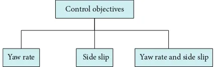
A vehicle yaw rate � and sideslip angle � are signiicant variables in vehicle yaw stability control system. As stated in [32], control objectives of yaw stability control system may be classiied into three categories, that is, yaw rate control, sideslip control, and combination of yaw rate and sideslip control as illustrated inFigure 5.
One of the control objectives of yaw stability control system is yaw rate,r. An ability to control the actual yaw rate close to desired response will improve the handling or manoeuvrability of the vehicle. he desired yaw rate which is generated by reference model should be tracked by the controller in order to improve the handling performance as mentioned in [2,4,13,15,18,27,33,34]. In the steady state condition, the desired yaw rate response��can be obtained by using the following equation:
��=
V
(��+ ��) + ���V2 ⋅ ��, (13)
where stability factor���is depending on the vehicle param-eters and deined as follows:
���=� (����− ����)
(��+ ��) ���� .
(14)
Another control objective is the vehicle sideslip angle, �, that is, the deviation angle between the vehicle longitudinal axis and longitudinal axis and its motion direction. he control of sideslip angle close to steady state condition means controlling the lateral stability of the vehicle. For the steady state condition, the desired sideslip is always zero, that is, �� = 0as mentioned in [1,6,9,11,17,26,35]. herefore, to
improve the vehicle handling and stability performances, it
is essential to control both yaw rate and sideslip responses. In order to achieve these control objectives, the proposed controller must be able to perform the control task of the yaw rate and sideslip tracking control.
4. Active Chassis Control
Steering and braking subsystems or actuator are part of the vehicle chassis. he active control of yaw stability control system can be realized through active chassis control, that is, direct yaw moment control or active steering control or integrated actives steering and direct yaw moment control as shown inFigure 6. In direct yaw moment control which can be implemented by active braking or active diferential torque distribution, the required yaw moment is generated by the designed controller that controls the desired yaw rate and sideslip. In active steering control, the wheel steer angle that commanded by the driver is modiied by adding corrective steer angle from the designed controller. his control strategy can be implemented either using active front steering (AFS) or active rear steering (ARS) or four-wheel active steering (4WAS) control. In order to control two variables of the yaw rate and sideslip efectively, two diferent control mechanisms are required. hus, related research works on the integration of two vehicle chassis control, that is, integrated active steer-ing and direct yaw moment control, have been extensively conducted recently. he review of direct yaw moment control, active steering control, and integrated active steering and direct yaw moment control are discussed in the following subsections.
4.1. Direct Yaw Moment Control. Direct yaw moment control
is one of the prominent methods for yaw stability control where extensive research works using this method have been conducted with diferent control strategies and algorithms as reported in [1,3,5,8,9,15–18,25,26,30,36]. It is recognized as an efective method to enhance the vehicle lateral stability during critical driving manoeuvre by controlling the slip ratio of individual wheel. As illustrated inFigure 7, the required corrective yaw moment, Δ�� which is generated by the transverse distribution of braking forces between the vehicle wheels is calculated by the designed controller based on the error between actual and desired vehicle model that have been discussed inSection 2. Another approach of direct yaw moment control is active distribution torque. By using an active diferential device as established in [19, 20, 37, 38], the let-right driving torque is distributed by this device to generate the required corrective yaw moment,Δ��.
As mentioned inSection 2, direct yaw moment control design is based on the linear state space model. As described in (15),��is considered as control input and front steer angle ���is assumed as disturbance:
[ ̇�] = [̇� �11 �12
�21 �22] [��] + [
�1
�2] ���+ [� 3
6 International Journal of Vehicular Technology
Direct yaw moment control Active steering control Integrated active steering and direct
yaw moment control Active chassis control
Active braking
Active
differential AFS ARS 4WAS
Figure 6: Active chassis control.
�fd
Figure 7: Direct yaw moment control [15].
[ ̇�] =̇� [[[[
Although direct yaw moment control could enhance the vehicle stability for critical driving conditions, it may be less efective for emergency braking on split road surface. At high vehicle speed steady state cornering, direct yaw moment control could decrease the yaw rate and increase a burden to the driver. To overcome this disadvantage, active steering control is proposed.
4.2. Active Steering Control. Active steering control is another
approach to improving the vehicle yaw stability, especially for steady state driving condition where the lateral tire force is operated in the linear region. Research works of active steering control have been continuously conducted in order to improve the handling and stability performances as reported in [7,13,39–42]. In general, active steering control can be divided into three categories, that is, active front steering (AFS) control, active rear steering (ARS) control, and four-wheel active steering (4WAS) control, as shown in
Figure 6. As road-vehicle normally has front-wheel steering, AFS control becomes favourite approach among researchers as it can be combined with active braking and/or suspension control. In the AFS control diagram, as shown inFigure 8, the
front wheel steers angle is a sum of steer angle commanded by the driver���and a corrective steer angle��generated by the controller. his corrective steer angle is computed based on yaw rate and sideslip tracking errors�1and�2as implemented in [6,43–47].
For control design and analysis of AFS control, the linear state state space model as described in (16) is used. Noted that this equation is similar to equation (12) but the front wheel steer angle,��= ���+ ��:
On the other hand, ARS control is used to improve the vehicle response for low speed cornering manoeuvres with the input to the control system being the rear steering angle ��. In order to enhance the manoeuvrability at low speed
Controller
Figure 8: Active front steering control [45].
Controller Desired
vehicle model Actual vehicle model
�fd
Figure 9: Integrated active front steering-direct yaw moment control [53].
4.3. Integrated Active Chassis Control. he integrated active
chassis control has become a popular research topic in vehicle dynamics control as discussed in [50]. Vehicle dynamics control can be greatly achieved by integrating the active chassis control of active steering, active braking, and active suspension or active stabiliser as implemented in [12,23,51,
52]. Since road-vehicle is usually equipped with front-wheel steering and braking system, an integration and coordination of active front steering and direct yaw moment control are the favourite approaches to achieving the objectives of yaw rate and sideslip control as reported in [2,10,11,27,28,53–
59]. In this approach, the corrective front wheel steers angle �� and corrective yaw moment�� are considered as two
independent control inputs to the vehicle as illustrated in
Figure 9.
For controller analysis and design of integrated active front steering-direct yaw moment control, the linear state space model used is describe as follows:
[ ̇�] =̇� [[[[
he principle of active chassis control of steering and braking for yaw stability control has been discussed. From the above discussion, the diferences, advantages, and disad-vantages of each active chassis control can be digested as tabulated in Table 2. From this table, it can be observed
that, by implementing integrated active front steering-direct yaw moment control, the lateral and yaw motions can be controlled simultaneously using two independent control inputs from two diferent actuators, that is, steering and braking. hus, this approach could enhance the vehicle yaw stability where the yaw rate and sideslip can be controlled efectively in emergency manoeuvres and the steady state driving condition.
As a conclusion, active chassis control is essential for active yaw stability control system. herefore, to achieve the yaw stability control objectives, the control strategies for yaw rate and sideslip tracking control are developed based on this active chassis control. he following section will review and discuss the control strategies and algorithms that have been developed in the past.
5. Yaw Stability Control Strategies
8
In
ter
na
tio
n
al
Jo
ur
na
lo
f
V
ehic
u
la
r
T
echnolog
y
Table 2: Types of active chassis control.
Vehicle actuator Active chassis control Advantages Disadvantages
Brakes Direct yaw moment control(DYC) Active brakingactive diferential (i) Efective for critical driving condition(ii) Good for sideslip/wheelslip control
(i) Less efective for braking on split road surface
(ii) Decrease yaw rate during steady state driving condition (iii) Active diferential need extra devices
Steering Active steering control
(ASC)
Active front steering (AFS) control
(i) Efective for steady state driving condition (ii) Ease to integrate with braking control (iii) Good for yaw rate control
Less efective during critical driving condition
Active rear steering (ARS) control
(i) Rear wheel steer angle can be controlled
(ii) Good for yaw rate control Less efective during critical driving condition
4 wheels active steering (4WAS) control
(i) Two diferent steer inputs
(ii) Goof for yaw rate control Less efective during critical driving condition
Steering and brake Integrated AFS-DYC control
(i) Two diferent inputs from two diferent actuator (steering and braking)
(ii) Good for yaw rate and sideslip control
for yaw stability control and the controllers performances are compared and evaluated.
he control strategies are designed based on active chassis control as discussed inSection 4. In active braking or active diferential which operates based on direct yaw moment control (DYC), various robust control strategies have been designed. As reported in [3], yaw stability control that consists of tire force observer and cascade controller that is based on sliding mode and backstepping control method is designed. To solve the external disturbance as discussed in [16], the robustness of mixed-sensitivity yaw stability con-troller is guaranteed for external crosswind and emergency manoeuvres. To cater the uncertainty from longitudinal tire force, the controller for wheel slip control is designed using SMC algorithm for vehicle stability enhancement [17]. As discussed in [20], the second order sliding mode (SOSM) and enhanced internal mode control (IMC) are designed as feedback controller to ensure the robustness against uncertainties and control saturation issues. Both controllers’ performances are compared and analysed for yaw control improvement based on rear active diferential device. Besides that, the sliding mode control algorithm is also utilized to determine the required yaw moment in order to minimize the yaw rate error and side-slip angle for vehicle stability improvement [22]. To overcome the uncertainties parameters and guarantee robust yaw stability in [25], the control strategy that consists of disturbance observer to estimate feedforward yaw moment and optimal gain-scheduled�∞ is designed. In the study of [30], the robust yaw moment controller and velocity-dependent state feedback controller are matrixed by solving inite numbers linear matric inequality (LMI). By using this approach, the designed controller is able to improve the vehicle handling and lateral stability in the presence of uncertainty parameters such as vehicle mass, moment of inertia, cornering stifness, and variation of road surfaces and also control saturation due to the physical limits of actuator and tire forces.
In active steering control, robust control strategies are designed to overcome the uncertainties and external dis-turbance problems. In [7], adaptive sliding mode control is utilized to estimate the upper bounds of time-derived hyperplane and uncertainties of lateral forces. As discussed in [13], feedback �∞ control is implemented for robust stabilization of yaw motion where speed and road adhesion variations are considered as uncertainties and disturbance input. As reported in [49], a proportional active front steering control and proportional-integral active rear steering control are designed for four-wheel steering (4WS) vehicle with the objective to overcome the uncertainties of vehicle mass, moment of inertia, and front and rear cornering stifness coeicients. To ensure a robust stability against system uncer-tainties, the automatic path-tracking controller of 4WS vehi-cle based on sliding mode control algorithm is designed [24]. In this study, the cornering stifness, path radius luctuation, and crosswind disturbance are considered as uncertainty parameters and external disturbance. As reported in [42], the model reference adaptive nonlinear controllers is proposed for active steering systems to solve the uncertainties and nonlinearities of tire’s lateral forces. Quantitative feedback
theory (QFT) technique is implemented for robust active front steering control in order to compensate for the yaw rate response in presence of uncertainties parameters and reject the disturbances [45]. As discussed in [48], robust controller for 4WS vehicle is also designed based on�-synthesis control algorithm which considers the varying parameters induced by the vehicle during driving conditions as uncertainties while the study in [60] designed the steering control of vision based autonomous vehicle based on the nested PID control to ensure the robustness of the steering controller against the speed variations and uncertainties of vehicle parameters.
In integrated active chassis control, an appropriate control scheme is designed to meet the control objectives. Studies in [2,27,33] have designed the control scheme that consists of reference model based on linear parameter-varying (LPV) formulation and static-state feedback controller with the objective to ensure the robust performance for integrated active front steering and active diferential braking control. In these studies, tire slip angle, longitudinal slips, and vehicle forward speeds are represented as uncertainty parameters. As reported in [4], integrated robust model matching chassis controller that integrates active rear wheel steering control, longitudinal force compensation, and active yaw moment control is designed using �∞ controller based on linear matrix inequalities (LMIs) for vehicle handling and lane keeping performance improvement. In integrated active front steering-direct yaw moment control, an optimal guaranteed cost control (OGCC) technique is utilized in [10]. In this study, tire cornering stifness is treated as uncertainty during variation of driving conditions. As discussed in [11], an adaptive integrated control algorithm based on direct Lya-punov method is designed for integrated active front steering and direct yaw moment control with cornering stifness is considered as a variation parameter to ensure the robustness of designed controller. As reported in [23], sliding mode controller is utilized for stabilising the forces and moments in integrated control schemes that coordinated the steering, braking, and stabiliser. In this study, the integrated control structure is composed of a main loop controller and servo loop controller that computes and distributes the stabilizing forces/moments, respectively.
From the above discussion, these control strategies and algorithms can be summarized and compared in terms of their active chassis control, control objective, advantages, and disadvantages as tabulated in Table 3. In conclusion, an appropriate control strategy must be designed based on particular algorithm. Robust control algorithms such as �∞, SMC, IMC, OGCC, QFT. are essential to solve the
uncertainties and disturbance problems that inluenced the yaw stability control performances. It is revealed that the designed controllers in the above discussion are able to track the desired yaw rate and vehicle sideslip response considering external disturbances and system uncertainty.
6. Yaw Stability Control Problems
10
In
te
rn
at
io
n
al
Jo
u
rn
al
o
f
V
eh
icula
r
T
ec
h
n
o
lo
g
y
Table 3: Yaw stability control algorithms.
Control algorithms Active chassis control Control objective Advantages Disadvantages
PID controller DYC sideslip Anti-wind-up strategy to avoid high
overshoot and large settling time Uncertainties are not consider
LMI static state feedback Integrated AFS-active diferential Yaw rate and sideslip robust for uncertainties
Transient response
improvement is not consider
Transient response
improvement is not consider
�∞ Integrated chassis control, active steering Yaw rate Robust for uncertainties, reject disturbance
SMC DYC, active steering Yaw rate and sideslip robust for uncertainties and rejectdisturbance
OGCC Integrated AFS-DYC Yaw rate and sideslip Robust for uncertainties
Adaptive integrated control Integrated AFS-DYC Yaw rate and sideslip Robust for uncertainties
Mixed-sensitivity minimization
control DYC Yaw rate Robust for uncertainty, reject disturbance
PI controller 4WAS Yaw rate Robust for uncertainties
IMC DYC Yaw rate Robust for uncertainty
QFT AFS Yaw rate Robust for uncertainties, reject disturbance
�synthesis control 4WAS Yaw rate and sideslip Robust for uncertainties
SMC-backstepping Yaw rate and sideslip Robust for nonlinearities Uncertainties are not
considered
SMC-FLC Integrated steering, brake, and
suspension
Yaw rate, sideslip, and roll
angle Robust for uncertainties and nonlinearities Transient response
improvement is not consider
system where the tire dynamic exhibit nonlinear character-istics, especially during critical driving conditions such as a severe cornering manoeuvre. he main problems of yaw rate and sideslip tracking control are uncertainties caused from variations of dynamics parameters as discussed in the previous section such as road surface adhesion coeicients [8, 13, 33, 37, 45], tire cornering stifness [2, 8, 10–12, 20,
24, 30, 48, 49], vehicle mass [20, 30, 38, 45, 49], vehicle speed [2, 13, 45], and moment of inertia [30, 49]. Besides that, an external disturbance such as lateral crosswind may inluence the tracking control of desired yaw rate and sideslip response as reported in [4, 6, 13, 24]. herefore, appropriate control strategies and algorithms are essential to overcome these problems as discussed in the previous section.
From the view of control system engineering, the transient response performances of tracking control are very important. However, the control strategies and algo-rithms discussed above are not accommodated for transient response improvement of the yaw rate and sideslip tracking control in presence of uncertainties and disturbances. he designed controllers are only suicient to track the desired responses in the presence of such problems. Hence, an appropriate control strategy that could improve the transient performance of robust yaw rate and sideslip tracking control should be designed for an active yaw control system which can enhance the vehicle handling and stability performances.
7. High Performance Robust
Tracking Controller
In this section, a principle of possible robust tracking control strategy with high performance that can be implemented for yaw rate and sideslip tracking control is discussed. Based on the literature, a sliding mode control with the nonlinear sliding surface can be proposed to improve the transient response of the yaw rate and sideslip tracking control in presence of uncertainties and disturbances.
7.1. Sliding Mode Control (SMC). Sliding mode control (SMC)
algorithm that had been developed in the two last decades is recognized as an efective robust controller to cater for the matched and mismatched uncertainties and disturbances for linear and nonlinear system. It is also utilized as an observer for estimation and identiication purpose in engineering system. Various applications using SMC are successfully implemented as numerous research studies and reports have been published. In vehicle and automotive studies, SMC is one of the prominent control algorithms that is used as a robust control strategy as implemented in [3,17,38,53,61–
63].
Sliding mode control design consists of two important steps, that is, designing a sliding surface and designing the control law so that the system states are enforced to the sliding surface. he design of sliding surface is very important as it will determine the dynamics of the system being control. In conventional SMC, a linear sliding surface has a disadvantage in improving transient response performance of the system
1.4 1.2 1 0.8 0.6 0.4 0.2 0
0 2 4 6 8 10 12 14 16 18 20
Time (s)
Lightly damped system: fast rise-time and large overshoot. Heavily damped system: sluggish response and small overshoot. CNF control system: varying damping ratio,
O
u
tput
re
sp
ons
e
fast and smooth response.
Figure 10: CNF control technique for transient performances improvement [75].
due to constant closed loop damping ratio. herefore, a nonlinear sliding surface that changes a closed loop system damping ratio to achieve high performance of transient response and at the same time ensure the robustness has been implemented in [64–69]. In these studies, the nonlinear sliding surface is designed based on the composite nonlinear feedback (CNF) algorithm.
7.2. Nonlinear Sliding Surface Based CNF. he concept of
varying closed loop damping ratio, which could improve transient response for uncertain system, is based on com-posite nonlinear feedback (CNF) control technique. his technique that has been established in [70–74] is developed based on state feedback law. In practice, it is desired that the control system to obtain fast response time with small overshoot. But in fact, most of control scheme makes a trade-of between these two transient performance parameters. Hence, the CNF control technique keeps low damping ratio during transient and varied to high damping ratio as the output response closed to the set point as illustrated in
Figure 10.
In general, the design of the CNF control technique consists of linear and nonlinear control law as describe as follows:
� = [�Linear] + [�Nonlinear] ,
� = [�� + ��] + [� (�, �) ��� (� − �
�)] ,
(18)
12 International Journal of Vehicular Technology
nonlinear function which is not unique and can be chosen from the following equations:
� (�, �) = − ��−�(�−�)2
, � (�, �) = − ��−�|�−�|,
� (�, �) = − �1 − �−1(�−(1−(�−�0)/(�−�0))2− �−1) .
(19)
Based on tracking error, a nonlinear sliding surface adapted from the CNF control law for an active yaw control system can be deined as follows:
� := ��� (�) = [�1 ��] [��12(�)(�)] , (20)
where
�1:= � − � (�, �) ���, (21)
where�1(�)and�2(�)could represent the yaw rate and sideslip tracking error, respectively,�is an input matrix of the system, and �� is the identity matrix. hen, the nonlinear sliding surface stability can be determined using Lyapunov stability analysis and implement in the designed control law of SMC.
Based on the above discussion, the SMC with nonlinear sliding surface based on CNF technique could achieve high performance for uncertain systems. It could improve the transient response performance in the presence of uncertain-ties and external disturbances. In addition, it is found that this control strategy has not yet been examined for vehicle yaw stability control system and should be further investigated. herefore, this control technique has initiated a motivation to implement it for robust yaw rate and sideslip tracking control in active yaw control systems. It is expected that this approach could improve the vehicle handling and stability performances.
8. Controller Evaluations
In order to evaluate the performance of designing controller, simulations of emergency braking and driving manoeuvres with the nonlinear vehicle model are usually carried out according to ISO or SAE standards. he pure computer simulations, cosimulation with other sotware or hardware in the loop simulations (HILS), are the common approaches to conducting the yaw stability test with or without driver model for open loop or closed loop analysis, respectively.
One of the typical emergency braking manoeuvres for vehicle yaw stability test is split-� braking as reported in [2, 37, 60]. In this test, the step input of brake torque is applied to the vehicle in forward motion with constant speed on split road surface adhesion coeicient,�, where one side of the wheels is on low�and the other sides of the wheels are on high � or vice versa. his test is performed to test the vehicle straight ahead driving stability. Critical driving manoeuvres are also another eicient way to test the yaw and lateral stability performances. A step steer manoeuvre can be implemented to evaluate the steady state and transient
behavioural response of the vehicle as conducted in [16,53,
55,63]. Similarly, the constant speed J-turn manoeuvre is also conducted for such purpose as reported in [5,8,9,15,30,33,
45]. Another type of critical driving manoeuvre is lane change manoeuvre as implemented in [3,5,10,11,15,20,21,23,26,45,
46,53,55]. his manoeuvre can be conducted for open loop single lane change or closed loop double lanes change with driver model, lane change on diferent road conditions, lane change on split-�road, and lane change with braking efect. With steering angle input is in sinusoidal form, the transient handling behaviour can be evaluated and vehicle yaw and lateral stability can be analysed.
Another test manoeuvres that can be implemented for yaw stability control are steer reversal test for transient performance evaluation [16,19,20], constant speed steering pad to evaluate the steady state vehicle performance [19,
20], steering wheel frequency sweep for the bandwidth, and resonance peak analysis [20] and also ishhook manoeuvre as mentioned in [2,25,27]. In order to evaluate the yaw stability control system performance in the presence of disturbance, a crosswind disturbance as reported in [4, 6, 20, 24] is considered as external disturbance that can inluence the lateral dynamic stability.
During critical driving manoeuvres, the actual response of vehicle’s yaw rate and sideslip is obtained and analysed in presence of uncertainties and external disturbances. By performing the test manoeuvres as discussed above, it can be concluded that the ability of the designed controller to track the desired response should be validated. he responses are usually compared to uncontrolled vehicle’s responses and other controllers for their steady state and transient response performances.
9. Conclusion
his paper has extensively reviewed the elements of yaw stability control system. In designing yaw stability controller, all these elements, that is, vehicle models, control objectives, active chassis control, and control strategies, play an impor-tant role that contributes to the control system performances. For controller design and evaluation, a 2 DOF linear and 7 DOF nonlinear vehicle models are essential. In order to improve the handling and stability performances, the yaw rate and sideslip tracking control are the main objectives that must be achieved by the design controller. To realize an active yaw stability control, an active chassis control of steering, braking or integration of both chassis could be implemented with an appropriate control strategies and algorithms.
based on composite nonlinear feedback (CNF) algorithm. his is because the CNF algorithm has been proven in improving transient performances as discussed above. For future works, this control strategy will be implemented for yaw stability control system and the transient performances of yaw rate and sideslip tracking control will be evaluated and compared with classical SMC and other controllers.
Conflict of Interests
he authors declare that there is no conlict of interests regarding the publication of this paper.
Acknowledgments
he authors would like to thank to Ministry of Education of Malaysia, UTeM, and UTM for the supports of the studies.
References
[1] B. Lacroix, Z. Liu, and P. Seers, “A comparison of two control methods for vehicle stability control by direct yaw moment,” Applied Mechanics and Materials, vol. 120, pp. 203–217, 2012. [2] S. C¸ . Baslamisli, I. E. Kose, and G. Anlas¸, “Handling stability
improvement through robust active front steering and active diferential control,”Vehicle System Dynamics, vol. 49, no. 5, pp. 657–683, 2011.
[3] H. Zhou and Z. Liu, “Vehicle yaw stability-control system design based on sliding mode and backstepping control approach,” IEEE Transactions on Vehicular Technology, vol. 59, no. 7, pp. 3674–3678, 2010.
[4] J. Wu, Q. Wang, X. Wei, and H. Tang, “Studies on improving vehicle handling and lane keeping performance of closed-loop driver-vehicle system with integrated chassis control,” Mathematics and Computers in Simulation, vol. 80, no. 12, pp. 2297–2308, 2010.
[5] G. Tekin and Y. S. ¨Unl¨usoy, “Design and simulation of an inte-grated active yaw control system for road vehicles,”International Journal of Vehicle Design, vol. 52, no. 1–4, pp. 5–19, 2010. [6] H. Ohara and T. Murakami, “A stability control by active angle
control of front-wheel in a vehicle system,”IEEE Transactions on Industrial Electronics, vol. 55, no. 3, pp. 1277–1285, 2008. [7] Y. Ikeda, “Active steering control of vehicle by sliding mode
control—switching function design using SDRE,” inProceedings of the IEEE International Conference on Control Applications (CCA ’10), pp. 1660–1665, Yokohama, Japan, September 2010. [8] H. Du, N. Zhang, and F. Naghdy, “Velocity-dependent robust
control for improving vehicle lateral dynamics,”Transportation Research C: Emerging Technologies, vol. 19, no. 3, pp. 454–468, 2011.
[9] B. L. Boada, M. J. L. Boada, and V. D´ıaz, “Fuzzy-logic applied to yaw moment control for vehicle stability,” Vehicle System Dynamics, vol. 43, no. 10, pp. 753–770, 2005.
[10] X. Yang, Z. Wang, and W. Peng, “Coordinated control of AFS and DYC for vehicle handling and stability based on optimal guaranteed cost theory,”Vehicle System Dynamics, vol. 47, no. 1, pp. 57–79, 2009.
[11] N. Ding and S. Taheri, “An adaptive integrated algorithm for active front steering and direct yaw moment control based on direct Lyapunov method,”Vehicle System Dynamics, vol. 48, no. 10, pp. 1193–1213, 2010.
[12] S.-B. Lu, Y.-N. Li, S.-B. Choi, L. Zheng, and M.-S. Seong, “Integrated control on MR vehicle suspension system associated with braking and steering control,”Vehicle System Dynamics, vol. 49, no. 1-2, pp. 361–380, 2011.
[13] S. Mammar and D. Koenig, “Vehicle handling improvement by active steering,”Vehicle System Dynamics, vol. 38, no. 3, pp. 211– 242, 2002.
[14] C. Zhao, W. Xiang, and P. Richardson, “Vehicle lateral control and yaw stability control through diferential braking,” in Pro-ceedings of the International Symposium on Industrial Electronics (ISIE ’06), pp. 384–389, July 2006.
[15] M. Mirzaei, “A new strategy for minimum usage of external yaw moment in vehicle dynamic control system,”Transportation Research C: Emerging Technologies, vol. 18, no. 2, pp. 213–224, 2010.
[16] V. Cerone, M. Milanese, and D. Regruto, “Yaw stability control design through a mixed-sensitivity approach,”IEEE Transac-tions on Control Systems Technology, vol. 17, no. 5, pp. 1096–1104, 2009.
[17] S. Zheng, H. Tang, Z. Han, and Y. Zhang, “Controller design for vehicle stability enhancement,”Control Engineering Practice, vol. 14, no. 12, pp. 1413–1421, 2006.
[18] E. Esmailzadeh, A. Goodarzi, and G. R. Vossoughi, “Optimal yaw moment control law for improved vehicle handling,” Mechatronics, vol. 13, no. 7, pp. 659–675, 2003.
[19] M. Canale and L. Fagiano, “Comparing rear wheel steering and rear active diferential approaches to vehicle yaw control,” Vehicle System Dynamics, vol. 48, no. 5, pp. 529–546, 2010. [20] M. Canale, L. Fagiano, A. Ferrara, and C. Vecchio, “Comparing
internal model control and sliding-mode approaches for vehicle yaw control,” IEEE Transactions on Intelligent Transportation Systems, vol. 10, no. 1, pp. 31–41, 2009.
[21] S. Moon, W. Cho, and K. Yi, “Intelligent vehicle safety control strategy in various driving situations,”Vehicle System Dynamics, vol. 48, no. 1, pp. 537–554, 2010.
[22] S. Yim, W. Cho, J. Yoon, and K. Yi, “Optimum distribution of yaw moment for uniied chassis control with limitations on the active front steering angle,”International Journal of Automotive Technology, vol. 11, no. 5, pp. 665–672, 2010.
[23] D. Li, S. Du, and F. Yu, “Integrated vehicle chassis control based on direct yaw moment, active steering and active stabiliser,” Vehicle System Dynamics, vol. 46, no. 1, pp. 341–351, 2008. [24] T. Hiraoka, O. Nishihara, and H. Kumamoto, “Automatic
path-tracking controller of a four-wheel steering vehicle,”Vehicle System Dynamics, vol. 47, no. 10, pp. 1205–1227, 2009.
[25] S.-H. Yon, O.-S. Jo, S. Yoo, J.-O. Hahn, and K. I. Lee, “Vehicle lateral stability management using gain-scheduled robust con-trol,”Journal of Mechanical Science and Technology, vol. 20, no. 11, pp. 1898–1913, 2006.
[26] S. H. Tamaddoni, S. Taheri, and M. Ahmadian, “Optimal preview game theory approach to vehicle stability controller design,”Vehicle System Dynamics, vol. 49, no. 12, pp. 1967–1979, 2011.
[27] S. C¸ . Baslamisli, I. E. K¨ose, and G. Anlas¸, “Gain-scheduled integrated active steering and diferential control for vehicle handling improvement,”Vehicle System Dynamics, vol. 47, no. 1, pp. 99–119, 2009.
14 International Journal of Vehicular Technology
[29] W. Cho, J. Yoon, J. Kim, J. Hur, and K. Yi, “An investigation into uniied chassis control scheme for optimised vehicle stability and manoeuvrability,”Vehicle System Dynamics, vol. 46, no. 1, pp. 87–105, 2008.
[30] H. Du, N. Zhang, and G. Dong, “Stabilizing vehicle lateral dynamics with considerations of parameter uncertainties and control saturation through robust yaw control,”IEEE Transac-tions on Vehicular Technology, vol. 59, no. 5, pp. 2593–2597, 2010. [31] Q. Li, G. Shi, J. Wei, and Y. Lin, “Yaw stability control using the fuzzy PID controller for active front steering,”High Technology Letters, vol. 16, no. 1, pp. 94–98, 2010.
[32] W. J. Manning and D. A. Crolla, “A review of yaw rate and sideslip controllers for passenger vehicles,”Transactions of the Institute of Measurement and Control, vol. 29, no. 2, pp. 117–135, 2007.
[33] S. C. Bas¸lamis¸li, I. E. K¨ose, and G. Anlas¸, “Design of active steer-ing and intelligent braksteer-ing systems for road vehicle handlsteer-ing improvement: a robust control approach,” inProceedings of the IEEE International Conference on Control Applications (CCA ’06), pp. 909–914, Munich 2006.
[34] P. Yih and J. C. Gerdes, “Modiication of vehicle handling characteristics via steer-by-wire,”IEEE Transactions on Control Systems Technology, vol. 13, no. 6, pp. 965–976, 2005.
[35] B. Kwak and Y. Park, “Robust vehicle stability controller based on multiple sliding mode control,” inProceedings of the SAE World Congress, SAE 2001-01-10602001, 2001.
[36] P. Raksincharoensak, T. Mizushima, and M. Nagai, “Direct yaw moment control system based on driver behaviour recognition,” Vehicle System Dynamics, vol. 46, no. 1, pp. 911–921, 2008. [37] M. Canale, L. Fagiano, M. Milanese, and P. Borodani, “Robust
vehicle yaw control using an active diferential and IMC techniques,”Control Engineering Practice, vol. 15, no. 8, pp. 923– 941, 2007.
[38] M. Canale, L. Fagiano, A. Ferrara, and C. Vecchio, “Vehicle yaw control via second-order sliding-mode technique,”IEEE Transactions on Industrial Electronics, vol. 55, no. 11, pp. 3908– 3916, 2008.
[39] P. Falcone, F. Borrelli, J. Asgari, H. E. Tseng, and D. Hrovat, “Predictive active steering control for autonomous vehicle systems,”IEEE Transactions on Control Systems Technology, vol. 15, no. 3, pp. 566–580, 2007.
[40] P. Falcone, F. Borrelli, H. E. Tseng, J. Asgari, and D. Hrovat, “Lin-ear time-varying model predictive control and its application to active steering systems: stability analysis and experimental val-idation,”International Journal of Robust and Nonlinear Control, vol. 18, no. 8, pp. 862–875, 2008.
[41] F. Borrelli, P. Falcone, T. Keviczky, J. Asgari, and D. Hrovat, “MPC-based approach to active steering for autonomous vehicle systems,”International Journal of Vehicle Autonomous Systems, vol. 3, no. 2–4, pp. 265–291, 2005.
[42] Y. Kawaguchi, H. Eguchi, T. Fukao, and K. Osuka, “Passivity-based adaptive nonlinear control for active steering,” in Pro-ceedings of the 16th IEEE International Conference on Control Applications (CCA ’07), pp. 214–219, October 2007.
[43] S. Singh, “Design of front wheel active steering for improved vehicle handling and stability,” in Proceedings of the SAE Automotive Dynamics & Stability Conference, SAE 2000-01-1619, 2000.
[44] W. A. H. Oraby, S. M. El-Demerdash, A. M. Selim, A. Faizz, and D. A. Crolla, “Improvement of vehicle lateral dynamics by active front steering control,” inProceedings of the SAE Automotive
Dynamics, Stability & Controls Conference and Exhibition, SAE 2004-01-2081, 2004.
[45] J.-Y. Zhang, J.-W. Kim, K.-B. Lee, and Y.-B. Kim, “Development of an active front steering (AFS) system with QFT control,” International Journal of Automotive Technology, vol. 9, no. 6, pp. 695–702, 2008.
[46] B. Zheng and S. Anwar, “Yaw stability control of a steer-by-wire equipped vehicle via active front wheel steering,”Mechatronics, vol. 19, no. 6, pp. 799–804, 2009.
[47] Q. Li, G. Shi, and J. Wei, “Yaw stability control using the fuzzy PID controller for active front steering,”High Technology Letters, vol. 16, no. 1, pp. 94–98, 2010.
[48] G.-D. Yin, N. Chen, J.-X. Wang, and L.-Y. Wu, “A study on � -synthesis control for four-wheel steering system to enhance vehicle lateral stability,”Journal of Dynamic Systems, Measurement and Control, Transactions of the ASME, vol. 133, no. 1, Article ID 011002, 2011.
[49] R. Marino, S. Scalzi, and F. Cinili, “Nonlinear PI front and rear steering control in four wheel steering vehicles,”Vehicle System Dynamics, vol. 45, no. 12, pp. 1149–1168, 2007.
[50] F. Yu, D.-F. Li, and D. A. Crolla, “Integrated vehicle dynamics control-state-of-the art review,” in Proceedings of the IEEE Vehicle Power and Propulsion Conference (VPPC ’08), pp. 835– 840, Harbin, China, September 2008.
[51] L. Fei and D. Zhaoxiang, “Integrated control of automotive four wheel steering and active suspenion systems based on unifrom model,” inProceedings of the 9th International Conference on Electronic Measurement and Instruments (ICEMI ’09), pp. 3551– 3556, Beijing, China, August 2009.
[52] S. Zhou, L. Guo, and S. Zhang, “Vehicle yaw stability control and its integration with roll stability control,” inProceedings of the Chinese Control and Decision Conference (CCDC ’08), pp. 3624–3629, July 2008.
[53] A. Hu and F. He, “Variable structure control for active front steering and direct yaw moment,” in Proceedings of the 2nd International Conference on Artiicial Intelligence, Management Science and Electronic Commerce (AIMSEC ’11), pp. 3587–3590, Zhengzhou, China, August 2011.
[54] A. Hu and B. Lv, “Study on mixed robust control for integrated active front steering and direct yaw moment,” inProceedings of the IEEE International Conference on Mechatronics and Automation (ICMA ’10), pp. 29–33, Xi’an, China, August 2010. [55] Z. He and X. Ji, “Nonlinear robust control of integrated vehicle
dynamics,”Vehicle System Dynamics, vol. 50, no. 2, pp. 247–280, 2012.
[56] C. Ahn, B. Kim, and M. Lee, “Modeling and control of an anti-lock brake and steering system for cooperative control on split-mu surfaces,”International Journal of Automotive Technology, vol. 13, no. 4, pp. 571–581, 2012.
[57] C. Poussot-Vassal, O. Sename, L. Dugard, and S. M. Savaresi, “Vehicle dynamic stability improvements through gain-scheduled steering and braking control,” Vehicle System Dynamics, vol. 49, no. 10, pp. 1597–1621, 2011.
[58] J. Tjoønn¨as and T. A. Johansen, “Stabilization of automotive vehicles using active steering and adaptive brake control allo-cation,”IEEE Transactions on Control Systems Technology, vol. 18, no. 3, pp. 545–558, 2010.
[60] R. Marino, S. Scalzi, and M. Netto, “Nested PID steering control for lane keeping in autonomous vehicles,”Control Engineering Practice, vol. 19, no. 12, pp. 1459–1467, 2011.
[61] T. Shim, S. Chang, and S. Lee, “Investigation of sliding-surface design on the performance of sliding mode controller in antilock braking systems,”IEEE Transactions on Vehicular Technology, vol. 57, no. 2, pp. 747–759, 2008.
[62] Y. M. Sam, J. H. S. Osman, and M. R. A. Ghani, “A class of proportional-integral sliding mode control with application to active suspension system,”Systems and Control Letters, vol. 51, no. 3-4, pp. 217–223, 2004.
[63] N. Hamzah, Y. M. Sam, H. Selamat, and M. K. Aripin, “GA-based sliding mode controller for yaw stability improvement,” inProceedings of the 9th Asian Control Conference (ASCC ’13), Istanbul, Turkey, 2013.
[64] D. Fulwani, B. Bandyopadhyay, and L. Fridman, “Non-linear sliding surface: towards high performance robust control,”IET Control heory and Applications, vol. 6, no. 2, pp. 235–242, 2012. [65] B. Bandyopadhyay, F. Deepak, I. Postlethwaite, and M. C. Turner, “A nonlinear sliding surface to improve performance of a discrete-time input-delay system,”International Journal of Control, vol. 83, no. 9, pp. 1895–1906, 2010.
[66] B. Bandyopadhyay and D. Fulwani, “A robust tracking con-troller for uncertain MIMO plant using non-linear sliding surface,” inProceedings of the IEEE International Conference on Industrial Technology (ICIT ’09), Churchill, Australia, February 2009.
[67] B. Bandyopadhyay and D. Fulwani, “High-performance track-ing controller for discrete plant ustrack-ing nonlinear slidtrack-ing surface,” IEEE Transactions on Industrial Electronics, vol. 56, no. 9, pp. 3628–3637, 2009.
[68] S. Mondal and C. Mahanta, “A fast converging robust controller using adaptive second order sliding mode,”ISA Transactions, vol. 51, no. 6, pp. 713–721, 2012.
[69] S. Mobayen, V. Johari Majd, and M. Sojoodi, “An LMI-based inite-time tracker design using nonlinear sliding surfaces,” in Proceedings of the 20th Iranian Conference on Electrical Engineering (ICEE ’12), pp. 810–815, Tehran, Iran, May 2012. [70] Y. He, B. M. Chen, and W. Lan, “On improving transient
perfor-mance in tracking control for a class of nonlinear discrete-time systems with input saturation,”IEEE Transactions on Automatic Control, vol. 52, no. 7, pp. 1307–1313, 2007.
[71] G. Cheng, K. Peng, B. M. Chen, and T. H. Lee, “Improving transient performance in tracking general references using composite nonlinear feedback control and its application to high-speed XY-table positioning mechanism,”IEEE Transac-tions on Industrial Electronics, vol. 54, no. 2, pp. 1039–1051, 2007. [72] Y. He, B. M. Chen, and C. Wu, “Composite nonlinear control with state and measurement feedback for general multivariable systems with input saturation,”Systems and Control Letters, vol. 54, no. 5, pp. 455–469, 2005.
[73] B. M. Chen, T. H. Lee, K. Peng, and V. Venkataramanan, “Composite nonlinear feedback control for linear systems with input saturation: theory and an application,”IEEE Transactions on Automatic Control, vol. 48, no. 3, pp. 427–439, 2003. [74] Z. Lin, M. Pachter, and S. Ban, “Toward improvement of
tracking performance—nonlinear feedback for linear systems,” International Journal of Control, vol. 70, no. 1, pp. 1–11, 1998. [75] G. Cheng, B. M. Chen, K. Peng, and T. H. Lee, “A MATLAB
Submit your manuscripts at
http://www.hindawi.com
VLSI Design
Hindawi Publishing Corporation
http://www.hindawi.com Volume 2014 International Journal of
Rotating Machinery
Hindawi Publishing Corporation
http://www.hindawi.com Volume 2014
Hindawi Publishing Corporation http://www.hindawi.com
Journal of
Engineering
Volume 2014
Hindawi Publishing Corporation
http://www.hindawi.com Volume 2014
Shock and Vibration
Hindawi Publishing Corporation
http://www.hindawi.com Volume 2014 Mechanical
Engineering Advances in
Hindawi Publishing Corporation
http://www.hindawi.com Volume 2014
Civil Engineering
Advances inAcoustics and Vibration
Advances in
Hindawi Publishing Corporation
http://www.hindawi.com Volume 2014
Hindawi Publishing Corporation
http://www.hindawi.com Volume 2014
Electrical and Computer Engineering
Journal of Hindawi Publishing Corporation
http://www.hindawi.com Volume 2014 Distributed
Sensor Networks International Journal of
The Scientiic
World Journal
Hindawi Publishing Corporation
http://www.hindawi.com Volume 2014
Sensors
Journal ofHindawi Publishing Corporation
http://www.hindawi.com Volume 2014
Modelling & Simulation in Engineering
Hindawi Publishing Corporation
http://www.hindawi.com Volume 2014
Hindawi Publishing Corporation
http://www.hindawi.com Volume 2014
Active and Passive Electronic Components Advances in OptoElectronics
Hindawi Publishing Corporation
http://www.hindawi.com Volume 2014
Robotics
Journal of Hindawi Publishing Corporationhttp://www.hindawi.com Volume 2014
Chemical Engineering
International Journal of
Hindawi Publishing Corporation
http://www.hindawi.com Volume 2014
Control Science and Engineering
Journal of
Hindawi Publishing Corporation
http://www.hindawi.com Volume 2014
Antennas and Propagation International Journal of
Hindawi Publishing Corporation
http://www.hindawi.com Volume 2014
Hindawi Publishing Corporation
http://www.hindawi.com Volume 2014

![Figure 3: Nonlinear vehicle model [6].](https://thumb-ap.123doks.com/thumbv2/123dok/520420.59665/3.600.106.235.75.286/figure-nonlinear-vehicle-model.webp)

![Figure 9: Integrated active front steering-direct yaw moment control [53].](https://thumb-ap.123doks.com/thumbv2/123dok/520420.59665/7.600.120.477.72.308/figure-integrated-active-steering-direct-yaw-moment-control.webp)


![Figure 10: CNF control technique for transient performancesimprovement [75].](https://thumb-ap.123doks.com/thumbv2/123dok/520420.59665/11.600.314.542.75.226/figure-cnf-control-technique-transient-performancesimprovement.webp)
