DOI: 10.12928/TELKOMNIKA.v14i3A.4412 139
Anti-theft System of Smart Homes Based on GPRS
Chunfeng Li*1, Dandan Sun2, Wusheng Tang3 1
Electronic Information Engineering College of Changchun University, Changchun, 130022, China 2
Foreign Language College of Changchun University, Changchun, 130022, China 3
Mechanical and Vehicle Engineering College of Changchun University, Changchun, 130022, China
*Corresponding author, e-mail:[email protected], Tel: +86-0431-85250282
Abstract
The smart home is a kind of emergent home furnishing model with the development of science and technology in modern society, it is also the transition that people seek homes from simple living spaces to the need of safety, comfort, function and management. The essay will use the technique of general packet radio service (GPRS) to design the general scheme of anti-theft control system of smart homes, and then design on the data acquisition module, GPRS communication module, amplifier circuits of signals, filter circuits, power supply circuits and the flow chart of main software programs.
Keywords: GPRS, smart home, anti-theft control system
Copyright © 2016 Universitas Ahmad Dahlan. All rights reserved.
1. Introduction
The smart home is a kind of new home; it takes the home of resident as the research subject, computer technology, network communication technology, microelectronic technique, wiring integrated technique, automation technology and detection technology as backstopping and combines the techniques of remote control, network communication intelligent control and system integration, etc. together to supply safe, comfortable and pleasant living conditions. At present, the smart home at home and abroad is still a new industry, there is no unified standard, but the design should follow principles of practicability, progressiveness, reliability and convenience to achieve the functions such as the intelligent control of fire prevention and anti-theft, the detection and intelligent control of humidity in the room, the control of emergency alarm, the remote and intelligent control of appliances, and the entrance guard system, etc. In recent years, the maturity of wireless communication technology and appearance of GPRS technology have supplied an efficient and convenient path for the design of smart homes, the essay designs the anti-theft control system based on GPRS technology [1-2].
2. Research Method
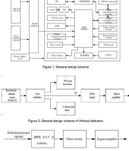
2.1. General Design Scheme
be used to carry out data detection, and equally the detected data were passed to mobile phones and personal computers through GPRS mobile data network [4].
The infrared detectors adopt the high-performance processing circuit of the sensor singals BISS001, the pyroelectric infrared sensor RE200B and the passive pyroelectric infrared switch made up of its peripheral circuits. The design scheme of infrared detectors is shown as Figure 2. The operational principle is to use the characteristic that any object exceeding absolute temperature will produce infrared spectrum to detect thieves into the rooms. The pyroelectric infrared sensor can receive infrared rays of radiation that have certain wavelength when bodies are moving. When thieves come into detecting areas, because its moving causes the changes of radiation fields in rooms, the pyroelectric infrared sensor RE200B detect infrared signals, and transfer them into faint electrical signals; when arriving to threshold level, the detectors output signals and send into input ends of one-level operational amplifier of BISS001 chip, at last pass through internal conversion and get into single chip to carry out processing [5-7].
The design scheme of glass fragment detectors is shown as Figure 3 it adopts the pressure sensor of high cost performance MPX4115 produced by Motorola company. The sensor adopts X-type resistance to replace Wheatstone bridge, which can avoid errors caused by mismatching resistances. The sensor induces the changes of pressure signals from the external world, the pressure signals are detected by the pressure sensor MPX4115A, and voltage signals are output from pin 1, then the signals pass through the filter circuit, the signal amplifier circuit, and reach single chip to process at last. When glass is broken, the buzzer will call the police, and signals are sent to personal computers or mobile phones through GPRS communication module to achieve monitoring in real time. The working voltage of pressure sensors is 501V, the working current is 7MA, the output voltage is 0.2-4.8V [8, 9].
2.2. Circuit of Hardware
The GPRS communication module in this essay is the communication module DL6200 produced by the world- famous producer and based on internet communicational mode, the module is used to achieve wireless data transmission in anti-theft system of smart homes. The data which are detected by infrared detectors and glass fragment detectors and dealt by the single chip are sent to mobile phones trough GPRS communication module, which make residents master the situations of rooms in real time. The working voltage of the module is 12V, interface RS485, emission current ≤12A, emission power ≤33dm+2dB, the module applies to the environment in the wild. Simultaneously the chips of GSM and GPRS are redeveloped to realize transparent transmission and TTL serial port communication. The fixed IP and AT commands are not needed to achieve the transmission and reception of signals.
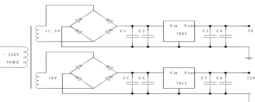
The essay adopts the amplifying circuit of single-ended input bridge. Its schematic diagram of circuit is shown as Figure 4. Because the voltage is very small, when the external signal detected by sensors are transformed to voltage signals ,the signal amplification circuit is needed to amplify signals, then the amplified signal are input to single chips to process. It is known from the circuit diagram.
The filter circuit which is used by the design scheme of infrared detectors and glass fragment detects adopts low-pass filter circuit of 2 orders voltage-controlled voltage sources. The schematic diagram of circuit is shown as Figure 5. Its main function is to strain off interference signals in the design schemes of infrared detectors and glass fragment detectors.
3. Results and Discussion
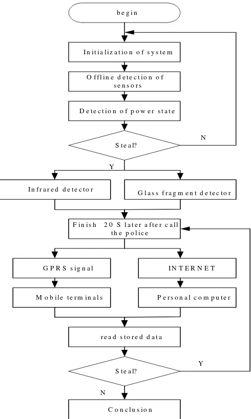
The design scheme in the essay adopts modular design the schematic diagram of design is shown as Figure 7. The collected data come from infrared detectors and glass fragment detectors, the two kinds of signals can be regarded as one switch value. When a detector detects data, the whole system will be open and judge whether there is a theft. When the judgment is that there is a theft, the alarm will be open. The data will be conveyed to mobiles of clients and personal computers of network terminals through GPRS and internet and by using TCP/IP agreement.
M CU AT89S52
GPRS com m unication
m odule
Under voltage testing
System failure testing
Debug port LCD
Reset circuit RS485 com m unication
channel Clock circuit
EEPROM Power supply
circuit
battery Error display
Signal am plifier Infrared
detector
Glass fragm ent detector
GPRS com m unication
network M obile term inals
PC INTER NET
buzzer I/O
Figure 1. General design scheme
Figure 2. General design scheme of infrared detectors
External pressure
signals MPX 4115 A
sensors
Signal amplifer Filter circuit
R1
Figure 4. Schematic diagram of signal amplifying circuit
+
Figure 5. Low-pass filter circuit
~ 2 2 0 V
b e g i n
I n i t i a l i z a t i o n o f s y s t e m
O f f l i n e d e t e c t i o n o f s e n s o r s
D e t e c t i o n o f p o w e r s t a t e
S t e a l?
F i n i s h 2 0 S l a t e r a f t e r c a l l t h e p o l i c e
I n f r a r e d d e t e c t o r G l a s s f r a g m e n t d e t e c t o r
G P R S s i g n a l
M o b i l e t e r m i n a l s
I N T E R N E T
P e r s o n a l c o m p u t e r
r e a d s t o r e d d a t a
C o n c l u s i o n
N
Y
S t e a l?
N
Y
Figure 7. Design scheme of software
4. Conclusion
Through the design and research about anti-theft control system of smart homes based on GPRS. The essay designs the general scheme of anti-theft control system of smart homes based on GPRS, the scheme of infrared detectors and glass fragment detectors, and designs the GPRS communication module in hardware circuit, the signal amplification circuit and the power supply circuit, etc. Simultaneously, the flow chart of software main programs is also design to achieve control. From the process of design, we can see that smart homes have a long way to go before they are fully developed. May the design can supply some theoretical help for the further study.
Acknowledgement
[2] Prakash A. A Comparison of Routing Protocol for WSNs: Redundancy Based Approach A
Comparison of Routing Protocol for WSNs: Redundancy Based Approach. Indonesian Journal of
Electrical Engineering and Informatics. 2014; 2(1): 48-55.
[3] Song XP, Liang Y, Zhang C, et al. Research on the Estimate on the Orientation of the Seismic
Signal Based on the Single Vector Vibration Transducer. Fire Control & Command Control. 2013;
38(5): 18-21.
[4] Su J, Yan ZG, Wu YC. Analysis on signal amplification process of basic amplifica tion circuits.
Modern Equipments in China. 2009; 74(4): 82-83.
[5] Cheng HL, Xu KK. A design scheme of smart homes. Information and Communication Sum. 2012;
118: 98-99.
[6] Wei R, Shen X, Yang Y. Urban Real-Time Traffic Monitoring Method Based on the Simplified
Network Model. International Journal of Multimedia & Ubiquitous Engineering. 2016; 11(3):
199-208.
[7] Su S, Wang S. Simple Monitoring Network System of Wireless Sensor Network. Bulletin of Electrical
Engineering and Informatics. 2012; 1(4): 251-254.
[8] Gang Li, Xiaofeng Zhao, Dianzhong Wen, Yang Yu. Research on Silicon-based Planar Spiral
Inductance Coil Based on Microelectromechanical System. TELKOMNIKA (Telecommunication
Computing Electronics and Control). 2015; 13(4): 1127-1132.
[9] Chang M, Wang Q. Application of Wireless Sensor Network and GPRS Technology in development
of Remote Monitoring System. TELKOMNIKA Indonesian Journal of Electrical Engineering. 2015;