Proceedings of DET2008 5th International Conference on Digital Enterprise Technology Nantes, France 22-24 October 2008
DEVELOPMENT OF AN OPEN SOFT CNC SYSTEM
BASED ON STEP-NC AND FUNCTION BLOCKS
M. Minhat
The University of Auckland, NZ [email protected]
Xun W. Xu
The University of Auckland, NZ [email protected]
V. Vyatkin
The University of Auckland, NZ [email protected]
ABSTRACT
Modern manufacturing industries have put on increasing demands on computer numerical controllers (CNC) for it to be able to work with and process higher level input data described using languages such as STEP-NC, rather than the outdated G-codes. The research work described in this paper is about the development of a soft CNC controller that can process STEP-NC (ISO 14649) data. Function blocks (IEC 61499) are also used as the interface between the STEP-NC data model and the controller. The layered STEP-NC/FB architecture is proposed, which simplifies the design of the controller with layers responsible for data processing, data storage and execution. With the object-oriented, Model-View-Control design pattern, the STEP-NC/FB architecture supports the design framework, in which simulation of the machining becomes a natural and inherent part of the design process, with seamless transition from simulation to actual machining.
KEYWORDS
CNC, STEP-NC, Function Blocks, Controller
1. INTRODUCTION
In simple terms, open CNC architecture can be understood as having standard hardware and software which permit system scalability, and ensure future performance enhancement. The development of an open CNC architecture entails the establishment of a type of software architecture that fits in with a “general” computer which is independent of a control vendor, plus a communication standard among computer hardware, an operation system and application software (Liu et al, 2006 and Michaloski et al, 1998). The driving force for an open CNC architecture has been the requirement of an agile production and autonomous CNC control for
modern manufacturing industry (Suh et al, 2002 and Newman et al, 2007).
minicomputers, often running in a DOS or UNIX environment and with Real-Time Dynamical Linked Library (RTDLL) functionalities (Liu et al, 2006). The added advantage of using modern high-speed, consumer-grade Personal Computers (PCs) is that the controllers can be easily made “network-fit”.
Work concerning open CNC architecture has been one of the main topic areas in CNC research activities since the mid 1980s, but it was not until the early 1990s that a few commercial products were investigated and prototyped by some leading companies in the CNC industry (Birla et al, 1996 and Michaloski et al, 2004). World-wide, three industrial consortiums have been active since the early 90’s. They are the Open System Environment for controllers (OSE) of Japan (Zhang et al, 2003), the Open System Architecture for Controls within Automation systems (OSACA) of Europe, and the Open Modular Architecture Controllers (OMAC) consortium of the USA. Though different approaches are used, they all share a similar vision of using open-architecture controllers in replacement of the current closed CNC systems.
It is also fundamental for an open architecture system to comply with industrial standards and/or de facto industrial standards (Wang et al, 2004). Some resistance is visible among the CNC original equipment manufacturers (OEMs), as their system architectures are proprietary in nature. There is reluctance to release the information needed to design a successful interface (Rober and Shin, 1995).
This article describes a soft-CNC with an open architecture that works on a PC. This soft-CNC can be used to test various STEP-NC data files without having to resort to a physical machine tool. To ensure the openness of the open architecture CNC system, the following implementation technologies are used,
(i) Object-oriented structure
(ii) Dynamic modelling using Finite State Machine (FSM)
(iii) Use of Function Block technology
(iv) Employment of a Model-View-Control (MVC) design pattern.
The rest of the paper will discuss the distributed structure of the developed soft-CNC. Three types of machining features (i.e. including Planar_Face, Drill_Hole and Pocket1) have been tested. The overall structure of the controller and its modular functions are also discussed.
2. STEP-NC AND FUNCTION BLOCK
In the 21st century, two new standards emerged, ISO14649 known as STEP-compliant numerical control (STEP-NC) and IEC 61499 function blocks.
The Application Reference Models (ARM) of STEP-NC has been published in various parts, e.g. ISO 14649-1 (2003, ISO 14649-10 (2004), ISO 14649-11 (2004) and ISO 14649-111 (2003).
STEP-NC serves as an extension of STEP to NC, allowing an integrated environment between CAD/CAM and CNC (Xu et al. 2005, Xu and Newman, 2006). The information contained in a STEP-NC file is divided in three subsections:
• workplan executables; • technology description; • geometry description;
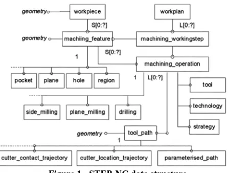
Workplan is characterized by a series of executables whose order may be pre-established, or dependent on the actual machining conditions. There are three types of executables. They are Workingsteps, CNC functions and part program structures. Among them, Workingsteps are the most important executable. They define machining operations together with machining features (Figure 1).
Figure 1 - STEP-NC data structure
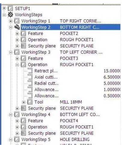
Figure 2 – A tree-view of STEP-NC entities
In the early 2005, International Electrotechnical Commission (IEC) published IEC 61499 (2005) that standardizes some aspects of the application of software modules called ‘function blocks’ in distributed industrial-process measurement and control systems (IPMCS). The IEC-61499 function block specifications provide a new standard to meet the requirements based on an explicit event-driven model and also provide data flow and finite-state automata-based control (Dubinin and Vyatkin, 2007). Function blocks are grouped into two types, Basic function blocks and Composite function blocks. A Basic function block defines the fundamental functional relationships of events and data. A Composite function block is a combination of several Basic function blocks which look just like a ‘normal’ function block from the outside (Zoilt et al, 2007). The algorithms can be written in either high-level programming languages (e.g. Java) or in the IEC 61131 languages (Proctor et al, 2001) for programmable controllers (e.g. Component-Based). Previous research on function blocks proved that they can be used as the enabler to encapsulate process plans, integrate with a third-party dynamic scheduling system, monitor the process plan during execution, and control machining jobs. They are also suitable for machine level monitoring, shop-floor execution control and CNC control.
Figure 3 shows a typical function block. It is separated into an upper and a lower part. At the
upper part the event inputs and outputs are drawn. The data inputs and outputs are drawn at the lower part. In the machining example, ‘Axis’ is modeled as an input variable and connected to ‘Execute’ like all other data inputs.
Figure 3 - An FB conforming to IEC 61499
In order to make it easy to implement function blocks for event driven systems, event inputs and event outputs are used. Both data inputs and outputs are explicitly connected to an event input or event output respectively.
Both STEP-NC and function block technology are used in the development of the soft-CNC system.
3. SYSTEM STRUCTURE
The architecture of the proposed system contains four basic functional modules,
(i) Data Input Model
(ii) STEP-NC to FB Translator (iii) Tool Path Generator
(iv) Embedded CNC-FB STEP-NC Controller
Figure 4 - Basic functional modules of the soft-CNC
The modules of Setup Process Planning (SPP), Machining Feature (MF) and Tool Path Data (TPD) are responsible for product data parsing; setup planning, machining feature sequencing, scheduling integration and function block execution control. The Motion Control/Process Execution (MCPE) and Physical Output (PO) modules deal with Workingsteps at a detailed level for each machining operation, which include decisions to be made on cutting tool selection, machining condition assignment, tool path generation and machining code generation.
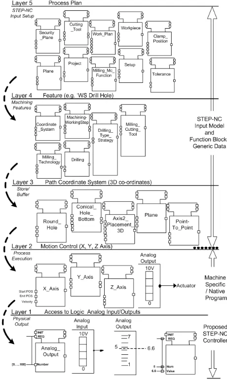
Function blocks are used for data processing and execution control within the soft-CNC system. A five-layer structure is suggested consisting of Setup Process Planning (SPP), Machining Feature (MF), Tool Path Data (TPD), Motion Control/Process Execution (MCPE) and Physical Output (PO). This layered structure helps separate the generic process data from the machine-specific data. This is shown in Figure 5.
Within soft-CNC, machining features (MFs) are used as information carriers from SPP to PO. MFs are those shapes such as Planar_Face, Drill_Hole and Pocket1 that can be easily produced by the available resources and machining technologies. Each machining feature holds a set of loosely coupled information about how to fabricate itself, such as machining sequence, cutter type, tool-path generation logic and cutting conditions. Appropriate library and sequenced machining features are then packed into function blocks to generate a machine-neutral tool path. This generic tool path needs to be created only once. Other machine-specific information is derived at runtime by an open CNC controller after the generic tool path (a set of function blocks) is transmitted to the STEP-NC controller. The controller is knowledgeable of the real-time status and the dynamics of the machine being controlled.
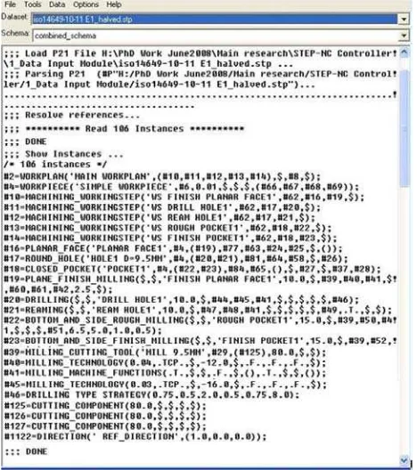
3.1 Data input model
The design flow starts with the development of a STEP-NC data model describing the part to be manufactured. The STEP-NC input file (Part 21 physical file) (ISO 10303-21, 1994) contains both design and machining data that are correlated to other necessary information in part programming, such as tooling requirements, feature parameters, feature geometry, feature tolerances, strategy and technology information. Data Input Model generally consists of two divisions: generic data (machining method, machining sequence and machine tool data) and machine-native information (cutting tool data, cutting conditions and tool paths).
Then the STEP-NC to FB translator generates the equivalent function block models, which can be manually modified using the Function Block Editor. A basic function block can have multiple outputs while maintaining internal hidden-state information. This means that a function block can generate different outputs, even if the same inputs are applied. This functionality is of vital importance for dynamically adjusting cutting parameters and generating tool paths after a function block is dispatched to a CNC controller. This is of course done by changing the internal state of the function block. For example, a function block of Pocket1 can be used for roughing and finishing at the same machine or at different machines, with different cutting parameters and/or tool paths, by adjusting the internal state variable of the function block to fine-tune the algorithms in use. The behaviour of a function block is maintained by its execution control chart (ECC). The function block model is structured according to the object-oriented Model-View-Control (MVC) design pattern (Christensen, 2000). The generation of tool path is later carried
out by the STEP-NC to FB Translator and Tool Path Generator Module, which are capable of direct execution of function blocks. The key software components used to implement the architecture are discussed in the following subsections.
3.2 STEP-NC to FB translator
Kramer et al (2006) defined an NC interpreter as a software system that translates a program as it reads it and turns it into instructions or codes. A compiler will translate the codes into an intermediary form, and then invoke a linker, which turns the object file into an executable program to produce commands to run a machine.
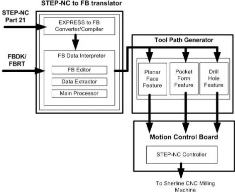
The STEP-NC to FB translator developed in this research reads the entire program before starting execution. This is so that the entire data model can be established at the offset. Also, to a much greater extent than G-code (ISO 6983-1, 1982) and post-processor, the STEP-NC to FB translator also helps generate tool paths. Figure 6 below shows a simplified structure for the STEP-NC to FB translator.
Figure 6 - Structure for the STEP-NC to FB translator
The translator has four parts. The data extractor and the main processor are similar to those of other similar STEP-NC controllers. The other two parts, the converter and the editor, are unique in the developed soft-CNC system.
the data extraction, creation and edition work in
progress. 3.3 Tool path generator
This module is linked to FB Editor in the STEP-NC to FB translator. TPG is composed of several subroutines which implement tool path generation for the machining features such as Planar_Face, Drill_Hole and Pocket1. At this stage of research the tool path generation is still done manually.
In the FB editor, the interpreted data are converted into new command codes according to the required tool path. The tool path information in the STEP-NC data structure is optional and in most cases, it is not given. Therefore, tool path generation capability needs to be built into this soft-CNC. TPG generates the tool path for machining of each workingstep. Four segments of tool path are involved. They are approach, machining, retract, and departure. TPG generates the tool path for each segment based on the machining strategy, e.g. ‘spiral-in’ tool approaches, and ‘X-direction’ machining path as specified by the STEP-NC date file.
A different machining strategy will lead to different tool path. The module enables manual selection of a machining strategy. It can also design the tool path for each feature using the extracted geometry information and machining strategy. Figure 7 – Data extractor by the translator
In order to handle data files written in the FB format, an FB editor is developed and incorporated into the translator. The data written in FB are consistent with the STEP-NC data structure (schema). To prevent erroneous operation and offer a more convenient working method, the FB editor adds or deletes entire lower branches. For example, if the operator adds a new machining Workingstep to the Workplan, the FB editor adds all subsequent entities such as feature and operation entities.
As an example, Figure 8 shows the tool path generated for a Planar Face cutting. A Planar Face as specified in STEP-NC contains the following parameters:
• feature_placement : Ref-Direction_Y; • depth : -5 mm;
• course_of_travel, specified along the X-direction: distance 60 mm;
• face_boundary; The translator together with the intelligent
controller is programmed using Java™. In this project, we used Function Block Development Kit (FBDK), a Java-based tool, originally developed by the Advanced Technology Division of Rockwell Automation (currently supported and distributed by HOLOBLOC, Inc. (USA)). It contains a graphical Function Block Editor, which is effectively an integrated development environment that supports graphical development of function blocks and systems and their translation to Java™ classes. The Function Block Run-Time (FBRT) complements the editor with the ability to execute the compiled function blocks. The latter can be executed on any computer that supports the Java™ Virtual Machine.
• removal_boundary, specified as a profile length: 50 mm.
Based this information, the module generates the required sequences of segments the cutting tool has to follow to completely machine the planar face. This sequence together with the feed-rate data is stored in a file that the soft-CNC uses to send signals to the motor drives. The tool path generator module has two functionalities, tool-path generation and simulation. Machining simulation is an important feature of this soft-CNC as there is no hardware setup required for testing.
The intention of the future soft-CNC system is for it to generate tool paths automatically for various machining features.
Figure 8 – Tool path generated for a Planar Face milling
3.4 The controller
The controller has intelligence built into it to make decisions based on the given STEP-NC input data in the FB file in the early stage of operation. When the controller gets the raw STEP-NC data in an FB file, it decides whether the current machining Workingstep is capable of guaranteeing the accuracy or surface roughness, and decides if additional finishing operations are needed. By the same token, if the tolerance requirements are not as stringent, the controller may “relax” on some of the machining operations. After modification, the changed data are saved in another FB file. The system will be connected to the Internet and/or Web-server, so that the data can be shared with another PC. With this feedback from the controller, the part program for production is confirmed and updated. Afterwards, the controller can either verify through simulations or start machining.
4. DEVELOPMENT OF THE SOFT-CNC
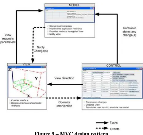
The soft-CNC system is developed based on the extension of the Model-View-Controller design pattern adapted by Christensen (2000) which is explained in details in the next section. MVC classes in this system are represented by IEC 61499 function block types. The CNC milling machine and STEP-NC controller are built so that it includes several system configurations corresponding to the stages of the design process.The physical framework proposes a data model based on STEP-NC standards implemented in the prototype controller system. Figure 9 shows the framework of the soft CNC system. It consists of (a) Model, (b) View and (c) Controller.
Figure 9 – MVC design pattern
The model layer reads and writes content to the database and converts it into programmable objects that are processed by the controller layer to carry out the application functionality and to pass on for display in the view layer. The view layer is the templates or interface that the operators see and interact with. The controller consists of a front controller and related action code to route, filter and process the data input and to trigger machine data application.
interact with the application by posting request and receiving responses via the software program (FBDK/FBRT). The entire MVC design architecture (system application, devices and resources) can be distributed over multiple tasks and events and it can be run on a single, stand-alone PC. STEP-NC data are object-oriented and also of a hierarchical structure with a predominantly top-down inheritance. In this research, STEP-NC data are represented as functional units that correspond to layered function block architecture. In this architecture, each layer is designed to utilize the services of the lower one. Communications between the layers are implemented by the communication function blocks Publish and Subscribe.
For example, machining features are implemented by a library of corresponding function blocks that parameterize machining features and machining data. Subsequent function blocks generate the tool paths required for the respective features. Other function blocks are used for managing features and shape coordinates to accept or collect data entered either manually by user, or automatically from other data sources. In fact, the very first set of data translated from a STEP-NC data model are related to set-up initialization, which include:
•
Machine Coordinate System (the maximum travel displacement of each axis).•
Workpiece (dimensions)•
Workpiece Coordinate System (Workpiece origin)•
Path Coordinate System (Tool start point-home positions).4.1 Detail system configuration
According to the MVC pattern the simulation software configuration is a composition of three types of modules: Model, View and Controller. The use of this pattern allows a seamless transition from the simulation software configuration to the real control of physical machinery.
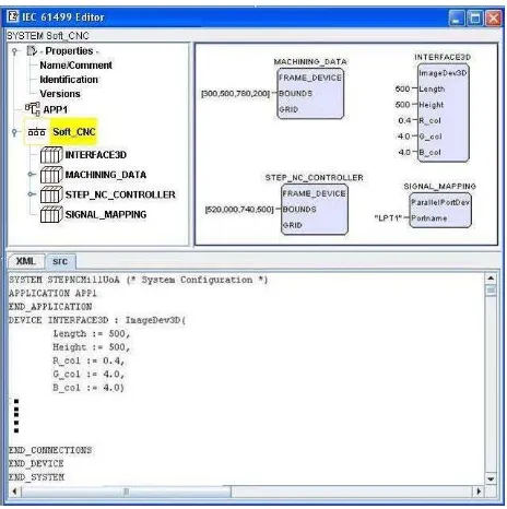
Figure 10 shows the system configuration that consists of four devices (in IEC 61499
terminology): MACHINING_DATA, INTERFACE3D, STEP_NC_CONTROLLER and
SIGNAL_MAPPING, the first three corresponding to Model, View and Control as in the MVC pattern.
Figure 10 – Soft-CNC system configuration
The elements of the configuration are as follows:
(i) Machine modelling is done by taking into account machine’s structure, its physical dimensions, number of axes available and the type of inputs, outputs and movement expected. This module is allocated to a separate execution container (Device in the FB terminology). The MACHINING_DATA device is further subdivided onto seven finer grain execution containers (resources):
‘Setup_1’, ‘Security_Plane’, ‘Clamping_Positions’, ‘Tolerance’,
‘Milling_Cutting_Tool’,
‘ModelControllerResponse’, and ‘Model3D’ types, containing the function block applications, for modelling the machine coordinate system (MCS), workpiece dimension, tool travel limits, workpiece coordinate system etc based on STEP-NC data model.
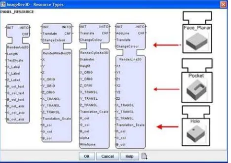
(ii)The View module is to render the status of the model or to provide visualisation. In the
‘Soft-CNC’ system configuration, the
INTERFACE3D device contains one instances of the specialized ‘ImageDev3D’ resource type; it provides some very basic viewing elements for milling operations. (iii)The Control module, implemented in the
outputs the signal to the motor drive axes to execute the machining sequences.
At the moment, the system only uses wireframe models for graphical visualisation. The cutting tool is represented by a cylinder. Lines represent the tool path. The INTERFACE3D visualization simulates what one would expect of the milling machine. This allows for a preview of the controller motion, and can be used as a verification method. The function block runtime software runs on a PC and enables the execution of the system. The very same code can of course run on embedded devices capable of supporting Java™.
Based on the design data of a part, the corresponding function block application is generated. The STEP-NC data are translated into parameters of the corresponding function blocks. The geometry of the machining feature is represented as sequences of coordinate points which are then stored. Movement between the points is implemented by the motion controller function blocks types, which will calculate an output to the axes motors from the sampled positions, generated by the calculated trajectory points.
The entire process goes as follows. It starts with the STEP-NC data model of a part that is represented by the BTN_ADD function blocks type. It is then translated to the function block application
Control (allocated in the “STEP_NC_CONTROLLER” device). Execution
containers (resources in IEC 61499 terminology) are used to separate these data out into distinct tasks consists of the machine (travel dimensions); Workpiece (dimensions); Workpiece_Start; and Tool_Start.
The “Model” device contains the function block application, modelling uncontrolled behaviour of the machine tools. Given input control signals the model changes its state as the real machine tool does. It feeds the parameters of the current state to the device INTERFACE3D which can render FB applications.
4.2 Interface with actuators and visualisation
With minimal changes, the soft-CNC will be able to execute on any computing platform supporting the IEC 61499 function blocks: from a personal computer with direct peripheral connection connected to a machine tool, to an embedded device with a distributed architecture. In the latter case, the motor drives, corresponding to the three axes and the display are connected to the main processing unit via a field area network (fieldbus).
In fact, the system has been implemented using a PC controlled CNC milling machine, a three-axis mill which was originally supplied with a PC-based EMC controller and a motor control unit that drives three stepper motors. The motor control board is connected to the PC via a parallel port. In this configuration, only a direction signal and a single pulse will be required to activate the motor in a given direction. The desired behaviour of physical interface is to utilize the raw data calculated in the controller (in terms of feed rate) to control the real machine (i.e. to produce the signals required to drive the motors).
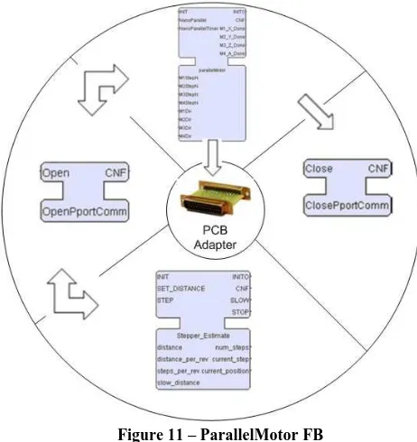
In this particular system, interfacing with hardware is dealt with by creating an abstract device model, called ParallelPortDev. The implementation of the device relies on the RXTX library, providing programming access to the hardware. The device model allows a specific library of function blocks to provide user interfaces to the motor drives via the parallel port of the PC. The access process includes opening the parallel port stream and calculating the required direction and number of steps to traverse. This is communicated to the Parallel_Motor function block (Figure 11), which generates the required output sequence of data to execute the motor control, and in turn drives the motors on the machine. At the completion of the sequence the parallel port stream is closed.
Figure 11 – ParallelMotor FB
Geometrical parameters of the features are used as input parameters in the corresponding function blocks. The workpiece data model will provide point-to-point connection to simulate the Tool Path Generator. The controller needs to generate two types of signals: target signals and velocity signals. Target signals correspond to the coordinates (X, Y, and Z) of a destination, and the velocity signals represent the feed rate of each axis.
The visualisation component of the MVC-based architecture of the Soft-CNC is implemented in a 3D virtual environment through the Java™ extension, Java3D. The developed visualisation engine can render workpieces and cutting tools. Travel constraints and axes relationships are also modelled. The engine is accessible through the ImageDev3D device, and utilizes a library of rendering function block types such as
RenderAxis3D, RenderWireBox3D, RenderCylinder3D and RenderLine3D. 3D
rendering is achieved in a three-step process. First a JFrame object is extended to support 3D rendering. This is done by creating a 3D Universe within it. JFrame itself is a native object in the 2D library Java.Swing, and handles the creation of a window object in which to render. Next, an interface to the function block environment is created. This interface is called the ImageDev3D. This is encapsulated as a function block device (as it represents a separate subsystem). An extended JFrame object is added as a child of the ImageDev3D. In the final step, separate function blocks are created that define a particular shape. These function blocks construct Shape3D objects which can be rendered in the 3D Universe. The geometric data are transferred to the JFrame that exists in the ImageDev3D. The entire process is depicted in Figure 12. In this way it is possible to render multiple instances of any shape, as long as there is a function block for each instance. Furthermore it allows other more complex geometries to be created with ease.
Figure 12 - Visualisation through the ImageDev3D rendering process
Each shape added to the 3D Universe is coupled with a transform object that allows a user to manipulate the translation, rotation and scale of the shape. Modifying the transform object allows dynamic motion of a shape without comprising the original shape data. In addition the 3D visualization supports some typical navigation abilities as seen in many other 3D packages–namely rotate, zoom and pan. This enhances the user-friendliness of the interface.
5. CONCLUSIONS
The developed soft-CNC can provide a viable platform for testing STEP-NC programs. Use function block concept has at least two significant benefits. It can make simulation as an intrinsic part of the system. This is done through the “Model- View-Controller” design pattern. Secondly, it is easy for the system to later on to be “hooked up” with a physical machine tool as long as the embedded devices are function block- enabled, or even capable of supporting Java™.
The system also has an open structure and runs from a set of high-level data, i.e. STEP-NC. This data are advantageous over the traditional G-code in that more design information can be made available to the machining process. This study also proves that STEP-NC and function block can work hand in hand in developing an open control system for machining purposes.
The work reported in this paper is still ongoing. The main focus in the near future is on automatically interpreting STEP-NC data for construction of function blocks, and further enhancement of the graphic user interfaces.
Acknowledgment
The authors wish to acknowledge the contributions from S. Wong and Z. Al-Bayaa who assisted in developing the initial function block program.
REFERENCES
Birla, S., Egdorf, H., Igou, R. E., Michaloski, J. L., Sweeney, D. J., Uchida, D., Weinert, G. & Yen, C. J., “An Open Architecture Model of System Development”, ASME International Mechanical
Engineering Conference and Exposition (Atlanta,
GA). 1996
Christensen, J. H., “Design patterns for systems engineering with IEC 61499”. Conference
Dubinin, V. & Vyatkin, V., “On Definition of a Formal Semantic Model for IEC 61499 Function Blocks”,
Journal of Embedded Systems, 2007
http://www.arcweb.com/omac http://www.osaca.org
IEC 61499. Function blocks for industrial-process measurement and control systems - Part 1: Architecture. 2005
ISO 6983-1. Numerical control of machines—program format and definition of address words—Part 1: data format for positioning, Line motion and contouring control systems. 1982
ISO 10303-21. Industrial automation systems and integration – Product data representation and exchange – Part 21: Implementation methods: Clear text encoding of the exchange structure. 1994
ISO14649-1. Industrial automation systems and integration—Physical Device Control—Data model for computerized numerical controllers—Part 1: Overview and fundamental principles. 2003
ISO14649-10. Industrial automation systems and integration—Physical device control—Data model for computerized numerical controllers—Part 10: Data model for computerized numerical controllers—Part 10: General process data. 2004
ISO 14649-11. Industrial automation systems and integration -- Physical device control -- Data model for computerized numerical controllers -- Part 11: Process data for milling. 2004
ISO 14649-111. Industrial automation systems and integration -- Physical device control -- Data model for computerized numerical controllers -- Part 111: Tools for milling machines. 2003
Kramer, T. R., Proctor, F., Xu, X., and Michaloski, J. L., “Run-time interpretation of STEP-NC: Implementation and performance”, International
Journal of Computer Integrated Manufacturing, Vol.
19, No. 6, 2006, pp 495-507
Liu, T., Wang, Y. & Fu, H., “The open architecture CNC system HITCNC based on STEP-NC”, Proceedings of
the World Congress on Intelligent Control and Automation (WCICA), 2006, pp 7983-7987
Michaloski, J., Birla, S., Weinert, G. & Yen, C. J., “Framework for component-based CNC machines”,
Proceedings of SPIE - The International Society for Optical Engineering, 1998, pp 132-143
Michaloski, J. L., Soons, J. A. & Proctor, F. M., “Accessing the performance of model-based control in a distributed machine tool control environment”,
ASME International Design Engineering Technical Conferences (Salt Lake City, Utah, USA). 2004
Newman, S. T., Nassehi, A., Xu, X. W., Jr, R. S. U. R., Wang, L., Yusof, Y., Ali, L., Liu, R., Zheng, L., Kumar, S., Vichare, P. & Dhokia, V. “Interoperable CNC for Global Manufacturing”, Flexible Automation
and Intelligent Manufacturing (FAIM2007)
(Philadelphia), 2007, pp 1-13
Proctor, F., Michaloski, J., Birla, S. & Weinert, G., “Analysis of behavioral requirements for component-based machine controllers”, Proceedings of SPIE - The
International Society for Optical Engineering, 2001,
pp 10-18
Rober, S. J., and Shin, Y. C., "Modeling and control of cnc machines using a PC-based open architecture controller." Mechatronics, Vol. 5, No. 4, 1995, pp 401-420
RXTX Java Library (2008), Online: http://users.frii.com/jarvi/rxtx/index.html, accessed January, 2008
Suh, S. H., Chung, D. H., Lee, B. E., Cho, J. H., Cheon, S. U., Hong, H. D., and Lee, H. S., “Developing an integrated STEP-compliant CNC prototype”, Journal
of Manufacturing Systems, Vol. 21, No. 5, 2002, pp
350-362
Wang, S. H., Wang, Y. Z., Lu, H. & Han, Z. Y., “Design of soft CNC system with a new open-architecture”,
Jisuanji Jicheng Zhizao Xitong/Computer Integrated Manufacturing Systems, CIMS, Vol.10, No.2, 2004,
pp 200-204
Xu, X. W., Wang, H., Mao, J., Newman, S. T., Kramer, T. R., Proctor, F. M., and Michaloski, J. L., “STEP-compliant NC research: The search for intelligent CAD/CAPP/CAM/CNC integration”, International
Journal of Production Research, Vol. 43, No. 17,
2005, pp 3703-3743
Xu, X. W., and Newman, S. T., “Making CNC machine tools more open, interoperable and intelligent - A review of the technologies”, Computers in Industry, Vol. 57, No. 2, 2006, pp 141-152
Zhang, C., Wang, H., and Wang, J., "An USB-based software CNC system." Journal of Materials
Processing Technology, 139(1-3 SPEC), 2003, pp
286-290
Zoilt, A., Strasser, T., Hall, K., Staron, R., Surender, C. & Favre-Bulle, B., “The past, present, and future of IEC 61499.” Lecture Notes in Computer Science
(including subseries Lecture Notes in Artificial Intelligence and Lecture Notes in Bioinformatics),