ABSTRACT
ABSTRAK
ACKNOWLEDGEMENT
TABLE OF CONTENTS
CHAPTER 2: LITERATURE REVIEW
2.0 Introduction 5
2.1 Design for Environment 5
2.1.1 Objective of DFE 7
2.1.2 Approaches to optimal environment performance 8
2.1.3 The new DfE Process 9
2.1.4 DFE benefits 11
2.1.5 Analysis of DfE Process/ DfE Tools 11 2.1.5.1 Guidelines and Checklist Document 12
2.1.5.2 Use of Flow Charts 13
2.1.5.3 Use of Matrices 14
2.1.5.5 Environment Conscious Quality Function Deployment 17
2.2 Design for disassembly (DfD) 18
2.3 Design for Recycling and Reused 20
2.4 Green technology 21
2.5 Green manufacturing 23
2.6 Sustainability 24
2.6.1 Design 24
2.6.2 Design for Sustainability 25
2.6.3 Implementing sustainable design 26
2.6.4 Barriers to Sustainability 27
2.6.5 Concepts and Tools for Sustainable Design 28 2.6.5.1 Closed-loop or Closed-cycle Design 28 2.6.5.2 Life-cycle Analysis (LCA) 28 2.6.5.3 Sustainable Manufacturing 29 2.6.5.4 Sustainable Manufacturing Standards 30 2.7 Environmentally Responsible Product Development 31 2.7.1 Decision Production Systems 32 2.8 Conceptualizing a Medical Need 33
2.9 Material selection 34
2.9.1 PVC 35
2.9.1.1 PVC in medical items 35
2.9.2 Polycarbonate 37
2.9.2.1 Medical Applications 38
2.10 Dialysis 39
CHAPTER 3: METHODOLOGY
3.0 Introduction 41
3.1 Process Flow Chart 41
3.1.4 Design Methodology for Structural Analysis 44
3.1.5 Result and Discussion 45
3.1.6 Conclusion and recommendation 45 3.1.7 Report Writing and Submission 45
3.2 Phases of DFE Analysis 46
3.2.1 Analyzing of Product (Sustainability analysis) 47
3.2.1.1 DFE Analysis Flow 47
3.2.1.2 Environmental Impact 48
3.2.2 Assessment of environmental performance 49
CHAPTER 4: RESULT AND DISCUSSION
4.1 Introduction 51
4.2 Current product 51
4.2.1 Product Specification 52
4.2.2 Exploded view 53
4.3 Material Analysis on dialyzer Product 53
4.3.1 Case part analysis 54
4.3.2 Cap part analysis 55
4.3.3 End caps part analysis 56
4.4 Material Selection for Sustainable Product 58 4.5 Material Choice for Sustainable dialyzer 62
4.5.1 Sustainable Product Part 67
4.5.1.1 Case/body 67
4.5.1.2 End caps 72
4.5.1.3 Cap 76
4.5.2 Summary for sustainable dialyzer 81
4.6 Life Cycle Assessment (LCA) 81
4.6.1 Life Cycle Assessment of HDPE dialyzer 83 4.6.2 Life Cycle Assessment of Polycarbonate dialyzer without reused 84 4.6.3 Comparison of Life Cycle Assessment of PC dialyzer and
4.6.4 Life Cycle Assessment of Polycarbonate dialyzer with reused 87 4.6.5 Comparison of Life Cycle Assessment of PC dialyzer
and PC dialyzer reused 89
4.7 Sustainable design and material of dialyzer 94
CHAPTER 5: CONCLUSION AND RECOMMENDATION
5.1 Conclusion 97
5.2 Recommendation 98
REFERENCE 99
LIST OF FIGURES
1.1 Article San Francisco Chronicle 3
2.1 Objective and Characteristics of DFE 7 2.2 Main phases of product life cycle and flow of recourses 8 2.3 Combined Safety and Environmental Review Process 10
2.4 Example DfE checklist question 12
2.5 Example of flow chart questions 14
2.6 Product design matrix 15
2.7 Life Cycle Approach as basis for modeling systems 16 2.8 DfE flow and design support tools 18
2.9 Green technology subject areas 22
2.10 The Shift to Sustainable Design 24
2.11 Sustainability and the Design Funnel 25 2.12 Relationship between sustainable development, sustainability,
and green engineering 26
2.13 Product development organization with isolated environmental
decision-making 33
2.14 Design of this safety syringe allows healthcare practitioners
to operate the device with one hand. 35
2.15 Polycarbonate resin 37
2.16 Dialyzer 39
2.17 Hemodialysis schematic 40
3.1 Process flow in conducting PSM 1 & PSM 2 42
3.2 Phases of analysis 46
3.3 Process flow in conducting sustainability analysis 47
3.4 Pie chart 48
3.6 Powerful analytical features on many levels 49 3.7 Interactive analysis of a network 50 3.8 Comparison (damage assessment) analysis of a human health,
ecosystem quality and resources 50
4.1 Dialyzer 52
4.2 Exploded view of dialyzer 53
4.3 The graph analyze view of Case 54
4.4 The graph analyze view of Cap 55
4.5 The graph analyze view of End cap 56 4.6 Pie Chart Environmental Impact of ABS case 68 4.7 Pie Chart Environmental Impact of PC case 69 4.8 Pie Chart Environmental Impact of HDPE case 70 4.9 Pie Chart Environmental Impact of ABS end caps 73 4.10 Pie Chart Environmental Impact of PE High Density end caps 74 4.11 Pie Chart Environmental Impact of HDPE cap 77 4.12 Pie Chart Environmental Impact of PP cap 78 4.13 Pie Chart Environmental Impact of PC cap 79
4.14 Tree Diagram of HDPE dialyzer 83
4.15 Tree Diagram of PC dialyzer without reused 84 4.16 Comparison PC dialyzer and HDPE dialyzer (weighting) 85 4.17 Comparison PC dialyzer and HDPE dialyzer (single score) 86 4.18 Tree diagram of PC dialyzer reused 88 4.19 Comparison PC dialyzer and PC dialyzer reused (weighting) 89 4.20 Comparison PC dialyzer and PC dialyzer reused (single score) 90 4.21 Solid Waste Management Hierarchy 91 4.22 Comparison HDPE, PC and PC dialyzer reused (damage assessment) 91
LIST OF TABLES
3.1 Descriptions of the ECQFD structure 63
4.1 Summary of the result from XRD 57
LIST OF ABBREVIATIONS, SYMBOLS, SPECIALIZED
NOMENCLATURE
ABS - Acrylonitrile butadiene styrene
CML - Centre of Environmental Sciences at Leiden University
Cu - Copper
DEHP - Di-(2-ethylhexyl) phthalate DFA - Design for Assembly DfD - Design for disassembly DfE - Design for Environment
ECQFD - Environmentally Conscious Quality Function Deployment EEA - Assessment or Environmental Effect Analysis
EIO-LCA - Economic Input-Output LCA EM - Engineering Metrics
EMS - Environmental Management System EPA - Environmental Protection Agency
ERPD - Environmentally Responsible Product Development EtO - Ethylene Oxide
FDA - food and Drug Administration GWP - Global Warming Potential HDPE - Polyethylene High Density
ISO - International Organization for Standardization
JEMAI - Japan Environmental Management Association for Industry QFDE - Quality Function Deployment for Environment
KG - Kilogram
LDHE - Polyethylene Low Density
MJ - megajoules
N - Nitrogen
OEM - Original Equipment Manufacturer
OHSAS - Occupational Health & Safety Advisory Services PB-EMS - Product-based Environmental Management Systems
PC - Polycarbonate
PE - Polyethylene
PP - Polypropylene
PVC - Polyvinyl chloride or vinyl TDI - Tolerable Daily Intake
TRACI - Tool for the Reduction and Assessment of Chemical VOC - Voice of Customer
XRD - X-ray diffraction
CHAPTER 1
INTRODUCTION
1.0 Background
Design is key to the function, meaning, and appeal of products used by people every day throughout the world (Kurk F. et al., 2004). It has been recognized as a critical stage for determining costs and profitability. The National Research Council estimates that 70 percent or more of the costs of product development, manufacture, and use are determined during initial design stages (Kurk F. et al., 2004). For those who bring shape to our physical world by designing products, it is also an unparalleled window of opportunity to distinguish products, while championing the environment through innovation.
Exactly what draws consumers to pick up a product or just to want it is sometimes referred to as “Factor X.” While this factor can be elusive, a common element of good design is satisfaction of the core needs of the user. Hence meeting these needs with unique, will assists in improving the design as well as to differentiate products in the marketplace.
(www.epa.gov/). Several non-regulatory, voluntary initiatives on safer chemical synthesis, comparative risk analysis, and alternative technology development merged to create the EPA's Design for Environment (DfE).
1.1 Objectives
The objectives of this study are:
1) To investigate the design parameters of medical product.
2) To analyze the medical product using Design for Environment analysis. 3) To purpose the medical product base on Life Cycle Assessment.
1.2 Scope
The scope of this study is to focus on analyzing medical product based on DFE guidelines, methods, and tools obtained through the literature studies. This research also includes the environmental impact and performance of the product evaluated with Solidwords (Student Vision) and SimaPro which is this software for LCA studies. As for the boundary, the analyses only cover the external feature of the dialyzer (case, end cap, and cap).
1.3 Problem Statement
simply dumped all waste streams together, from reception-area trash to operating-room waste, and burned them in incinerators. Incineration is a leading source of highly toxic dioxin, mercury, lead and other dangerous air pollutants such as in Article San Francisco Chronicle showed in figure 1.1.
Figure 1.1: Article San Francisco Chronicle
(Source: This article appeared in the San Francisco Chronicle on June 9, 2005)
This project will look into implementation of DFE method and tools to obtain a sustainable product that will have less impact on the environment and human health than current product.
1.4 Thesis Organization
This thesis consists of five chapters. In chapter 1, the background and problem statement of the research are described. It also states the objectives of the research as well as the scope and limitation of study and also organization of thesis.
In chapter 2, a Literature review of the research topic is conducted. The study on the Design for Environment principles. Besides that, the study on tool of DFE relate on product and anything that helps in the study is also stated in this chapter.
In chapter 3, the methodology of the research is presented. Methods or any particular procedures used to complete the analysis are noted in this chapter. It also includes the chronology of the research.
CHAPTER 2
LITERATURE REVIEW
2.0 Introduction
This chapter presents the literature search was performed to study, implement, design and analyze the sustainable product through implementation of Design for Environment (DfE). The study also includes the areas of product material, product design and development of sustainable product. All the information that were collected are very important to ensure that the project research achieved the objective.
2.1 Design for Environment
The first consideration of the technical aspect associated with the practice of a design action directed at reducing the environment impact of product appeared in the first half of the 1980s (Overby, 1979). In the early 1990s, these first experiences were followed by a phase of greater understanding of a new need to safeguard resources, which consolidated in a wide diffusion of a new ideas and experiences developed with the clear objective of integrating environment demands in traditional design procedures (Navin-Chandra, 1991). In this way a new approach to the design intervention was born, know as Design for Environment (DfE), characterized by the priority objective of already in the design phase, minimizing the impact of product on the environment.
Consideration of alternative materials or sources of energy is built into the design process. The result could be an ingenious connector design or use of a small fuel cell for energy.
Design for Environment (DfE) surprisingly coincides very well with design for manufacturability. With DfE, a lot of components and pieces of the hardware that snap together or can come apart easily and that also benefits our manufacturing assembly time as well as the throughput rate of all of our products on the production floor. So not only do we get the environmental benefits, but we get the manufacturing benefits at the same time.
Another source states that Design for Environment (DfE) is an attempt taken to minimize the environmental impact of the product during its life cycle ranging from extraction of raw material through processing, manufacturing and transportation to reuse, recycling, and final disposal in order to decrease the consumption of raw material and energy, reduce cost and make process environment friendly (Anastassia M. et al., 2005).
Design for Environment also primarily refers to product related environmental care, diminishing environmental effects of a product before it is produced, distributed and used. DFE examines the disassembly of products at the end-of-life and reveals the associated cost benefits and environmental impact of , reuse and recycling.
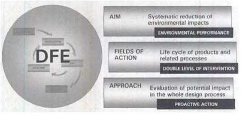
2.1.1 Objective of DFE
The objective is to minimize or eliminate, during design, the anticipated waste generation and resource consumption in all subsequent life cycle phases: construction, operation, and closure (or production, use, and disposal). In addition to its specific primary objective and its orientation toward the cycle, DFE is characterized by two other aspects as shown in figure 2.1particular:
The dual level of intervention, regarding both products and processes
The proactive action of intervention, base on the presupposition of the greater efficacy of intervening early in the product development process (i.e., in the early design phases).
Figure 2.1: Objective and characteristics of DFE
PRODUCTION
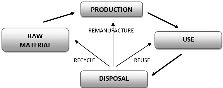
2.1.2 Approaches to optimal environment performance
The central theme unifying the various studies of DFE can be identified in the common objective of reducing the environment impact of a product over its entire life cycle, from design to disposal (Coulter et al., 1995). The concept of “reduction of environment impact” is not, however, limited to the simple quantification and minimization of direct impact on the ecosystem. Rather, in this context it has to be understood in wider terms, as the optimization of environment performance, which include a more articulated range of aspect:
Reduction of scrap and waste, allowing a more efficient use of resources and a decrease in the volumes of refuse, and, more generally, are reduction in the impact associated with the management of waste material.
Optimal management of material, consisting of the correct use of material on the basis of the performance require, in their recovery at the end of the product‟s life and in the reduction of toxic or polluting material.
Optimization of the production processes, consisting of planning of processes that are energetically efficient and result in limited emissions.
Improvement of the product, with particular regard to its behavior during the phase of use, to reduce the consumption of resources or the need for additional recourses during its operation.
Figure 2.2: Main phases of product life cycle and flow of recourses