UNIVERSITI TEKNIKAL MALAYSIA MELAKA
PROJECT REPORT
FINAL YEAR PROJECT 2
BEKU 4894
INTEGRATED OCEAN OBSERVATION SYSTEM (IOOS) FOR UNDERWATER STATION
MUHAMMAD NAQIUDDIN BIN AHMAD ZAKI
SUPERVISOR’S DECLARATION
“I hereby declare that I have read through this report entitle “Integrated Ocean Observation System (IOOS) for Underwater Station” and found that it has comply the partial fulfilment for awarding the Degree of Bachelor of Mechatronics Engineering”
Signature : ………...
Supervisor’s Name : ...
INTEGRATED OCEAN OBSERVATION SYSTEM (IOOS) FOR UNDERWATER STATION
MUHAMMAD NAQIUDDIN BIN AHMAD ZAKI
A report submitted in partial fulfilment of the requirements for Bachelor of Mechatronics Engineering
Faculty of Electrical Engineering
UNIVERSITI TEKNIKAL MALAYSIA MELAKA
STUDENT’S DECLARATION
I declare that this report entitle “Integrated Ocean Observation System (IOOS) for Underwater Station” is the result of my own research except as cited in the references. The report has not been accepted for any degree and is not concurrently submitted in candidature of any other degree.
Signature : ...
Name : ...
ACKNOWLEDGEMENT
ABSTRACT
ABSTRAK
2.7 Comparison between Current IOOS Buoy
3.9 Experimental Implementation
3.9.1 Experiment 1: Buoyancy of IOOS Buoy
4 RESULT AND ANALYSIS
4.1 Introduction 33
LIST OF TABLES
TABLE TITLE PAGE
Table 2.1 Comparison between Current IOOS Buoy 9
Table 3.1 Table 3.2
Table 3.3
Gantt chart for first semester Gantt chart for second semester IOOS Buoy
18 18 19
Table 3.4 List of Sensor on IOOS buoy 21
Table 3.5 Comparison between Thermistor and Other Sensors 24
Table 4.1 Model Information (Electronic Housing) 34
Table 4.2
Table 4.4 Mesh Information 36
Table 4.5
LIST OF FIGURES
Buoyance force of the ship (a)
Weight of ship is equal to water displaced of the ship (b)
5
Figure 3.4 Difference Size of Buoy 20
Figure 3.5 Parts in Buoy 21
Forces that work on buoy
Effect of wind and current forces to buoy
23
Payload again submerged depth of buoy Buoy condition at initial condition Water level at zero payload
Condition of buoy at maximum payload Buoy water level at maximum payload Graph for waterproof test result
Buoy condition from rear view Buoy condition from front view Center of gravity of the buoy Center of buoyancy of the buoy
CHAPTER 1
INTRODUCTION
1.1Introduction
This chapter is about an introduction of this project. This chapter will covers briefly about the research background, motivation, problem statement and objectives. The project scopes of work are determined and explained in detail. The report outline is executed.
Today, buoys are used for many purposes besides aids to navigation, including use as platform for scientific or engineering investigations, for gathering synoptic data, and supporting ocean operations such as oil tanker loading/unloading at production sites. There are strong supported from the institution for a sustained Integrated Ocean Observation System (IOOS) buoy to optimize use of existing resources and facilitate new technologies to deal with a variety of knowledge and application desires. Therefore, IOOS buoy can increase capability to satisfy challenges associated to predict the change of weather and its effects on coastal communities, marine operations, marine ecosystems, and sustained use of marine resources. Based on the Oxford Dictionary, buoy is outlined as navigation aids with floating objects, mounted to the lowest of the ocean or stream, that indicates reefs or different hazards, or for mooring. Each types of buoy have their own specifications, with different size, colour, shape and function.
several decades by providing us with significant amount of oceanographic data. However, there is still plenty of room for improving for increasing the efficiency of the system. Existing monitoring and observation systems are passive systems, whereby periodic data collections are required for further processing and interpretations. Passive observations system is exposed to several conceptual and technical disadvantages.
1.2Motivation
This project is conducted at the Universiti Teknikal Malaysia Melaka (UTeM). The reason for conducting this research work is to Integrated Ocean Observing System (IOOS) buoy for underwater station. This buoy is very important because its work as a platform for underwater station. This platform and underwater station will connected each other through wire. Buoy can generated 12V electricity from solar panel or batteries and supply it to the station. It also gives information about weather condition such as wind speed, wind direction, surrounding temperature and rainfall.
1.3Problem Statement
1.4Objectives
The objectives of this project are:
a) To design and develop Integrated Ocean Observation System (IOOS) buoy for
underwater station that can withstand high current environment. b) To sample meteorological data from the weather station for the buoy.
1.5Scope of Works
There are some scopes was outlined to achieve the stated objectives of the project.
1. To fabricate the buoy based on the design in SolidWorks.
2. To test the buoy from the point of the forces and equilibrium, and buoyancy Archimedes’ principle and buoyancy force equation by immersed the buoy into water tank.
CHAPTER 2
LITERATURE REVIEW
2.1 Introduction
In this chapter, there are elaboration about the literature review from journals that I had study about buoy system based on some criteria that are design, controller algorithm, and performance.
2.2 Design
environment including wind, current and wave drag. The positive stability will assure the buoy will not capsize due to the environmental loads or during routine maintenance operations. This may be accomplished by the proper location of weights, counterweights and by the design of the buoy geometry itself.
In conclusion, based on Figure 2.1, most buoys will have round shape for it based. This is because that shape will make less resistance to the waves. The lower part of buoy body is designed for high waves so that it can reduce the wave pressure. It is assumed a solid structure in consideration of use in case of the high wave condition. Other than that, the size of buoy depends on the component that will equip on it and the total weight of these components. The buoy should support its own payload neither normal condition nor extreme environment to carry out its duty as an IOOS buoy.
2.4 System Performance
Based on paper John C. Daidola, 1990 [14], it describes recent attempts to analyse the dynamics of typical buoys moored with synthetic line in shallow water, using an existing numerical model. Large-scale model wave tank tests have shown that the weight and drag of the synthetic line are negligible when compared to the tension forces. This allows the use of a single linear segment in the modelling of the mooring line. The procedure for extracting buoy hydrodynamic coefficients from wave tank data is outlined, along with the current capabilities of the numerical model to estimate mooring line tensions and buoy attitudes in various wave conditions.
Based on paper James Irish, 2006 [8], the buoy is powered by solar panel and wind energy. It can generate 60-watt electricity throughout clear, sunny days through solar panel and also wind generator can provides power throughout moderate wind. These systems can charge 24V and transfer it into 24V battery that can be used when sunlight is not sufficient like at night or in rainy day. The power from batteries will control all mechanism at the buoy. This provides power to the radio and controller to the pumps, valves, run down the most battery bank, and additionally permits diagnostic info to be measuring to shore to help within the identification and repair of the matter.
When an object is immersed in a fluid, the upward force on the bottom of an object is greater than the downward force on the top of the object. The result is a net upward force (a buoyant force) on any object in any fluid. If the buoyant force is greater than the object's weight, the object will rise to the surface and float. If the buoyant force is less than the object's weight, the object will sink. If the buoyant force equals the object's weight, the object will remain suspended at that depth. The buoyant force is always present in a fluid, whether an object floats, sinks or remains suspended [17].
The buoyant force is a result of pressure exerted by the fluid. The fluid pushes on all sides of an immersed object, but as pressure increases with depth, the push is stronger on the bottom surface of the object than in the top. The buoyant force can be calculated on an object by adding up the forces exerted on all of an object's sides.
The top surface has area A and is at depth ℎ , the pressure at that depth is:
� = ℎ �� (2.1)
Where ρ is the density of the fluid and g = 9.81 �� is the gravitational acceleration. The magnitude of the force on the top surface is:
� = � = ℎ �� (2.2)
This force points downwards. Similarly, the force on the bottom surface is:
� = � = ℎ �� (2.3)
If it is cylindrical, the net force on the object's sides is zero the forces on different parts of the surface oppose each other and cancel exactly. Thus, the net upward force on the cylinder due to the fluid is:
2.6 Archimedes Principle
Although calculating the buoyant force in this way is always possible it is often very difficult. A simpler method follows from the Archimedes principle, which states that the buoyant force exerted on a body immersed in a fluid is equal to the weight of the fluid the body displaces. In other words, to calculate the buoyant force on an object we assume that the submersed part of the object is made of water and then calculate the weight of that water.
Figure 2.2: Buoyance force of the ship (a) [17]
�� = ��� (2.5)
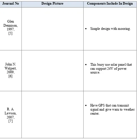
2.7Comparison between Current IOOS Buoy
Table 2.1 show the comparison between design of current IOOS buoy and the different between
components that install on each design.
Table 2.1: Comparison between Current IOOS buoy
Journal No Design Picture Components Include In Design
Glen Dennison,
1997,
[5]
Simple design with mooring.
John N. Walpert,
2009, [6]
This buoy use solar panel that
can support 24V of power source.
R. A. Lawson,
2007, [7]
Have GPS that can transmit
Stanley J. Boduch,
2006, [8]
This buoy is equip with sensor
such as wind speed, air humidity, wind direction and wave high to sample of oceanographic and meteorological data..
Marshall D. Earle, 2000,
[9]
This design is using spherical shape make it have less resistance to ocean wave and wind.
2.8Summary