UNIVERSITI TEKNIKAL MALAYSIA MELAKA
OPTIMIZATION OF WIRELESS CHARGING SYSTEM BASED
ON INDUCTION MECHANISM
This report submitted in accordance with requirement of the Universiti Teknikal Malaysia Melaka (UTeM) for the Bachelor’s Degree in Electronics Engineering
Technology (Telecommunications) (Hons.)
by
SHAFARINA WATI BINTI ISMAIL
B071110040
921223115080
UNIVERSITI TEKNIKAL MALAYSIA MELAKA
BORANG PENGESAHAN STATUS LAPORAN PROJEK SARJANA MUDA
TAJUK: OPTIMIZATION OF WIRELESS CHARGING SYSTEM BASED ON INDUCTION MECHANISM
SESI PENGAJIAN: 2014/15 Semester 2
Saya Shafarina Wati binti Ismail
mengaku membenarkan Laporan PSM ini disimpan di Perpustakaan Universiti Teknikal Malaysia Melaka (UTeM) dengan syarat-syarat kegunaan seperti berikut:
1. Laporan PSM adalah hak milik Universiti Teknikal Malaysia Melaka dan penulis. 2. Perpustakaan Universiti Teknikal Malaysia Melaka dibenarkan membuat salinan
untuk tujuan pengajian sahaja dengan izin penulis.
3. Perpustakaan dibenarkan membuat salinan laporan PSM ini sebagai bahan pertukaran antara institusi pengajian tinggi.
DECLARATION
I hereby, declared this report entitled “Optimization of Wireless Charging System Based on Induction Mechanism” is the results of my own research except as cited in references.
Signature : ……….
Author’s Name : SHAFARINA WATI BINTI ISMAIL
APPROVAL
This report is submitted to the Faculty of Engineering Technology of UTeM as a partial fulfillment of the requirements for the degree of the Bachelor’s Degree in Electronics Engineering Technology (Telecommunications) (Hons.). The member of the supervisory is as follow:
………
i
ABSTRAK
ii
ABSTRACT
iii
DEDICATION
iv
ACKNOWLEDGEMENT
I would like to take the opportunity to recognize several people who had a considerable influence on my ability to complete this report and project. First at all, I would like to thank God the Almighty who created everything and giving me the ability to start and complete this project.
I would also like to take this opportunity to thank all the people who had assisted me directly and indirectly in completing the project. I wish to express my sincere appreciation to my supervisor, Mr. Mohd Fauzi bin Ab Rahman for his guidance, advices and encouragement. Without his help and support, this project and report would not have been the same as presented here. With his helps, I had learned many things regarding the project, as well as extra knowledge that I believe I would not have this sort of opportunity elsewhere. The project would obviously not be successful without him. A million thanks to Mr. Mohd Fauzi bin Ab Rahman.
v
2.6 Current Researches on Inductive Wireless Charging 12
2.7 The Advantages of Inductive Wireless Charger 14
vi
3.6.2 Working Principle of Diode Bridge Rectifier 23
3.7 Voltage Regulator IC 24
3.8 Circuit Design 25
3.8.1 Transmitter Circuit 25
3.8.2 Receiver Circuit 25
3.9 Block Diagram of Wireless Charging System 26
3.10 Conclusion 27
CHAPTER 4: RESULT AND DISCUSSION
4.1 Introduction 29
4.2 Design and Implementation of Project 29
4.2.1 Transmitter Module 29
4.2.2 Receiver Module 30
4.2.3 Experimental Setup 31
4.3 Result and Data Analysis 32
4.3.1 Distance versus Output Voltage 32
4.3.2 Transfer Efficiency between Transmitter and Receiver 34 4.3.3 Transfer Efficiency between Transmitter and Receiver 36
4.4 Discussion 38
vii
CHAPTER 5: CONCLUSION AND RECOMMENDATION
5.1 Conclusion 40
5.2 Future Recommendation 41
REFERENCES 42
APPENDICES
viii
LIST OF TABLES
ix
LIST OF FIGURES
1.1 K- Chart 4
2.1 Electrostatic CPT System 9
2.2 System block diagram of ICPT 10
2.3 Components of inductive power transfer 11
2.4 Basic Transformer 13
2.5 Typical arrangement of a wireless inductive power transmission system
14
2.6 Dell Latitude laptop with wireless charger 16
3.1 Project planning flowchart 18
3.2 DC power supply circuit 19
3.3 Single layer air coil 20
3.4 Simple LC tank 21
3.5 Modified Royer Oscillator 22
3.6 Bridge rectifier 23
3.7 Positive half cyle (left) and Negative half cycle (right) 24
3.8 LM7805 pinout diagram 24
3.9 The transmitter circuit 25
3.10 The receiver circuit 26
3.11 Block diagram of how wireless charger works 27
4.1 Transmitter module 30
4.2 Receiver module 31
4.3 Experimental setup and collect data 32
4.4 Graph of distance vs output voltage 33
4.5 Graph of Distance vs Energy Transfer Efficiency 35 4.6 Waveform at the inductive coupling transmitter 36
x
4.8 Experiment tested using a piece of paper 37
4.9 Experiment tested using a book 37
4.10 Experiment tested using a hand 38
4.11 Experiment tested using a phone casing 38
xi IPT - Inductive Power transfer
1
1.1 Background
For more than a century now, we are using electricity and for all these years, the electricity is transmitted through wire cables to commercial and home units. We also use various electronic gadgets which uses electricity through wire cables. However, after such development of research on power transmission, it is revealed to be possible through wireless transmission of electricity. In 1831, Michael Faraday discovered induction and stated that electromagnetic forces can travel through space. The first concept that electricity can be transmitted without wire was demonstrated by Nikola Tesla in 1893 during which he demonstrated the wireless illumination of phosphorescent lamps at world exposition in Chicago. Induction is the prime principle used to transmit electricity for shorter distances. Other means like RF energy is used for short range electricity transmission. The short range electricity transmission can be used to light electric gadgets and also to charge batteries wirelessly. The main advantage of this wireless transmission technique is that we can totally do away with wires which will help us to bring the electricity to nook and corner of the world. Efficiency is the main criteria for this technology. RF energy transmission is having the least efficiency ratio while induction charger is having the most efficiency.
2 The design of wireless inductive charger is the production of electricity across a conductor situated in a changing magnetic field moving or a conductor moving through a changing magnetic field. When a conductor is subjected through a changing magnetic field, a current is induced in the conductor and this current can be stored or used. The transfer of energy takes place by electromagnetic coupling through process known as mutual induction. This process works only in short distances and can be used to run electric gadgets.
1.2 Problem Statement
Today, almost each and everything are wireless or cordless. And these have definitely increased the standard of living. With many users owning more than one handheld device, the resulting collection of bulky chargers is inconvenient to use. In this project, inductive charging will ensure that the cell phones, laptops, iPods and other power hungry devices get charged on their own, eliminating the need of plugging them in. Even better, because of inductive charging some of the devices won't require batteries to operate. Tangles of wires and bulky chargers are no longer required. Inductive charging carries a far lower risk of electrical shock, when compared with conductive charging, because there are no exposed conductors.
Wireless power just about freedom from power cords and convenience; it also changes the way manufacturers can design devices. Eliminating the power socket is a
major step toward a sealed and even thinner smartphone that’s waterproof and
dustproof. Such a device would at the same time be more reliable and rugged, and it would not need a flat edge to mount the power socket on. The availability of wireless charging everywhere would further allow designers to consider smaller batteries because users would be able to simply top up their battery charge as needed.
3 devices with different sizes and shapes. Also, the wireless chargers provide power to battery with lower efficiency compared by using the wires chargers.
1.3 Project Objectives
The objectives of this project are to:
(i) Investigate the near field wireless power transfer application. The investigation consists of the comparison between a few methods in transferring power wirelessly over short distance. The inductive power transfer via inductive coupling will be proposed as the most efficient method in this investigation. (ii) Design a wireless power system to transmit voltage wirelessly from the source to
device. The wireless battery charger for electronic gadgets is designed based on induction charging technique consists of transmitter and receiver.
(iii)Test and evaluate the wireless charging performance in transmitting the power to battery. Measurements such as output voltage, energy transfer efficiency, and wave forms will be analyzed.
1.4 Project Scopes
4 Figure 1.1: K-chart
5 limiting the capability of this wireless charger to transfer 5W at a maximum distance of 2.5 cm, which is sufficient to charge a regular mobile phone.
1.5 Project Significance
Nowadays, the portable electronic devices are very popular. Hence, as the usage of these portable electronic devices is increasing, so does the demands to have longer
battery life which are also increasing. Periodically, these device’s batteries need to be
recharged or replaced. It is inconvenient to change or charge the battery especially when without the presence of any power outlet around users. Therefore, the wireless
battery charger is expected to eliminate all the difficulties with today’s battery
technology. For the handheld device users, it create such convenience as they do not have to worry about charging their devices and still have a working device. This project should help to wirelessly charge up the batteries which can save time and money in a long run for the general public.
1.6 Thesis outline
There are all five chapters being structures in this thesis and every chapter will elaborate in detail about this project. Chapter one states the overview and introduction of the project which inclusive of project background, project objectives, problem statement, project significance and scope of work.
6 Chapter three discusses the methodology that I use to transmit the energy wirelessly. In this chapter it will be presented using the three stages in flow chart. It will describes the methods and technique selected for implementation in this project.
Chapter four is analyses and displaying all the results obtained and the limitation of the project. All analyses are concentrated on the result and the overall performance of the wireless power transfer. From the result, the analysis was do to see the project is function properly. All the simulation, data collection and analysis that were obtained from the project will be discussed in detail. The result was compared with the outlined objectives in order to state the hypothesis and conclusion of the project.
Chapter five concludes the whole research work and states recommendation for the future research work. In this chapter, conclusions are made on achieving the objective of the project.
1.7 Conclusion
7
2.1 Introduction
The development of charging system that have the capability of wireless power transfer is a recent trend in designing the power supply. In other words, the power supply will not be plugged into the charging device. For a long time, the technology of wireless power transfer have existed, but the recent development and interest of market have allowed it to be more practical, and hence brought to the center of attention, (A. Kurs, 2007).
This chapter will explain and discuss about the literature review on wireless power transmission that have been in research before. These studies and researches will be used as the reference in this project development. This review will focus on the near field wireless power transfer, electromagnetic induction, inductive coupling, magnetic field, wireless charger and its advantages.
2.2 Wireless Power Transfer Systems
Wireless Power Transfer is defined as an efficient transmission of electric power from one point to another through vacuum or an atmosphere without the use of wire or any other substance, (Yusop, et al., 2012). The history of wireless power
8 transmission can be traced back to the late of 19th century, which Maxwell predicted
in his “Tretise on Electricity and Magnetism” that power could be transmitted from
one point to another in free space. While Heinrich Rudolf Hetrz experimenting based
on Maxwell’s equation which was a monumental step towards the direction. Nikola
Tesla also performed the experiments that are consideres as the most serious demonstrations in showing the capability of wireless power transmission eventhough his attempts to send power to space failed, (Prasanth, 2011).
The wireless transmission is beneficial where interconnected wires are inconvinient, hazardous or impossible. For users with disabilities, wireless charging is a suitable option since instead of connecting power cable to device, it can be placed on the charging plate. The user can keep a track on the charging amount on the devices in order to avoid overcharging or overheating. The increasing number of portable devices for example tablets, cell phones, etc. provide inconvinience to seperately charge all of them and had to carry number of chargers everywhere the user go. Hence the wireless charging provides ideal solution for this problems, (Supe, et al., 2014).
2.3 Electromagnetic Induction
Electromagnetic Inductive Power Transfer (IPT) is a popular method to transfer power wirelessly over a short distance. There are two fundamental laws of physics
used in this technique which are Faraday’s Law and Ampere’s Law, (Prasanth, 2011).
In inductive power transfer system, the process is where electrical power is transmitted wirelesslyfrom source to an object that requires power. The pros of using inductive power transfer is it eliminates the inconvinient and hazardous wires and cables, (Dunne, 2009).
9 1. Electrostatic Induction
2. Electrodynamic Induction
2.3.1 Electrostatic Induction
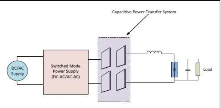
Electrostatic Induction or Capacitive power transfer (CPT) is a method to wirelessly transfer power between two electrodes of capacitor assembly. Electric field are formed and displacement current maintains its continuity, when high frequency source ac voltage is supplied to the plates of capacitor that are placed close to each other. Hence, in this technique, the electric field is the energy carrier media, thus it is the dual of IPT, (Prasanth, 2011).
Figure 2.1: Electrostatic CPT system
2.3.2 Electrodynamic Induction