IN HUB OF SWITCH RELUCTANCE MOTOR DESIGN FOR ARM JOINT
NOOR IDAYU BINTI AHMAD
A report submitted in partial fulfillment of the requirements for the degree of Bachelor of Electrical Engineering (Power Electronic and Drive)
Faculty of Electrical Engineering
UNIVERSITI TEKNIKAL MALAYSIA MELAKA
“I hereby acknowledge that I have read this project report entitle “In Hub Switch Reluctance Motor Design For Arm Joint” and found that it has comply the partial fulfillment for awarding
the degree of the Bachelor of Electrical Engineering (Power Electronic and Drive)”
Signature : ……….
Supervisor’s Name : Dr. Kasrul B. Abdul Karim
i
IN HUB OF SWITCH RELUCTANCE MOTOR DESIGN FOR ARM JOINT
NOOR IDAYU BINTI AHMAD
This project report is proposed as to fulfill a fraction Of the regulations of presentation of the Bachelor of Electrical Engineering with Honors
(Power Electronic and Drive)
Faculty of Electrical Engineering
UNIVERSITI TEKNIKAL MALAYSIA MELAKA
”I hereby declare that this report entitle “In Hub of Switch Reluctance Motor Design for Arm Joint”is the result of my own research except as cited in the reference. The report has not been
accepted for any degree and is not concurrently submitted in candidature of any other degree“
Signature : ……….
Student’s Name : Noor Idayu Bt Ahmad
iii
Special for my beloved parent Ahmad bin Saman
Puteh Mahani bt Asha @ Md Isa
Thank you for your continuous support, understanding and advices
My beloved sister Suraya Ahmad Suzana Ahmad Junainah Ahmad Siti juriah Ahmad Thank you for your support
For my best friend and others Nor Mazura Bt Shahrin Wan Nazlin Bt Wan Abdullah
Nurul Atiqah Bt Ismail
Aisyah Bt Aziz Nurul Husna Bt Tajudin
Who was always by my side when I need them for support and advices, I really appreciate what they have done. Thanks guys.
ACKNOWLEDGEMENT
In the name of Allah, the Most Gracious and the Most Merciful
Alhamdulillah, all praises to Allah for the strengths and His blessing in completing this final year project.
First of all, I would like to express my gratitude and appreciation to all those who gave me the possibility to complete this report. Special appreciation goes to my supervisor, Dr. Kasrul Bin Abdul Karim, for his supervision and constant support. His invaluable help of constructive comments and suggestions throughout the experimental works have contributed to the success of this project.
My Thanks you for my friend, who helps me to assemble the parts and suggestions and encouragement, helped me to coordinate my project.
v
ABSTRACT
ABSTRAK
vii
TABLE OF CONTENTS
CHAPTER TITLE PAGE
THESIS STATUS DECLARATION FORM SUPERVISOR’S DECLARATION
TITLE OF PROJECT REPORT i
DECLARATION ii
DEDICATION iii
ACKNOWLEDGEMENT iv
ABSTRACT v
ABSTRAK vi
TABLE OF CONTENTS vii
LIST OF TABLES xi
LIST OF FIGURES xii
LIST OF ABBREVIATIONS AND SYMBOLS xiv
LIST OF APPENDICES xv
CHAPTER 1 INTRODUCTION
1.1 Project Overview 1
1.2 Problem Statement 3
1.3 Project Objectives 4
1.4 Scope of Project 4
CHAPTER 2 LITERATURE REVIEW
computation from finite element field
solution 6
2.1.2 Design and Optimization of High Torque, Low Ripple Switched Reluctance Motor
with Flux Barrier for Direct Drive 6 2.1.3 A Simplified Design Methodology for
Switched Reluctance Motor using
Analytical and Finite Element Method 7 2.1.4 Simulation research on Switched
Reluctance Motor Modeling and Control
Strategy based on ANSOFT 7
2.2 Summary of Case Study 8
2.3 Theories 10
2.3.1 Background 10
2.3.2 Switch Reluctance Motor Configuration 11 2.3.3 Switch Reluctance Motor Basic Operation 12
2.3.4 Dimensional Design 13
CHAPTER 3 METHODOLOGY
3.1 Introduction 16
3.2 Finite Element 17
3.2.1 Process flow chart of FEA 18
3.3 Motor design 19
3.3.1 Parameters 19
3.4 Simulation process 22
3.5 Analysis setup 23
3.6 Variable of core length 23
ix
3.9 Variable of yoke thickness 25
3.9.1 Analysis process 26
CHAPTER 4 RESULTS
4.1 Introduction 28
4.2 Simulation result 28
4.3 Result of the performance of SRM (RMXprt) 29 4.3.1 Input DC current VS speed 30
4.3.2 Efficiency VS speed 30
4.3.3 Output power VS speed 31 4.3.4 Output torque VS Speed 31 4.3.5 Maximum phase current 32
4.3.6 Rated phase current 32
4.3.7 Flux linkage 33
4.3.8 Air gap inductance 33
4.3.9 Phase voltage 34
4.4 Result of the performance of SRM (2D design) 35
4.4.1 Torque 35
4.4.2 three phase winding current 35
CHAPTER 5 ANALYSIS AND DISCUSSION
5.1 Introduction 36
5.2 Variable parameter for SRM design 36 5.2.1The variable of core length 37 5.2.2 The variable of embrace 38 5.2.3The variable of turn per pole of stator
winding 42
5.2.4 The variable of yoke thickness 44
CHAPTER 6 CONCLUSION AND RECOMMENDATION
6.1 Conclusion 47
6.2 Recommendation 48
REFERENCES 49
xi
LIST OF TABLES
TABLE TITLE PAGE
2.1 Specification of case study 8
2.2 Summary of case study 9
2.3 Condition of the number of pole of rotor and slot of stator
15
2.4 Condition of the number of pole rotor and slot of
stator 15
3.1 Desired SRM design for arm joint 26 5.1 The output torque and efficiency with different
value of core length 37
5.2 The output torque and efficiency with different
value of embrace stator 39
5.3 The output torque and efficiency with different
value of embrace rotor 40
5.4 The output torque and efficiency with different
value of the turn per pole 42
5.5 The output torque and efficiency with different
value of yoke thickness 46
LIST OF FIGURES
FIGURE TITLE PAGE
1.1 Application motor for Robotic Arm System 2
2.1 Classification of SRM 11
2.2 Cross section of switch reluctance motor 12 2.3 Operation of switched reluctance motor 13
3.1 The flow of the process 16
3.2 Machine data 19
3.3 Circuit data 20
3.4 Stator data 20
3.5 Winding at stator data 21
3.6 Rotor data 21
3.7 Error condition 22
3.8 Analysis setup data 23
3.9 Length of the motor 24
3.10 Embrace of the motor 24
3.11 Winding of the motor 25
3.12 Yoke thickness of the motor 25
3.13 The work flows of the simulation process 27 4.1 (a) switch reluctance motor in normal design (RMXprt) .
(b) Switch reluctance motor in 2D design 29
4.2 Input DC Current vs Speed result 30
4.3 Efficiency vs Speed 30
4.4 Output Power vs Speed 31
xiii
4.7 Rated Phase Current 32
4.8 Flux linkage 33
4.9 Air Gap Inductance 33
4.10 Phase Voltage 34
4.11 Output torque waveform 35
4.12 Phase winding current waveform 35
5.1 Graph output torque and efficiency VS length of motor 38 5.2 Graph output torque and efficiency VS embrace of the
stator 39
5.3 Graph output torque and efficiency VS embrace of the
rotor 40
5.4 (a) The embrace stator of SRM design (b) The embrace
rotor of SRM design 41
5.5 Graph output torque and efficiency VS turn per pole of
stator winding 43
5.6 Graph output torque and efficiency VS yoke thickness of
the motor. 45
LIST OF ABBREVIATIONS AND SYMBOLS
к - constant
τ - torque
Φ - flux
I - Current
L - Inductance
ɵ - Position of inductance in degree.
Pout - Output power
Pin - Input power
ɳ - efficiency
CVW - Coulomb Virtual Work MST - Maxwell Stress Tensor Nr - Total number pole of rotor
Ns - Total number slot of stator �� - Pole angle of the stator
�� - Pole angle of the rotor
xv
LIST OF APPENDICES
APPENDIX TITLE PAGE
A Project Planning for PSM I 53
B Project Planning for PSM II 54
CHAPTER 1
INTRODUCTION
1.1 Project Overview
2
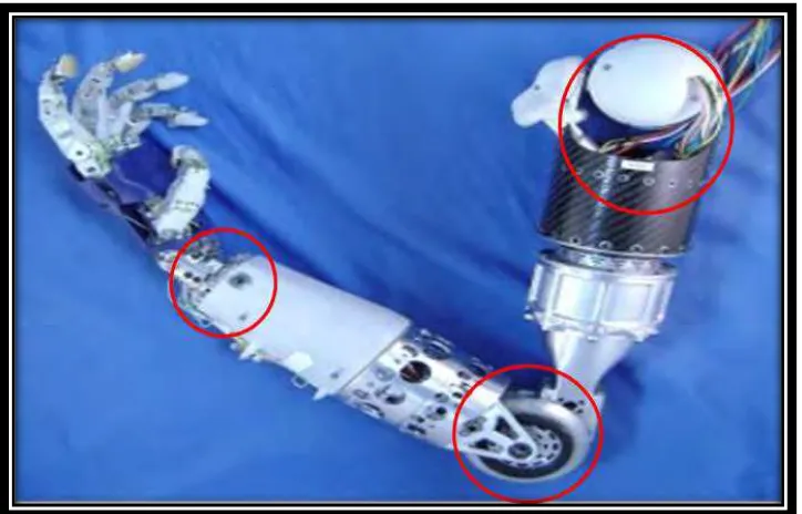
Figure 1.1: Application motor for Robotic Arm System
Nowadays, machine usage is very widespread and some critical part of the machine components needs a motor to facilitate movement. In constructing a robot, arm joint is the important areas in movement and one of the components to supplement arm joint perfectly is motor. Commonly, Brushless DC motor is used, however this type of motor is relatively expensive because this motor use permanent magnet and have complex controller.
4
1.3 Project Objectives
The major objective of this project is designing a Switched reluctance motor. Its measurable objectives are as follow:
i. To design and develop basic configuration of Switched reluctance motor.
ii. To determine the parameter depend on variable consideration such as length, embrace, yoke thickness and turn per pole.
iii. To analyze the performance characteristics of the switch reluctance motor using finite element analysis (FEA).
1.4 Scope of Project
This project is primarily concerned with the Switched reluctance motor technologies. The scopes of this project are:
i. Analysis the SR Motor using finite element analysis (FEA).
ii. Determine the performance of switch reluctance motor. (100 Nm – 50 Nm and small size).
CHAPTER 2
LITERATURE REVIEW
2.1 Technology Development
6
2.1.1 Switch reluctance motor torque computation from finite element field solution
This project was designed by A. Benhama, A. C. Williamson, and A.B.J. Reece fromUniversity of Manchester Institute of Science and Technology (UMIST) (1997).
This project discusses basic analysis method switch reluctance motor in order to correct the deficiency and shows that the CVW method can be superior in accuracy and implementation to the MST method [1]. The paper has reviewed existing methods of force and torque computation from the finite element field solutions. It has highlighted the difficulties in the application of the MST method of torque computation to 3D finite element problems, and showed that the CVW method may be superior in accuracy and implementation to the MST method. Application of the CVW method to an experimental switched reluctance motor demonstrated this accuracy. As a result, accounted from CVW 3D stay deep agreement that is very good with data measured, only 4% difference that exists [1]. The FE 3D analysis and method CVW 3D eliminates fully error introduced by effect.
2.1.2 Design and Optimization of High Torque, Low Ripple Switched Reluctance Motor with Flux Barrier for Direct Drive
Analytical and Finite Element Method
This project was designed by M.H.Ravichandran, V.T.Sadasivan Achari, C.C.Joseph and Robert Devasahayam. In This paper gives the step-by-step design procedure of a 16/12 Switched Reluctance Motor for a spacecraft actuator. Machine design has been started with analytical method to fix the major parameters and optimization is carried out using Finite element technique [3]. The Basic design has been started with Analytical method to fix up the major parameters and optimization of dimensions has been carried out using FE method.
2.1.4 Simulation research on Switched Reluctance Motor Modeling and Control Strategy based on ANSOFT