ii Declaration
“I hereby declare that all information provided in this report is true and is my own work except for the details that I already explained from whom/where it is taken from”
Student Signature :
Student’s Name : Neilson Peter David Sorimpuk
iii ACKNOWLEDGEMENT
iv ABSTRACT
v TABLE OF CONTENT
CHAPTER CONTENT PAGE
DECLARATION i
ACKNOWLEDGEMENT ii
ABSTRACT iii
TABLE OF CONTENT iv
NOMENCLATURE v
LIST OF TABLE ix
LIST OF FIGURE x
LIST OF APPENDIX xi
1.0 INTRODUCTION 1
1.2 1.3 1.4 Problems Statement Objectives Scope Specification 1 1 1 2
2.0 LITERATURE REVIEW 2
2.1 2.2 2.2.1 2.2.2 2.2.3 2.2.4 2.3 Background studies.
Parts and Components Studies Ignition Key
Starter Motor Relay
Micro-Controller Unit Previous Invention Studies.
vi 2.4 2.5 Alternative Solution 13 14
3.0 METHODOLOGY 15
4.0 PRELIMINARY DESIGN 18
4.1 Design Concept 18
4.2.1 Part A- Before Modification 19
4.2.2 Part B- After Modification 21
4.2.3 Process Sequence 22
5.0 PROJECT DEVELOPMENT 23
5.1 Circuit Development 24
5.2 System Development 25
5.3 Model Fabrication 30
6.0 PARTS AND COST ESTIMATION 32
7.0 PROJECT EVALUATIONS 34
8.0 DISCUSSION 35
8.1 Circuit analysis 35
8.2 System analysis 38
8.3 Safety Issues 39
8.4 Software and Programming Development 40
8.4.1 Programming Software 40
8.4.2 Electronic Software 41
vii
8.6 Project Evaluation 42
8.7 Improvement and Modification 43
8.8 Ergonomics Value 44
9.0 CONCLUSION 45
10 REFERENCES 46
viii NOMENCLATURE
1. MCU = microcontroller uint
2. IC = Intergrated Circuit
3. ACC = Accessories
4. CPU = Central Processing Unit
5. BAT = Battery
6. IG = Ignition
ix LIST OF TABLES AND FIGURES
Table Title Page
1 Alternatives Comparison Table 14
2 Project Gantt Chart 17
3 Result of Manual Ignition Key Experiment 19
A Remote Control System Components 32
B Model Component 32
x LIST OF FIGURES
Figure Title Page
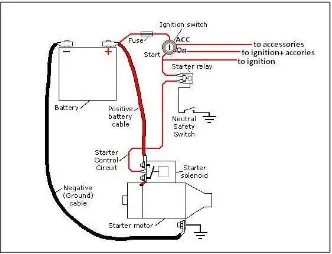
1 A Simple Starter Diagram 4
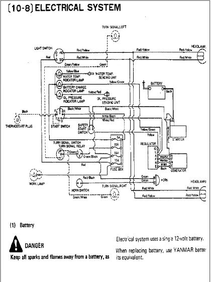
2 A Typical Mazda 323 1985 Model Starter Wiring Diagram 5
3 A simplified Conventional Starter System Diagram 6
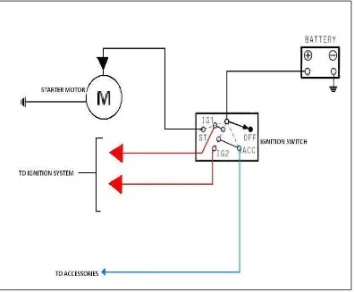
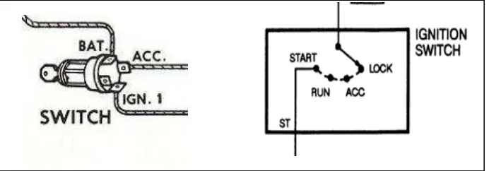
4 Ignition Switch Diagram 7
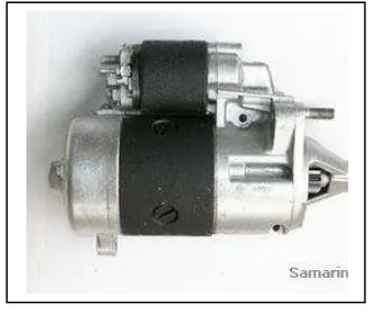
5 Starter Motor 8
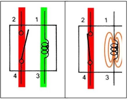
6 Relays Operation 9
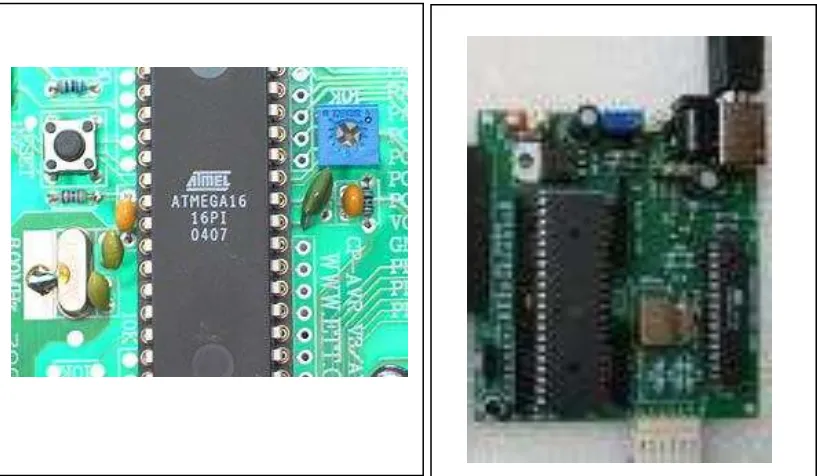
7 ATmega16 Microcontroller 10
8 Development Board 10
9 Comparison of Conventional (top) and Modified Starter Wiring Diagram (bottom).
18
10 Figures of Determining the Ignition Switch Circuit. 20
11 A Simplified Modified Starter System Diagram 21
12 Process Block Diagram 23
13 Project Schematic Diagram 24
14 Microcontroller Programming 29
15 Model Design 30
16 Aircond System 31
17 Ignition Key System 31
18 Starter Motor and Engine Configuration 31
19 Source Code Verification 34
20 Wiring Circuit Verification 35
xi
22 External Pull-Up Resistor Circuit Type B 37
23 Figure 23: PIC-GSM Development Board With Gsm Module And PIC18f67j50 Microcontroller
43
LIST OF APPENDIX
APPENDIX A: US PATENT 5129376 APPENDIX C: US PATENT 4598209
APPENDIX D: TOYOTA AND MAZDA WIRING SYSTEM APPENDIX E: CIRCUIT SCHEMATIC DRAWING
APPENDIX E1: REPORT APPROVAL
1 1.0 INTRODUCTION
1.1 Problems Statement
Vehicle left parked at open area is exposed to the surrounding temperature and sun shine thus heating the inside compartment of the car. As the car ventilation is closed during parked, the heat inside the compartment will accumulate and dissipates slowly as the air conditioner is switched on, or the side windows are rolled down. The inconveniency arises when we are picking up our car; we start the car manually then we have to sweat inside waiting the car’s air conditioner lowering the temperature.
1.2 Objectives
The objectives of this project are:
1. To study the sequence of car starter system.
2. To develop a car automatic starting system using a remote control.
3. The system developed should able to activate the air conditioner automatically.
1.3 Scope
a. For PSM 1:
1. Problems statements: Studying and identifying problem that arisen. 2. Specification: Determining the requirements to solve the problems.
3. Alternative: Providing options that may have the potential to solve the problem.
4. Solution: To choose the best option based on the criteria and requirement outlined.
2 b. For PSM 2:
1. Design Detail: Providing a full detail on the design including the complete wiring diagram and programming data base.
2. Fabrication: Developing or simulating the system.
3. Evaluation: Examining the system in terms of its functionality.
4. Modification: Performing any necessary improvements or adjustments.
1.4 Specification
The system developed should be: Simple
low power consumption packed in a small size
able to override the key ignition system
Can be triggered by a long range or short range signal using a remote control unit.
Time triggered
Complete with security systems which only can be triggered by the authorized personnel or the owner of the vehicle.
3 2.0 LITERATURE REVIEW.
2.1 Background studies.
Our local climate can be described as hot especially during the midday. Living with temperature within the average of 29-32 degree of Celsius a day can be considered as inconvenience by certain peoples. For this reason, we are always choosing to hide behind the shades during the day as to avoid the temperature from the sun. We build shelter to protect ourselves from the uncomfortable feeling of being exposed to the heat. Besides of living comfort in the shelter, we are also wanted to be comfortable in traveling. Air conditioners are equipped in the vehicles to do so. But, every time we are picking up our car which parked outside the shelter, we will wish that our air conditioner system is operating at double times so the heat inside the compartment will be lowered down very soon. This problem arisen as the car was exposed to the direct heat from sun, the heat will build up inside the compartment. As the ventilating system of the car is closed, the heat inside the compartment will continuously accumulating until a certain degree. So, the time taken for the car air conditioning system to lower the temperature will be much longer.
4 Figure 1: A Simple Starter Diagram
5 Figure 2: A Typical Mazda 323 1985 Model Starter Wiring Diagram
6
7 2.2 Parts and Components Studies
2.2.1 Ignition Key
The ignition switch generally has four positions: off, accessories, on, and start and some cars have five including lock position. At
the accessories position, low power consuming accessories, such as the radio, are activated; however, high power consuming accessories such as window motors remain off in order to prevent the car's battery from being drained.
The accessories position uses the least amount of battery power when the engine is not running,
The on position turns on all of the car's systems, including the fuel pump and this is the position the ignition switch remains in while the engine is running.
The start position is spring loaded so that the ignition switch will returns to the on positionwhen the key is released. When the key is released from the start position, it returns to the on position, cutting power to the starter. This is because the engine runs at speeds that the starter cannot match, meaning that the starter gear must be retracted once the engine is running on its own.
8 2.2.2 Starter Motor
The starter motor is a powerful electric motor as it is needed to spin the engine at the beginning of starting the engine. It is attached with a small gear (pinion) which will meshed with a larger gear (ring), which is attached to the engine upon activation. The starter motor then spins the engine over so that the piston can draw in a fuel/ air mixture, which is then ignited to start the engine. This is done by pushing the pistons to create a vacuum volume which will open the air intake valve and sucks the air entering the combustion chamber. After the engine is running on its own, the starter motor must be deactivated to avoid damage on its gear and components as the engine is spinning faster than the motor. However, a coupling or clutch like system is installed on the starter motor which allows the motor to detract automatically whenever the engine gear is rotating faster than the motor itself.
Usually, a starter motor is paired with a starter relay or a starter solenoid to allow the starter being activated by a low current from the ignition switch.
Figure 5: Starter Motor
9 2.2.3 Relay
Relay is an electronic switch that is controlled by electric current. Working by the principle of a solenoid, relay is often used to control the flow of a larger current to a circuit while it is actuated only with a small amount of current.
10 2.2.4 Micro-Controller Unit
The microcontroller is a single chip of Integrated Circuit (IC) which is programmable and used as a controller in a system. It is consists of several parts such as Timer, Counter, Memory, and build in circuit interface. Also known as Central Processing Unit (CPU) with reduced computing power, it is installed in a system as a controller to process any inputs from sensors or other circuit into an output to the mechanical actuators. The inputs collected by the microcontroller are processed based on the commands that are programmed by the inventor using computer programs. Able to repeat the command lines as many as it is programmed to, compact, adaptive as the programmed data can be change or modified according to the needs, and is also can perform multi tasks upon activation makes it is the most significant component that should be applied on this project.
11 2.3 Previous Invention Studies.
Several studies and development on this invention had been made since 1992. According to the US Patent 5129376 (year 1992):
a. The remote control starter is activated by a mobile phone as a sender and a pager as a receiver.
b. Since the pager will beep upon receiving a signal, the user decided to use a sound sensor as the circuit controller/switch.
c. Along with the starter unit, temperature and oil pressure monitoring unit are also installed.
d. The invention are claimed to be able to reactivate the car starter if the engine dies within a minute automatically.
e. The honk will be also activated as the indicator when the engine reached the desired temperature.
From the studies that have been made from several previous inventions, there are several critical points that should be noted on this previous invention.
a. circuit design
The circuit is consists of several relays and timers which actuated in several sequences. Studying the circuit is helping on relays and timers usage as a switch and sequence triggering.
b. process sequence
The operation begins with the sound sensor receiving input from the pager then actuates the first relay and so on until the engine is started. c. feedback systems.
12 The advantages are:
The system able to restart by itself if there is a failure on the attempt within the first minute.
The system consists of engine pressure and temperature monitoring systems which will decide how long the car will be in ignited.
The system is operated by fully electronic based components. Thus, it is more reliable and easier to be operated.
The system consists of status display (by LED) which will ease the user to operate it.
The disadvantages are:
As claimed by the inventor, the device is operated within a 75 miles radius. This is still not applicable for those who need a longer range.
The system is relies on sound sensor to interpret the signal from the user. This may leads to accidentally triggering if there is a noise penetrating through the acoustic chamber to the sensor.
Practically, the invention is out dated since it is using a pager, and also is quiet complex to be understood.
13 2.4 Alternative
Based on the problems stated and by referring the previous invention that ever made, there are few alternatives that can be applied to trigger the engine starter and has the requirement as the solution. Each of them has the advantages and disadvantages which will be compared as follows.
Alternatives Advantages Disadvantages
1. Via radio wave remote control.
Low cost Simple Easy to use Small size of
controller unit.
Short range Easily effected by
surrounding interference Least frequency
variable
Remote control unit and receiver unit are usually
manufactured as a package-lost of remote controller may results in high cost of
replacement. 2. Via Mobile Phone
(GSM wave)
Wide range and coverage
Can be applied to a specific phone number
Everyone has a mobile phone Mobile phone itself
has the alarm clock feature.
High cost
Is restricted to be turned on in the gas station area because
of its