DESIGN AND FABRICATE FOR KNUCKLE RACING ELECTRIC CAR WITH HIGH PERFORMANCE AND REALIBILITY
MUHAMAD FARHAN BIN FADZILAH HUSANI
This report is presented in
Partial fulfillment of the requirement for the
Bachelor of Mechanical Engineering ( Design and Innovation)
Faculty of Mechanical Engineering Universiti Teknikal Malaysia Melaka
i ‘I/We* have read this thesis
And from my/our* opinion this thesis
Is sufficient in aspect of scope and quality for awarding Bachelor of Mechanical Engineering (Automotive)’
Signatures : ...
Name of Supervisor I : En.Safarudin Ghazali Herawan Date : ...
Signatures : ... Name of Supervisor II : ... Date : ...
ii DECLARATION
“I declare this report is on my own work except for summary and quotes that I have mentioned its sources”
iii Especially for my father, Fadzilah Husani B Sirat and my mother,
iv ACKNOWLEDGEMENT
Considerable gratitude and many thanks goes to those who have helped making this final year project possible, as well as those who have contribute to this project or my education profile.
Special Thanks To:
En.Safarudin Gazali Herawan Dr.Muhamad Zahir B Hasan Leopard Racing Team Zahir Racing Team
Organizer of Formula Varsity 2010 Especially:
vi ABSTRAK
v ABSTRACT
vii Content
CHAPTER TITLE PAGE
PREFACE i
DEDICATION ii
ACKNOWLEDGEMENT iv
ABSTRACT v
ABSTRAK vi
TABLE OF CONTENT v
LIST OF TABLE xi
LIST OF FIGURE xii
LIST OF SYMBOLS xiv
LIST OF ABBREVIATION xv
LIST OF APPENDIX xvi
CHAPTER 1 INTRODUCTION 1
1.0 Formula Varsity 1
1.1 Objective 3
viii
1.2.1 Upright Weight 3
1.2.2 Upright Parts 4
1.3 Scopes 5
CHAPTER 2 LITERATURE REVIEW 6
2.0 Design Review 6
2.0.1 Total Design Method 6
2.0.2 Design Error 8
2.1 Material Review 11
2.1.1 Steel 11
2.1.2 Plain Carbon Steel 11
2.13 Mild Steel 11
2.14 Aluminium 12
2.2 Joining Review 12
2.3 Analysis Review 13
2.3.1 Forces Acting On Suspension 14
2.3.2 Brake Force Equation 14
CHAPTER 3 METHODOLOGY 16
3.0 Introduction 16
3.1 Project Flow Chart 16
3.2 Designing The Upright or Knuckle 18
ix 3.2.2 Product Design Specification 18
3.2.3 Conceptual Design 19
3.2.4 Detail Design 19
3.2.5 Fabrication 19
3.3 Material Selection 19
3.4 Analysis 20
3.4.1 Static Case 20
3.4.2 Lateral Force 22
3.4.3 Forces Determination 22
3.4.4 Structure Analysis 23
CHAPTER 4 RESULT AND ANALYSIS 24
4.0 Total Design Method 24
4.0.1 Market Investigation ` 24
4.0.2 Conceptual Design 26
4.0.3 Evaluation and Selection of Concept 28
4.0.4 Design Rating 30
4.1 Material Selection 31
4.1.1 Introduction` 31
4.1.1.1 Steel 31
4.1.1.2 Plain Carbon Steel 32
4.1.1.3 Mild Steel 33
4.1.1.4 Medium Carbon Steel 33
4.1.1.5 High Carbon Steel 33
4.1.1.6 Alloy Steels 34
4.1.1.7 Stainless Steel 34
4.1.1.8 Aluminium 35
4.1.2 Comparisons 36
4.1.3 Conclusion 36
4.2 Load Analysis 37
4.2.1 Static Analysis 37
x
4.3 Structure Analysis And Results 42
4.3.1 Structure Analysis 42
4.3.2 Result 44
CHAPTER 5 FABRICATION 45
5.0 Introduction 45
5.1 Fabrication Flow Chart 45
5.2 Project Planning 47
5.3 Material Purchasing 48
5.4 CAD Drawing and Dimension 48
5.5 Construction 50
5.2 Finishing 55
CHAPTER 6 DISSCUSSION 56
6.0 Upright After Fabrication Process 56
6.1 Weight Reduction 57
6.2 Component Reduce 58
6.2.1 Major Component 58
6.2.2 Subpart Reduction 58
CHAPTER 7 CONCLUSION AND RECOMMENDATION 60
7.0 Conclusions 60
7.1 Recommendation 61
7.1.1 Design Recommendation 61
7.1.2 Analysis Recommendation 61
7.1.3 Material Selection Recommendation 61
REFFERENCES 62
xi LIST OF TABLES
TABLE TITLE PAGE
4.1 Weighting Factor 29
4.2 Rating for Each Upright/knuckle 30
xii LIST OF FIGURES
FIGURE TITLE PAGE
1.1 Suspension Assembly 2
1.2 Quarter Car Suspension Model 3
1.3 Current Upright Design 5
2.1 Design Core 7
2.2 Failed Upright 8
2.3 FSAE Team Upright 8
2.4 Unreliable Design 9
2.5 Analyzed Upright Design 10
2.6 Sample Calculation 14
3.1 Process Flow Chart 17
3.2 Static Loads On Level Ground 20
3.3 Use Of Electronic Scale 21
3.4 Free Body Diagram of Rear Suspension 22
4.1 F1 Upright 25
4.2 F1 Upright 25
4.3 Example Of Formula Student Uprights 25
4.4 Example of RC upright 25
4.5 Upright 1 26
4.6 Design Concept of Upright 1 26
4.7 Upright 2 27
4.8 Upright 3 27
4.9 Concept Generation Of Upright 1 28
4.10 Steel 32
4.11 Tensile Strength and Hardness of Plain Carbon 32
4.12 Stainless Steel 34
xiii
4.14 Rectangular Roughness Conering 37
4.15 Front Suspension Free Body Diagram 38
4.16 Relations Between Master Pump And Caliper Piston 40
4.17 Forces Distribution on Upright 42
4.18 Torque Applied On the Caliper Mounting 42
4.19 Load Distribution 43
4.20 Displacement Of The Upright 43
5.1 Fabrication Flow Chart 46
5.2 The Breakdown Structure of Upright/Knuckle 47
5.3 Solid Steel and Hollow Square Steel 48
5.4 Detail Drawing and Dimension 49
5.5 Bend Saw 50
5.6 Conventional Lathe 50
5.7 Cutting Tool 1 51
5.8 Cutting Tool 2 51
5.9 Cutting Tool 3 51
5.10 Cutting Tool 4 52
5.11 Housing Bearing 52
5.12 Hollow Square Steel 53
5.13 Disc Cutter 53
5.14 Housing Bearing Jig 53
5.15 Curved End of Shape 54
5.16 Complete Area 2 54
5.17 Upper Mounting 54
5.18 Lower Mounting 54
5.19 Complete set 3 55
5.20 Final Desaign After Finishing Process 55
6.1 Weighting Both Upright/Knuckle 57
6.2 Caliper Mounts 58
6.5 Location of Subparts reduce 58
xiv LIST OF SYMBOLS
Θ1= angle (degree) Θ2= angle (degree) Θ3= angle (degree) Σ = Sigma
Π= 3.45
xv LIST OF ABBREVATION
RC= Remote Control F1= Formula One
FSAE= Formula Society Automotive Engineering CNC = Computer Numerical Control
xvi LIST OF APPENDIX
NO TITLE PAGE
A Technical Drawing 66
B Flow Chart And Gantt Chart 70
C Regulation Of UteM’s Formula Varsity 73
1 CHAPTER 1
INTRODUCTION
1.0 FORMULA VARSITY
Universiti Teknikal Malaysia Melaka (UTeM) Formula Varsity is an
international student racing competition that challenges students to
design, manufacture and race their single seat open-wheel formula style racing car in
real track condition. This event is inspired by similar student racing event such as
formula student and formula SAE. The events have provided a platform for
Malaysian student to practice their knowledge in engineering through motorsport
event. The event hope to foster the tie and collaboration between all Malaysian and
2 to help create the needed competent human capitals for our country automotive
industries.[20]
The UTeM formula Varsity 2010 team consists of 11 member crews that are
appointed for the car fabrication. After completion, several problems were founded
that affected the performance of the car, one of it was the weight of the car. This
project has been dedicated to reducing the upright component weight as it helps to
improve the performance of the car upright or knuckle is stated as a linkage or a
bracket to the parts of suspension arms, Transmission parts and brake parts. Figure
[image:19.595.119.565.343.556.2]1.1 shows the several of part for suspension assembly included upright or knuckle.
Figure 1.1: Suspension Assembly [29]
Where:
UCA : Upper control arm
3 TR : Tie Rod
PR : Push Rod
1.1.1 OBJECTIVE
In this project, there are several objectives that I have identified:
i. To obtain steering upright or knuckle lightweight design compatible with the concept of race.
ii. Form a new steering upright or knuckle has a high resistance properties and high performance.
1.2 PROBLEM STATEMENT
1.2.1 Upright Weight
Refer at Figure 1.2, the upright is an unsprung mass, thus the shock absorber
must control this load in bumps. It is important to minimize the weight as it can
[image:20.595.242.402.526.711.2]reduce the force acting on the shock absorber [8].
4 Where:
Mv: Sprung mass
Zs: Body vertical acceleration
Mw: Unsprung mass
Zw: Wheel vertical acceleration
Kt: Tire spring coefficient
Zr: Road profile
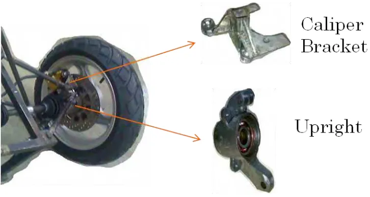
1.2.2 Upright Parts
The current upright designs have showed at Figure 1.3, uses a caliper bracket
in order to mount the brake caliper. With a new upright design, the use of caliper
5 Figure 1.3: Current Upright design
1.1.2 SCOPES
Below, there is some scope that I have been reserved for the exercise and
assists me in completing the project:
• To produce detail and 3 dimension design of the wheel upright component
using CAD software based on 2010 UTeM Formula Varsity specification and
regulation.
• To perform material selection and load analysis on the component
• To fabricate the upright component
6 CHAPTER 2
LITERATURE REVIEW
2.0 DESIGN REVIEW
![Figure 1.1: Suspension Assembly [29]](https://thumb-ap.123doks.com/thumbv2/123dok/566868.66993/19.595.119.565.343.556/figure-suspension-assembly.webp)
![Figure 1.2: Quarter Car Suspension Model [10]](https://thumb-ap.123doks.com/thumbv2/123dok/566868.66993/20.595.242.402.526.711/figure-quarter-car-suspension-model.webp)
![Figure 2.1: Design Core [36]](https://thumb-ap.123doks.com/thumbv2/123dok/566868.66993/24.595.200.436.72.377/figure-design-core.webp)
