This content has been downloaded from IOPscience. Please scroll down to see the full text.
Download details:
IP Address: 203.106.159.204
This content was downloaded on 16/12/2013 at 12:17
Please note that terms and conditions apply.
Development of formula varsity race car chassis
Development of formula varsity race car chassis
M A Abdullaha, M R Mansur, N Tamaldin and K Thanaraj
Centre for Advanced Research in Energy, Faculty of Mechanical Engineering, Universiti Teknikal Malaysia Melaka, Hang Tuah Jaya, 76100 Durian Tunggal, Melaka, Malaysia
E-mail: [email protected]
Abstract. Three chassis designs have been developed using commercial computer aided design (CAD) software. The design is based on the specifications of UTeM Formula VarsityTM 2012 (FV2012). The selection of the design is derived from weighted matrix which consists of reliability, cost, time consumption and weight. The score of the matrix is formulated based on relative weighted factor among the selections. All three designs are then fabricated using
selected materials available. The actual cost, time consumption and weight of the chassis’s are
compared with the theoretical weighted scores. Standard processes of cuttings, fittings and welding are performed in chassis mock up and fabrication. The chassis is later assembled together with suspension systems, steering linkages, brake systems, engine system, and drive
shaft systems. Once the chassis is assembled, the studies of driver’s ergonomic and part
accessibility are performed. The completion in final fittings and assembly of the race car and its reliability demonstrate an outstanding design for manufacturing (DFM) practices of the chassis.
1. Introduction
Based on the events of Formula SAE [1-2] and Formula Student [3], Universiti Teknikal Malaysia Melaka (UTeM) has started Formula Varsity in 2006 [4]. This biennial student level race competition
is initiated to test the undergraduate students’ analytical and technical skills in designing, analysing
and developing a single-seater race car [5-7]. In 2012, a team of second year Bachelor of Mechanical Engineering in Automotive (BMCA) students has developed the race car named UTeM Racing Team (URT). This race car is an improved design from the previous cars [8-11] and components [12-19]. A conceptual design based on hybrid composite [20] and electric [21] have also been developed. In previous report, 2 concepts have been designed, analyzed and fabricated [22-23]. However, the
chassis’s were fabricated to meet the specification [23] and based on available materials. This has led to material waste when the fabricated chassis was not used in actual race event due to its low reliability. In this extended report of chassis development, 3 chassis concept designs are compared. The selected design is undergone with detail static analysis, acceleration analysis, braking analysis, cornering analysis and stiffness analyses.
2. Methodology
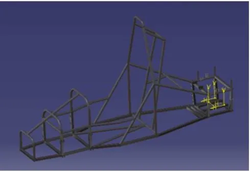
The CATIA V5 R20 CAR software is used in the development of chassis designs. Figure 1 – 3 show the concept designs. Table 1 tabulated the summary of each design. Table 2 shows the selection procedure based on the advantages and disadvantages of each design. Table 3 shows the actual components masses that included for the later stress analysis.
2nd International Conference on Mechanical Engineering Research (ICMER 2013) IOP Publishing IOP Conf. Series: Materials Science and Engineering50(2013) 012001 doi:10.1088/1757-899X/50/1/012001
Content from this work may be used under the terms of theCreative Commons Attribution 3.0 licence. Any further distribution of this work must maintain attribution to the author(s) and the title of the work, journal citation and DOI.
Figure 1. Concept design No. 1.
Figure 2. Concept design No. 2.
Figure 3. Concept design No. 3.
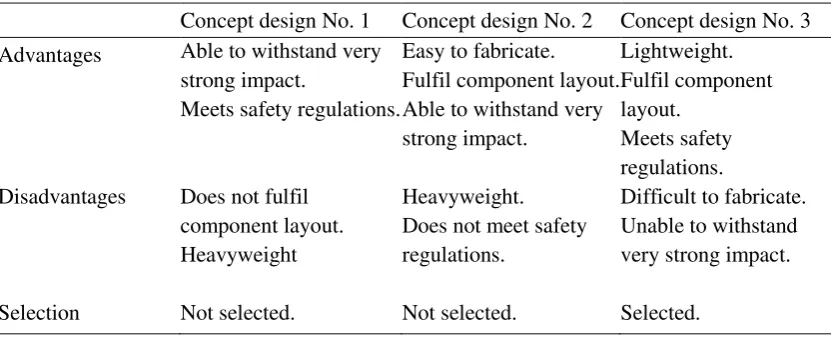
Table 1. Chassis concept designs.
Concept design No. 1 Concept design No. 2 Concept design No. 3
Chassis volume 0.004 m3 0.004 m3 0.003 m3
Material ASTM A36 ASTM A500 ASTM A500
Material density 7860 kg/m3 7850 kg/m3 7850 kg/m3
Yield strength 250 MPa 200 MPa 290 MPa
Theoretical Weight 31.761 kg 31.241 kg 21.857 kg
Poisson’s ratio 0.266 0.300 0.300
Material
Concept design No. 1 Concept design No. 2 Concept design No. 3
Advantages Able to withstand very
Selection Not selected. Not selected. Selected.
3. Analysis
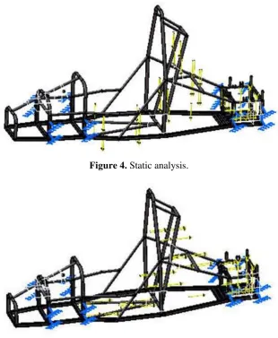
The total mass of the car with its components and driver (70 kg) is about 270.3 kg. This value is used in the Von Mises stress analysis. Figure 4 to 9 show the location of the forces and clamps for static, acceleration, braking, cornering, front stiffness and rear stiffness analyses respectively. As shown in Figure 4, for static case analysis, only the major components that were placed inside the chassis were considered. These weight components were the weight of the engine and the weight of the driver. The mass of the engine was 20 kg while the mass of the driver was approximately 70 kg which were about 200 N and 700 N respectively. The clamps were placed at all the parts of the chassis where the brackets were attached. The weight of the driver was distributed to the seat mountings while the weight of the engine was distributed to the engine mountings. The loads were directed downwards. In Figure 5, for acceleration analysis, only the major weight components of the car inside the chassis which were the engine and driver were considered. The loads and clamps were placed at the same parts of the chassis as in the static analysis. However, the loads were directed backwards, since, during acceleration, the engine and driver experience inertia whereby the mass of the driver and engine tends to stay where it was (pushing backwards) when the car was moving forward. In Figure 6, for braking analysis, the loads and clamps were placed at the same parts of the chassis as in the acceleration analysis. However, the loads were directed forward as during braking, the engine and driver experience inertia whereby the mass of the driver and engine tends to continue moving forward when the car is being stopped from moving forward.
2nd International Conference on Mechanical Engineering Research (ICMER 2013) IOP Publishing IOP Conf. Series: Materials Science and Engineering50(2013) 012001 doi:10.1088/1757-899X/50/1/012001
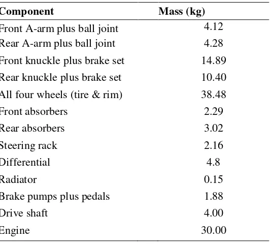
Table 3.Component’s mass.
Component Mass (kg)
Front A-arm plus ball joint 4.12
Rear A-arm plus ball joint 4.28
Front knuckle plus brake set 14.89
Rear knuckle plus brake set 10.40
All four wheels (tire & rim) 38.48
Front absorbers 2.29
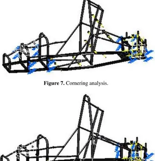
In Figure 7, the same magnitude of loads was distributed to the same mountings in the cornering analysis. However, the loads were directed to the side, as during cornering, the driver and engine experience inertia whereby the mass of the driver and the mass of the engine tends to stay where it was (pushing to the side way) as the car turns the other way. The front stiffness analysis was performed to test the stiffness at the front of the chassis as the chassis experiences torsion during cornering. As shown in Figure 8, the clamps were placed at parts of the chassis where the brackets at the back were attached. The load was divided at ratio of 40-60 whereby for front torsion, 40 % of the estimated total mass of the car was used (100 kg). This mass of 100 kg which is approximately 1000 N, placed at parts of the chassis where the brackets were attached at the front. The load was divided equally on both sides, one directing upwards while one directing downwards. The rear stiffness analysis was performed to test the stiffness at the back of the chassis as the chassis experiences torsion during cornering (Figure 9). As shown in Figure 9, the clamps were placed at parts of the chassis where the brackets at the front were attached. The load was divided at ratio of 40-60 whereby for rear torsion, 60 % of the estimated total mass of the car was used (150 kg). This mass of 150 kg which is approximately 1500 N, placed at parts of the chassis where the brackets were attached at the back. The load was divided equally on both sides, one directing upwards while one directing downwards.
4. Results and Discussion
Figure 10 – 15 show the stress distribution for each analysis. Figure 10 shows the Von Misses stress obtained from the analysis. The maximum stress obtained, which was 99.3 MPa, is the allowable stress while the yield stress (ultimate stress) of the material is 290 MPa. These values were used to calculate the factor of safety. The factor of safety was obtained by dividing the ultimate stress with the allowable stress which produced a value of 2.92. Figure 11 shows that for acceleration analysis, the maximum Von Misses stress value obtained was 52.8 MPa. The same method of calculation for factor of safety yielded a value of 5.49.
Figure 4. Static analysis.
Figure 5. Acceleration analysis.
Figure 6. Braking analysis.
2nd International Conference on Mechanical Engineering Research (ICMER 2013) IOP Publishing IOP Conf. Series: Materials Science and Engineering50(2013) 012001 doi:10.1088/1757-899X/50/1/012001
Figure 7. Cornering analysis.
Figure 8. Front stiffness analysis.
Figure 9. Rear stiffness analysis.
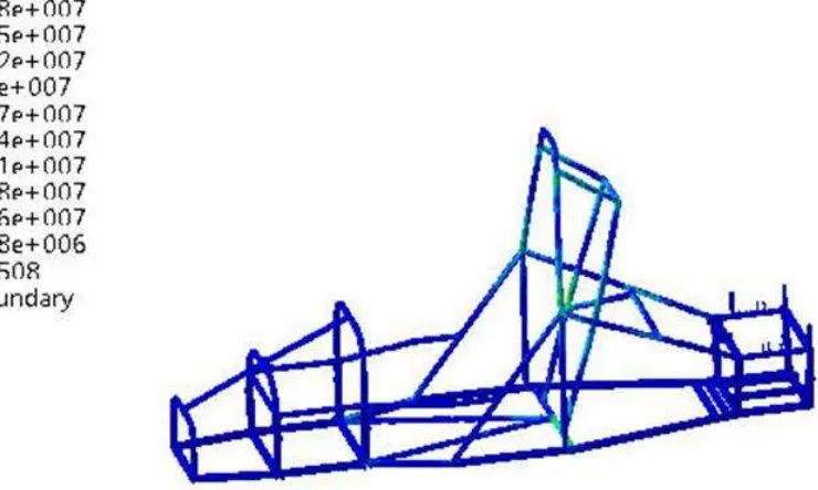
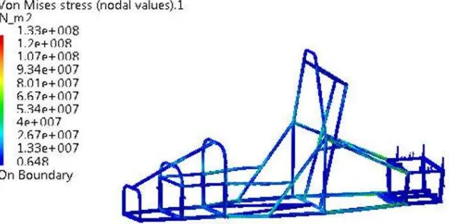
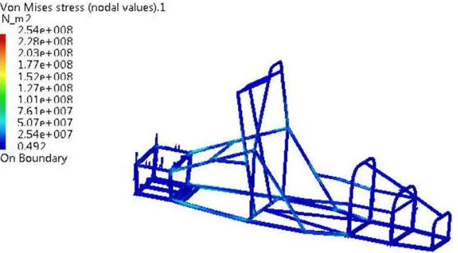
Figure 12 shows that for braking analysis, the maximum Von Misses stress obtained was same as in the acceleration analysis which was 52.8 MPa thus it yielded the same factor of safety, 5.49. Figure 13 shows that for cornering, the maximum value of Von Misses stress produced was 68.4 MPa. The corresponding calculation for factor of safety produced a value of 4.24. Figure 14 shows the maximum Von Misses stress value obtained from this analysis which was 133 MPa. When the yield stress of the material was divided by this value, it produced a factor of safety of 2.18. Figure 15 shows the maximum Von Misses stress value obtained from this analysis which was 254 MPa. When the yield stress of the material, 290 MPa was divided by this value, it produced a factor of safety of 1.14.
Figure 10. Stress distribution for static analysis.
Figure 11. Stress distribution for acceleration analysis.
2nd International Conference on Mechanical Engineering Research (ICMER 2013) IOP Publishing IOP Conf. Series: Materials Science and Engineering50(2013) 012001 doi:10.1088/1757-899X/50/1/012001
Figure 12. Stress distribution for braking analysis.
Figure 13. Stress distribution for cornering analysis.
Figure 14. Stress distribution for front stiffness analysis.
Figure 15. Stress distribution for rear stiffness analysis.
5. Conclusion
The simulation analysis results have established approving outcome in term of factor of safety at different loading tests. In overall, from all the analysis, conclusion can be made that the chassis was safe to be used. The factor of safety ranged from 1.14 to 5.49 which were acceptable. When the factor of safety is lower than 1, a structure is deemed to be unsafe. In industry a factor of safety ranging from 2-5 is preferred depending on the situation. In our case on the other hand, a factor of safety of 1 is also acceptable as this chassis was made for a one-off race event and not for durability. Thus, having a factor of safety equalling to 1 in certain situations is considered to be safe as the structure is strong enough to support the load while certain factors such as fatigue was not considered. If the factor of safety is too high, this would cause an unnecessary increase in cost and the mass of the chassis.
6. Acknowledgments
The authors gratefully acknowledged the financial support from Universiti Teknikal Malaysia Melaka and The Ministry of Higher Education, Malaysia (MoHE) under Exploratory Research Grant Scheme (ERGS), grant no.: ERGS/1/2012/TK08/UTEM/02/1/E00007.
[3] Institution of Mechanical Engineers (IMechE) 2012 Formula Student Competition Rules and Regulations IMechE.
[4] Universiti Teknikal Malaysia Melaka (UTeM) 2012 Formula Varsity 2012 Competition Rules and Regulations, UTeM.
[5] Sariman M F 2012 Merekabentuk dan Fabrikasi Casis Kerangka Ruang Kereta Lumba Elektrik Formula Varsiti UTeM (In Malay) Final Year Project Report Universiti Teknikal Malaysia Melaka (UTeM), Melaka, Malaysia.
[6] Ashari M H 2011 Design and Fabrication of Space Frame Chassis for UTeM Formula Style Race Car Final Year Project Report Universiti Teknikal Malaysia Melaka (UTeM), Melaka, Malaysia.
[7] Indral F 2010 Conceptual of a Single Seater Formula Racing Car Final Year Project Report Universiti Teknikal Malaysia Melaka (UTeM), Melaka, Malaysia.
2nd International Conference on Mechanical Engineering Research (ICMER 2013) IOP Publishing IOP Conf. Series: Materials Science and Engineering50(2013) 012001 doi:10.1088/1757-899X/50/1/012001
[8] Rahmat M S 2011 Design and Fabrication of Engine Mounting for UTeM Formula Style Race Car Final Year Project Report Universiti Teknikal Malaysia Melaka (UTeM), Melaka, Malaysia.
[9] Mohd Hashim M S 2010 Design and Development of Lightweight Chassis for UTeM Formula
Style Race Car Final Year Project Report Universiti Teknikal Malaysia Melaka (UTeM), Melaka, Malaysia.
[10] Shaharuzaman M A, Abdul Munir F, Hassan M Z, Mohamad Zin M R, Boejang H, Muhammad Farhan F H and Abdul Jamal A H 2010 Development of a Single Seat Race Vehicle for Educational Motorsport Engineering 3rd International Conference on Science & Technology: Applications in Industry & Education, 16-17 December 2010, Universiti Teknologi MARA, Pulau Pinang, MALAYSIA.
[11] Nasruddin F 2009 Design And Analysis Of The Drivetrain System For Formula SAE Race Car Final Year Project Report Universiti Teknikal Malaysia Melaka (UTeM), Melaka, Malaysia.
[12] Abdul Munir F, Munir, Shaharuzaman M A, Hassan M Z, Mohamad Zin M R, Mohd Azmi M I and Mat Nuri N R 2011 Components Design of a Single Seat Educational Race Vehicle Malaysian Technical Universities International Conference on Engineering & Technology (MUiCET 2011), 13-15 November 2011, UTHM, Batu Pahat, Johor.
[13] Mustaffa Albakri A A 2011 Design And Fabrication Of A Semi Automatic Gear Shifting Mechanism For UTeM Formula Style Race Car Final Year Project Report, Universiti Teknikal Malaysia Melaka (UTeM), Melaka, Malaysia.
[14] Suhaimi K 2011 Design And Fabrication Of An Upright With Brake Caliper Mounting For Formula Varsity Race Car Final Year Project Report Universiti Teknikal Malaysia Melaka (UTeM), Melaka, Malaysia.
[15] Daem M F 2011 Ergonomics Study Of Cockpit Arrangement For UTeM Formula Varsity Race Car Final Year Project Report Universiti Teknikal Malaysia Melaka (UTeM), Melaka,
[21] Othman M N 2012 Rekabentuk dan Fabrikasi Sistem Stering Kereta Lumba Elektrik Formula Varsiti UTeM (In Malay) Final Year Project Report Universiti Teknikal Malaysia Melaka (UTeM), Melaka, Malaysia.
[22] Abdullah M A, Mansor M R, Mohd Tahir M, Abdul Kudus S I, Hassan M Z and Ngadiman M N 2013 Analysis and Fabrication of Chassis Frame for UTeM Formula VarsityTM Race Car International Journal of Mining, Metallurgy & Mechanical Engineering (IJMMME) Volume 1 Issue 1 ISSN 2320–4060 (Online) 75-77.
[23] Abdullah M A, Mansor M R , Mohd Tahir M, Abdul Kudus S I, Hassan M Z and Ngadiman M N 2012 Analysis and Fabrication of Chassis Frame for UTeM Formula VarsityTM Race Car Proceeding for International Conference on Manufacturing and Industrial Engineering
(ICMIE’12) International Scientific Academy of Engineering & Technology (ISAET), Kuala Lumpur, Malaysia, (December 29th to 30th, 2012).