DESIGN AND FABRICATION OF AN UPRIGHT WITH BRAKE CALIPER MOUNTING FOR FORMULA VARSITY RACE CAR
KHALIS BIN SUHAIMI
This report is presented in
Partial fulfillment of the requirement for the Bachelor of Mechanical Engineering ( Automotive)
i
‘I/We* have read this thesis And from my/our* opinion this thesis
Is sufficient in aspect of scope and quality for awarding Bachelor of Mechanical Engineering (Automotive)’
Signatures : ...
Name of Supervisor I : En. Muhd Ridzuan Bin Mansor Date : ...
ii
DECLARATION
“I declare this report is on my own work except for summary and quotes that I have mentioned its sources”
iii
iv
ACKNOWLEDGEMENT
Considerable gratitude and many thanks goes to those who have helped making this final year project possible, as well as those who have contribute to this project or my education profile.
Special Thanks To: Suhaimi Bin Othman
Norhayati Binti Mohd Azmir En.Muhd Ridzuan Bin Mansor Leopard Racing Team
Organizer of Formula Varsity 2010 Especially:
v
ABSTRACT
vi
ABSTRAK
vii
TABLE OF CONTENT
CHAPTER TITLE PAGE
PREFACE i
DEDICATION ii
ACKNOWLEDGEMENT iv
ABSTRACT v
ABSTRAK vi
TABLE OF CONTENT vii
LIST OF TABLE xi
LIST OF FIGURE xii
LIST OF SYMBOLS xiii
LIST OF ABBREVIATION xvi
viii
CHAPTER 1 INTRODUCTION 1
1.0 Formula Varsity 1
1.1 Objective 3
1.2 Problem Statement 3
1.2.1 Upright Weight 3
1.2.2 Upright Parts 5
1.3 Scopes 5
CHAPTER 2 LITERATURE REVIEW 6
2.0 Design Review 6
2.0.1 Total Design Method 6
2.0.2 Design Error 7
2.1 Material Review 10
2.2 Machining Review 13
2.3 Analysis Review 13
2.3.1 Forces Acting On Suspension 15
2.3.2 Brake Force Equation 16
2.3.3 Finite Elemnet Analysis 17
CHAPTER 3 METHODOLOGY 18
3.0 Introduction 18
3.1 Project Flow Chart 19
3.2 Designing The Upright 20
3.2.1 Market Investigation 20
3.2.2 Product Design Specification 20
3.2.3 Conceptual Design 21
3.2.4 Detail Design 21
3.2.5 Fabrication 21
3.3 Material Selection 21
ix
3.4.1 Static Case 22
3.4.2 Lateral Force 24
3.4.3 Forces Determination 24
3.4.4 Structure Analysis 25
3.5 Fabrication Process 26
3.5.1 Process Coding 27
3.5.2 Machining 28
3.6 Fitting Process 34
CHAPTER 4 RESULT AND ANALYSIS 35
4.0 Total Design Method 35
4.0.1 Market Investigation ` 35
4.0.2 Conceptual Design 37
4.0.3 Evaluation and Selection of Concept 40
4.0.4 Design Rating 43
4.1 Material Selection 44
4.1.1 Material Comparison 45
4.2 Load Analysis 46
4.2.1 Static Analysis 46
4.2.2 Brake Force Calculation 49
4.3 Structure Analysis And Results 52
4.3.1 Structure Analysis 52
4.3.2 Result 54
4.4 Design Modification 54
4.4.1 Modification 54
4.4.2 Modified Upright Design Draft 55 4.4.3 Structure Analysis (modified upright) 56
x
CHAPTER 5 DISCUSSION 58
5.0 Upright After Fabrication Process 58
5.1 Weight Reduction 59
5.2 Component Reduced 60
5.2.1 Major Component 60
5.2.2 Subpart 60
5.3 Factor Of Safety 60
CHAPTER 6 CONCLUSION 62
5.0 Conclusion 62
5.1 Recommendation 63
REFFERENCES 64
xi
LIST OF TABLES
TABLE TITLE PAGE
2.1 AL6061-T6 properties 11
4.1 Weighting Factor 42
4.2 Design Rating 43
4.3 Material Properties 45
5.1 Upright Comparison 61
xii
LIST OF FIGURES
FIGURE TITLE PAGE
1.1 Suspension Assembly 2
1.2 Componet of Sprung and Unsprung mass 3
1.3 Quarter Car Suspension Model 4
1.4 Current Upright Design 5
2.1 Design Core 7
2.2 Failed Upright 7
2.3 FSAE Team Upright 8
2.4 Unreliable Design 9
2.5 Analyzed Upright Design 9
2.6 Sample Calculation 15
2.7 Forces acting on Upright 15
2.8 Example of Finite Element Analysis 17
3.1 Process Flow Chart 19
3.2 Static Loads On Level Ground 22
3.3 Use Of Electronic Scale 23
3.4 Free Body Diagram of Rear Suspension 24
3.5 Failed Upright at top maounting 25
3.6 Fabrication Process Flow Chart 26
xiii
3.8 After Drilling Process 29
3.9 After Roughing Process 29
3.10 After Pocketing And Pitting Process 30
3.11 After Contouring Process 30
3.12 Drilled Hole 31
3.13 Pocketed Area 31
3.14 After Third Process 32
3.15 T-slots Dimension 32
3.16 5mm Holes Drilled 32
3.17 Milled Area 33
3.18 Actual Hole Drilled 33
3.19 Glued T-slot 33
3.20 Fitted Upright 34
3.21 Full Assembly 34
4.1 F1 Upright 36
4.2 F1 Upright 36
4.3 Example Of Formula Student Uprights 36
4.4 Example of RC upright 36
4.5 Upright 1 38
4.6 Design Concept of Upright 1 38
4.7 Upright 2 38
4.8 Upright 3 38
4.9 Upright 4 39
4.10 Upright 5 39
4.11 Concept Generation Of Upright 5 40
4.12 Example of triangular pocket on an upright 41
4.13 Best example of triangular pocket 42
4.14 Rectangular Roughness Cornering 47
4.15 Rear Suspension Free Body Diagram 47
4.16 Realtions Between Master Pump and Caliper Piston 50
4.17 Forces Distribution On Upright 52
4.18 Torque Applied On The Caliper Mounting 52
4.19 Load and Constraint Setup before Analysis 53
xiv
4.21 Upright 5 55
4.22 Upright Modified 56
4.23 Upright Modified Technical Drawing 57
4.24 Load Distribution 56
4.25 Displacement Of The Upright 57
5.1 Weighing Both Upright 58
5.2 Caliper Mounts 60
5.3 Upright Body 60
5.4 New Upright 60
5.5 Location of Subpart Reduced 60
xv
LIST OF SYMBOLS
Θ1= angle (degree) Θ2= angle (degree) Θ3= angle (degree) Σ = Sigma
Π= 3.45
xvi
LIST OF ABBREVATIONS
RC= Remote Control F1= Formula One
FSAE= Formula Society Automotive Engineering CNC = Computer Numerical Control
xvii
LIST OF APPENDICES
NO TITLE PAGE
A Material Properties 69
B Technical Drawing 74
C Flow Chart And Gantt Chart 82
1
CHAPTER 1
INTRODUCTION
1.0 FORMULA VARSITY
Universiti Teknikal Malaysia Melaka (UTeM) Formula Varsity is an
international student racing competition that challenges students to
design, manufacture and race their single seat open-wheel formula style racing car in
real track condition. This event is inspired by similar student racing event such as
formula student and formula SAE. The events have provided a platform for
Malaysian student to practice their knowledge in engineering through motorsport
event. The event hope to foster the tie and collaboration between all Malaysian and
2
to help create the needed competent human capitals for our country automotive
industries.(http://formulavarsity.utem.edu.my)
The UTeM Formula Varsity 2010 team consists of 11 member crews that are
appointed for the car fabrication. After completion, several problems were founded
that affected the performance of the car, one of it was the weight of the car. This
project has been dedicated to reducing the upright component weight as it helps to
improve the performance of the car. Upright is stated as a linkage or a bracket to the
parts of suspension arms, transmission parts and brake parts.
Where:
UCA : Upper control arm
LCA : Lower control arm
TR : Tie Rod
PR : Push Rod
3
Vehicle upright assembly serves as a provider for physical
connections between wheel and suspension link, and to provide mounting for brake
caliper (Wong, 2007).
1.1 OBJECTIVE
To design and fabricate a wheel upright with brake caliper mounting for
UTeM Formula Varsity 2010 Race Car.
1.2 PROBLEM STATEMENT
1.2.1 Upright Weight
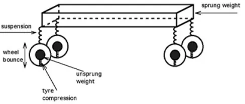
The mass of the vehicle body is called sprung mass and the mass of the running gear
together with associated components are called unsprung mass (Wong, 2001). The
upright is an unsprung mass, thus the shock absorber must control this load in
bumps. It is important to minimize the weight as it can reduce the force acting on the
shock absorber (David, 1999).
[image:21.595.200.444.572.676.2]
Figure 1.2: Component of Sprung and Unsprung Mass
4
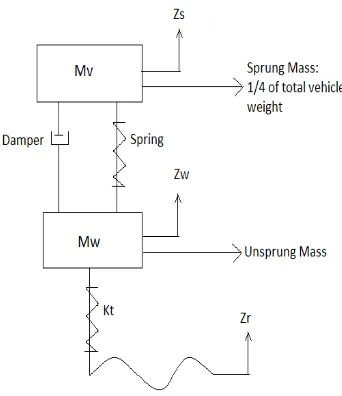
Where:
Mv: Sprung mass
Zs: Body vertical acceleration
Mw: Unsprung mass
Zw: Wheel vertical acceleration
Kt: Tire spring coefficient
[image:22.595.237.408.123.321.2]Zr: Road profile
5
1.2.2 Upright Parts
The current upright design uses a caliper bracket in order to mount the brake
caliper. With a new upright design, the use of caliper bracket can be eliminate and it
contribute to reducing number of parts. The advantages of reducing part is that it
contribute to weight reduction, improve reliability, enhancing performance
simplified maintenance and lower lifecycle cost (Frey et. al, 2006)
Figure 1.4: Current Upright Design
1.3 SCOPES
i. To produce detail and 3 dimension design of the wheel upright component
using CAD software based on 2010 UTeM Formula Varsity specification and
regulation.
ii. To perform material selection and load analysis on the component
iii. To fabricate the upright component
6
CHAPTER 2
LITERATURE REVIEW
2.0 DESIGN REVIEW