CONFIRMATION
‘I admit that have read this work and in my opinion this work was adequate from scope
aspect and quality to award in purpose Degree of Bachelor of Mechanical Engineering
(Automotive)’
Signature : ………
First Supervisor’s name : ………
DESIGN AND DEVELOPMENT OF VENTILATED SINGLE DISC BRAKE ROTOR
FOR UTeM FORMULA STYLE RACE CAR
MOHD FIRDAUS BIN ABU BAKAR
This technical report is submitted in accordance with the requirements of the Bachelor of
Mechanical Engineering (Automotive)
Faculty of Mechanical Engineering
Universiti Teknikal Malaysia Melaka
ii
DECLARATION
“I hereby, declare this thesis entitled Design and Development of Ventilated Single Disc
Brake Rotor for UTeM Formula Style Race Car at FKM, UTeM is the result of my own
research except as cited in the reference”
Signature : ………
Author name : MOHD FIRDAUS BIN ABU BAKAR
iii
DEDICATION
To my beloved father
Tn. Hj. Abu Bakar Bin Lachar
and to my beloved mother
Pn. Hjh. Mufidah Binti Embok Mohamad
because have been given their support and motivation for me to finish my study until
iv
ACKNOWLEDGEMENT
Firstly, alhamdulilah thanks to Allah S.W.T cause has been given this
opportunity to study until this level. During this level, this is the most of challenging part
of study for degree level where student must do their own project to qualify them to get
their degree scroll. I’m also not except involved in doing a project. Special thanks to my
supervisor, En. Muhd Ridzuan Bin Mansor because has been given his cooperation
during my projects. He also gives a motivation and inspiration for me to finish this
project.
I would like to thanks to my family especially my father and my mother because
giving their moral support to make me to finish my projects. I also want to thanks to all
my friends for giving their support during my stress on doing this project. This is an
enjoyable moment in my life where we can share our problem to our friends when our
morale is going down.
For the persons that I’m not mentioned their name, I also wants to thanks to them
who involve direct or indirect in my project. Without them, this thesis would become
v
ABSTRAK
Projek sarjana muda ini membincangkan tentang rekabentuk dan analisis piring
brek berongga yang baru bagi kereta lumba UTeM. Terdapat dua aktiviti yang terlibat
dalam penghasilan rekabentuk ini iaitu penghasilan rekabentuk yang baru dan analisa
termal. Bagi penghasilan rekabentuk, piring brek berongga telah dipilih dan dilukis
dalam bentuk 3D dengan menggunakan perisian berbantu komputer, CATIA V5R16.
Seterusnya, pemilihan bahan untuk piring brek telah dipilih iaitu Compacted Graphite
Iron (CGI). Selepas itu, analisa termal secara manual dijalankan untuk memastikan
prestasi bahan yang digunakan boleh beroperasi mengikut keadaan perlaksanaan
berdasarkan ciri-ciri termal bahan tersebut. Walaubagaimanapun, bagi memastikan
pengiraan yang persis dan tepat sehingga pengiraan pada tahap stabil, perisian berbantu
komputer, ABAQUS CAE v6.7-1 telah digunakan bagi membantu pengiraan Analisa
Unsur Terhingga. Selepas itu, perbandingan nilai boleh dilihat di antara nilai pengiraan
secara manual dengan nilai yang diperolehi daripada perisian. Analisa termal tekanan
vi
ABSTRACT
Projek Sarjana Muda presents a new conceptual design of a ventilated single
disc brake rotor developed for UTeM Formula Style race car. The development can be
divided into two activities which are creating a new design and thermal analysis. For
creating a new design, a single disc brake rotor with cross drilled was choose and a 3D
design was developed by using CATIA V5R16 computer aided software. Next, the
material was choose which is Compacted Graphite Iron (CGI) for this brake rotor.
Thermal analysis also performed by calculating manually to see the performance of this
material whether it can operate under the operating condition as well as it thermal
characteristic. To see the persist calculation of thermal analysis value until steady-state,
a computer aided software called ABAQUS CAE v6.7-1 was used to calculate the Finite
Element Analysis (FEA). Then, the value of load analysis can be compared to the value
that get from the software and manual calculation. The thermal stress analysis is conduct
vii
CHAPTER II LITERATURE REVIEW
2.1 History Formula SAE
viii
CHAPTER CONTENT
2.5 Heat Transfer
2.6 Finite Element Analysis (FEA) History 2.7 Finite Element Analysis (FEA)
2.8 ABAQUS Software
CHAPTER III METHODOLOGY
3.1 Introduction 3.2 Overall Process
3.3 Process Planning for this Semester 3.4 Design Process
3.5 Weight of the Disc Brake Rotor 3.6 Thermal Flow Calculation 3.7 Heat Transfer Equation 3.8 Material Selection
3.9 Finite Elements Modeling 3.10 Periodic Braking Option 3.11 Analysis Assumption
CHAPTER IV RESULTS
4.1 Theory Calculation for Ventilated Single Disc Brake Rotor
4.2 Specification of Performance and Dimension
4.3 Braking Method
4.4 Weight of New Concept Design 4.5 Thermal Flow Calculation 4.6 Heat Transfer Calculation
ix
CHAPTER CONTENT
4.7 Results of Simulation Using ABAQUS Software
CHAPTER V DISCUSSION
5.1 Final Design Advantage
5.2 Material Properties and Advantage 5.3 Disc Brake Cooling Properties
5.4 Weight Saving Achieve from this New Design Compared to the Current Disc Brake Used
5.5 Steady State Analysis 5.6 Transient Analysis 5.7 Temperature Distribution 5.8 Thermal Stress Analysis
CHAPTER VI CONCLUSION AND
x
LIST OF TABLES
NO. TITLE
2.1 Formula SAE car specification
(Source: http://sae.org/students/fsae-designspecs.xls)
3.1 Concept design selection
3.2 Disc brake rotor specifications
3.3 Comparison between Grey Cast Iron and CGI
3.4 Advantages and disadvantages of Gray Cast Iron
(Source: Dawson, 2004)
3.5 Advantages and disadvantages of CGI
(Source: Dawson, 2004)
3.6 Comparison between Transient and Coupled
Temperature-Displacement properties
4.1 Specification of the University of Toronto Formula
Motorsport (Source:
http://fsae.utoronto.ca/2002/car.html)
4.2 Dimension for new concept design
4.3 Result from load analysis
xi
LIST OF FIGURES
NO. TITLE
1.1 Formula SAE race car (http://fsae.eng.wayne.edu/)
2.1 Disc brake
2.7 Location of the disc brake inside the vehicle
(http://auto.howstuffworks.com/auto-parts/brakes)
2.10 Ventilated single disc brakes rotor
xii
2.12 Microstructure of Grey Cast Iron (Source: Warrick,
1999)
2.13 Microstructure of Compacted Graphite Iron (Source:
Warrick, 1999)
2.14 Heat transfer conduction application
(http://insulfix.xdesigns.com.au/Images/Conduction.
jpg)
2.15 Example of convection heat transfer
(http://www.physics.arizona.edu/~thews/reu/convection
1.bmp)
2.16 Radiation heat transfer
(http://coolexcooling.com/wp-content/uploads/2008/06/imagedisplayim.jpg)
2.17 Example of 3-D modeling FEA
(http://www.deskeng.com)
3.7 Second example of disc brake rotor
(http://cambriabike.com/Images/product/shimano_xtr_rt
96_rotor.jpg)
3.8 First new concept of disc brakes rotor
3.9 Second new concept of disc brakes rotor
3.10 New concept design that choose
3.11 Model geometry created using CATIA software
3.12 Flow for thermal stress analysis using ABAQUS
3.13 Graph of speed against time for one cycle braking
xiii
3.14 Graph of speed against time for ten cycle braking
3.15 Graph of heat flux against time for one cycle braking
3.16 Graph of heat flux against time for ten cycle braking
4.1 Speed against time in braking schedule (Source:
Gotowicki, 2005)
4.2 Parts of ventilated single disc brake rotor
4.3 The location of the hR values at disc brake rotor
4.4 Initial temperature of disc brake rotor
4.5 Visualization of cooling process using ABAQUS
software
4.6 Visualization of cooling process of one cycle brake fade
test using ABAQUS software
4.7 Visualization of temperature at cooling vanes for
transient analysis
4.8 Visualization of heating process for one cycle brake
fade test using ABAQUS software
4.9 Graph of temperature against time at node no of 488
4.10 3-dimensional (3D) views for contour of stress
distribution at second cycle of brake fade test
4.11 A front views for contour of stress distribution at
second cycle of brake fade test
4.12 A side views for contour of stress distribution at second
cycle of brake fade test
4.13 A located point of maximum Von Mises Stress at
second cycle of brake fade test
4.14 The graph of Von Mises Stress at disc against time for
disc brake rotor for ten cycle brake fade test
4.15 3-dimensional (3D) views for contour of deflection at
second cycle of brake fade test
xiv
4.16 A front views for contour of deflection at second cycle
of brake fade test
4.17 A side views for contour of deflection at second cycle
of brake fade test
4.18 A located point of maximum deflection occur at disc
brake rotor at second cycle of brake fade test
5.1 New Concept Design Selected
5.2 Graph of temperature distribution by theoretical
(Gotowicki, 2005)
5.3 Graph of Von Mises Stress against time (Akop, 2007)
77
78
78
79
85
xv
NOMENCLATURE
SAE = Society of Automotive Engineers
UTeM = Universiti Teknikal Malaysia Melaka
FAE = Finite Element Analysis
3D = Three Dimensional
CAD = Computer-aided Design
CATIA = Computer Aided Tridimensional Interactive Application
CGI = Compacted Graphite Iron
PSM 1 = Projek Sarjana Muda 1
PSM 2 = Projek Sarjana Muda 2
CAE = Computer-aided Elements
Ah = Area of cross-drilled holes, m2
As = Area of brake surface, m2
Ai = Area of inner cooling vanes, m2
Ap = Area of a part inside the cooling vanes, m2
AT = Total Area, m2
V = Volume, m3
Tdisc = Disc brake rotor thickness, m
= Density, kg/m3
= Mass, kg
KE = Kinetic Energy, J
∆
= Total Kinetic Energy, Jv = Vehicle Speed, m/s
L/Q = Braking Energy, J
xvi
qspecific = Heat Flux, kW/m2
Sflux = Brake Surface, m2
= Radius of disc brake rotor, m
= Radius of inner cooling vanes, m
= Angular speed of disc brake rotor, s-1
V = Viscosity of air, kg/ms
= Density of air, kg/m3
= Hydraulic diameter, m
= Average air velocity, m/s
= Dynamic air viscosity, Ns/m2
ℎ = Heat transfer, W/m2K
= Thermal conductivity of air, W/m.K
= Diameter of outer disc brake rotor, m
Re = Reynolds number
Pr = Prandtl number
l = Depth of cross-drilled holes, m
= Diameter of one cross-drilled holes, m
Rholes = Radius of one cross-drilled holes, m
= Diameter of outer cooling vanes, m
= Diameter of inner disc rotor, m
Ro-vanes = Radius of outer cooling vanes, m
Vavg = Average of air velocity, m/s
Vin = Velocity of air into the cooling vanes, m/s
Vout = Velocity of air out of the cooling vanes, m/s
Ain = Area of air into the cooling vanes, m2
Aout = Area of air out of cooling vanes, m2
Ndisc = Disc brake rotor speed, rpm
xvii
m = Meter
W = Watt
K = Kelvin
J = Joule
GPa = Giga Pascal
.igs = IGES
SI = International System of Units
∆ = Braking time, s ∆ = Stopping distance, m
Rtyre = Radius of tyre, m
1
CHAPTER I
INTRODUCTION
1.1 Introduction
Formula Society of Automotive Engineers (SAE) is a student competition
organized by SAE International that challenge students to design, build, develop and
working in one team to produce a small race car and compete to win the race. The
purpose of this race is to give an experience to the student in terms of technical
knowledge and soft skill in a problem based learning approach before they graduate and
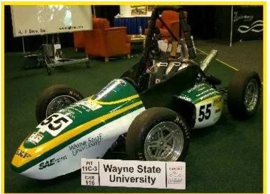
work as engineers after graduation later on. Figure 1.1 shows an example of completing
Formula SAE racing car.
Inspired by this event, Universiti Teknikal Malaysia Melaka (UTeM) has taken
similar initiative by organizing similar formula style competition called Formula
Varsity. The first competition was held in 2007 involving 2 teams from UTeM and
University Tun Hussein On. In October 2008, the second competition was organized
involving 5 teams from UTeM, Universiti Putera Malaysia, University of Nottingham
Malaysia, Politeknik Shah Alam, and Politeknik Kota Bharu. In order to win the
competition, many improvements created to the race car such as creating a lightweight
chassis. The braking system also include for this improvement in order to have an
2
A ventilated disc rotor that is used in braking system can be improved by
changing the material used. The material used must be having this characteristic which
are lightweight and also can be able to reach higher temperature. The most important
reason for have an efficient braking system is for the safety for the driver. By changing
the material of the ventilated disc rotor, the performance of the braking system can be
increased. Figure 1.1 shows an example of formula SAE race car.
Figure 1.1: Formula SAE race car (http://fsae.eng.wayne.edu/)
1.2 Objective
To create a new disc brake rotor for UTeM Formula Style race car and determine
thermal capabilities for the material choose using steady state and transient analysis
3
1.3 Problem Statement
Weight saving and material selected is important in producing a fast, efficient
and competitive race car. By reducing the weight and selected a suitable material of the
overall components without affecting the performance and the safety requirements. Due
to this problem, responding towards the weight saving and material choose, this project
will focus on developing a ventilated single disc brake rotor with a new weight and
material selection for UTeM Formula style race car.
1.4 Scope of Study
The scopes of this project are:
a) To produce detail design of the component using 3D CAD software, CATIA
V5R16.
b) To perform material selection for the component.
c) To calculate the load acting on the component during operation.
d) To perform linear thermal stress analysis of the component in steady state and
transient condition using Finite Element Analysis software, ABAQUS/CAE
4
CHAPTER II
LITERATURE REVIEW
2.1 History of Formula SAE
For the last 31 years ago, the formula SAE starts with only SAE Mini-Indy that
was held at the University of Houston. Dr. Kurt M. Marshek is a person who brings the
idea to create this competition that was inspired by a how-to article inside the Popular
Mechanics magazine. The vehicle was made out from wood and generates by five
horsepower Briggs and Stratton engine. The competition was joined by thirteen schools
and only eleven races and the winner is The University of Texas at El Paso. This
competition was guide by Mini Baja competition and involves the engineering student to
build their own small vehicle to race (http://en.wikipedia.org/wiki/Formula_SAE).
In 1980, Dr. Willian Shapton was come out with his idea of hosting the same
competition but no one wants to handle another Mini-Indy race. Three students at the
University of Texas at Austin come with new Mini-Indy proposal with a new rule after
finding the advantages and potential of the competition. The new rules give the
requirement to use any four stroke engine with 25.4 mm intake only. The University of
Texas at Austin becomes a host for the competition until 1984. During 1985, the
competition was hosted by The University of Texas at Arlington.
There are three biggest companies that become a host for this competition that
5
1992 competition, the three formed a consortium to run Formula SAE. Nowadays, the
event was sponsored through the company sponsorships and donations along with the
team’s enrollment fees (http://wikipedia.org/wiki/Formula_SAE).
2.2 Specification of Formula SAE
All of the competitors must follow the rules and regulation that is created by
Society of Automotive Engineers (SAE) to join this event. The car specification can be
divided into eight parts which are dimension, suspension parameter, brake system,
ergonomic, frame, power train, drivetrain and an aerodynamics. For braking system, the
aspects must be followed are diameter rotor must be 205 mm and using ventilated single
disc for front wheel while for rear wheel, the diameter of single disc must be 260 mm x
10mm. The braking system that acts on all four wheels must be operated by a single
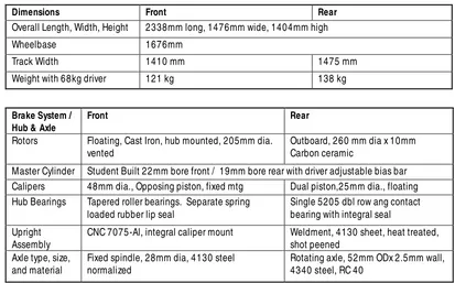
control and must be capable of locking all four wheels. Table 2.1 below shows the
Formula SAE specification which are related in the design of the braking system.
Table 2.1: Formula SAE car specification (http://sae.org/students/fsae-designspecs.xls)
Dimensions Front Rear
Overall Length, Width, Height 2338mm long, 1476mm wide, 1404mm high
Wheelbase 1676mm
Rotors Floating, Cast Iron, hub mounted, 205mm dia. vented
Outboard, 260 mm dia x 10mm Carbon ceramic
Master Cylinder Student Built 22 mm bore front / 19mm bore rear with driver adjustable bias bar Calipers 48mm dia., Opposing piston, fixed mtg Dual piston,25mm dia., floating Hub Bearings Tapered roller bearings. Separate spring
loaded rubber lip seal
Single 5205 dbl row ang contact bearing with integral seal
Upright Assembly
CNC 7075-Al, integral caliper mount Weldment, 4130 sheet, heat treated, shot peened
Axle type, size, and material
Fixed spindle, 28mm dia, 4130 steel normalized
6
2.3 Brake System
2.3.1 History of Brake System
A brake is a device for slowing or stopping the motion of a machine or vehicle or
alternatively a device to restrain it from starting to move again. The first braking system
that used in early years ago is a wooden block brake. This brake consists only a block of
wood and a lever system. This brake system operates when the driver pull a lever that
located near to him and the wooden block will touch against the wheel and decrease the
speed of the vehicle. This method is proved effective in both horse drawn or steam
powered vehicles. In 1980s, Michelin brothers starting replace the steel rimmed wheels
with the rubber tire and make wooden brakes system is useless because the wood cannot
have a conjunction with the rubber
(http://www.autorevolution.com/news/braking-systems-history-6933.html).
The next generation of braking system is drum brake system. This type of brake
is still used until today. In 1902, a French man called Louis Renault came out with his
idea and creating this type of brake which uses external system. Dust, heat and water
make them less effective. After years, the internal expanding shoes brake is introduce
which placing the shoes inside the drum brake and make the dust and water kept out in
terms of effective while braking.
At the end of 1918, Malcom Loughead, one of the founders which came up with
the idea to using hydraulic for all four wheel brake system. This system transfer the
force on the pressed pedal to the piston and then to the brake shoes. By using this
system, it makes the automotive sector in this world expended. After the hydraulic was
introduced by Loughead, a new design called disc braking system is created. The disc
brake system becomes popular around 1950s and at that time in Europe, the company