PJP/2011/FKM(1A)/S00855
DEVELOPMENT OF ELECTRIC FORMULA VARSITY RACE
CAR FOR GREEN CAMPUS
FADHLI BIN SYAHRIAL
FACULTY OF MECHANICAL ENGINEERING UNIVERSITI TEKNIKAL MALAYSIA MELAKA
PJP/2011/FKM(1A)/S00855
DEVELOPMENT OF ELECTRIC FORMULA VARSITY RACE CAR FOR GREEN CAMPUS
FADHLI BIN SYAHRIAL SAFARUDIN GAZALI HERAWAN
NAZRI BIN MD DAUD
RESEARCH VOTE NO: PJP/2011/FKM(1A)/S00855
FACULTY OF MECHANICAL ENGINEERING UNIVERSITI TEKNIKAL MALAYSIA MELAKA
ii DEVELOPMENT OF ELECTRIC FORMULA VARSITY RACE CAR FOR
GREEN CAMPUS
ABSTRACT
(Keywords: Electric car, Formula Varsity; Race car)
Among of motorsports events, the Formula Varsity organize by University Teknikal Malaysia Melaka (UTeM) is the most popular motorsports for higher education institutions. Formula Varsity was held once for two years. The main objective of this project is to design and develop a Electric Formula Varsity Race Car that consist of several components such as driver's cockpit, the strength and lightweight for the new design of control arm, the nose cone, and knuckle racing electric ear with high performance and reliability for the upcoming Formula Varsity race. Methods used for this project in accordance with the engineering design process and engineering software. The result of this project, a driver cockpit will be developing. At the end of this project, a new better cockpit and can satisfy the driver when use it will be develop and will be used for the next series of Formula Varsity race. The aspect of handling performance cannot be missed. Fabricating new design of control arm will need an initial view of the detail design. CATIA is 3D CAD modelling that help to create and develop a new design of control arm. With this software, the embodiment design for detail drawing can be done early and help us to proceed to fabricating process based on the clear dimensions to be measure on the element of fabricate. To check the effect of camber angle and other suspension geometry aspect for this project analysis, Adams/View providing a Real-time analysis for kinematics and dynamics analysis. The final fabrication will be test in real world to check the reliability and quality of the control arm. Development consisting on designing, analyzing and fabricating the nose cone section. The design must be tested for its aerodynamic in virtual and real world analysis using Ansyst-FLUENT software that been add-on into CATIA V5R20 designing software. The 3D model also will be generated to a scale. The best design will be mounted onto the Electric Racing Car for Formula Varsity 2012 event.
iii ACKNOWLEDGEMENTS
Alhamdulillah, with His Mercy and Blessings, this study was finally completed. The authors pleasure to express thank to Professor Madya Dr. Azizah bin Shaaban, as a Director of Centre of Research and Innovation Management (CRIM) and Dr. Noreffendy bin Tamaldin, Dean of Faculty of Mechanical Engineering, Universiti Teknikal Malaysia Melaka (UTeM) for giving us opportunity to conduct this research.
The authors are grateful to Dr. Musthafah bin Mohd Tahir, Deputy Dean of Research and Post Graduate Study, Faculty of Mechanical Engineering, also Staffs of the Faculty of Mechanical Engineering, and University-Industry Centre, UTeM, for their assistance and co-operation in carrying out the research in one way or another.
iv
1.1.2 Driver Seating Position 5
1.1.2.1 Arm Positioning 7
1.1.3 Ergonomics 8
1.1.3.1 Ergonomics Cockpit 9
1.1.3.2 The Driver’s Line Of Sight 10
1.1.3.3 The Steering Wheel Position 10
1.1.3.4 The Gauge Position 11
1.1.3.5 The Pedals, Gear Lever And Kill Switch 12
1.1.4 Ergonomics Seat 13
1.2 Aerodynamics in Formula One 17
1.2.1 Drag 18
1.2.2 Downforce 20
1.2.3 Streamline 21
1.2.4 Concept of Computational Fluid Dynamic (CFD) 23
v
1.2.6 Static Pressure Around The Aerofoil 25
1.2.7 Turbulence Model 26
vi
3.3.1 House of Quality (HOQ) 64
3.3.2 Product Design Specification (PDS) 65
3.4 Process of Designing 65
3.5 Selection of Materials 67
3.6 Catia V5 Software Modelling 67
3.7 Fabrication Process (Fiberglass Hand Lay-Up Process) 68
4.0 RESULTS AND DISCUSSION 69
4.1 Ergonomics 69
4.1.1 Design Process 69
4.1.2 Customer Requirements 70
4.1.3 QFD (Quality Function Deployment) 74
4.1.3.1 HOQ (House of Quality) 75
4.1.3.2 PDS (Product Design Specifications) 77
4.1.4 Conceptual Design 78
4.1.5 Solution Generation 79
4.1.5.1 First Conceptual Cockpit Design 80
4.1.5.2 Second Conceptual Cockpit Design 81 4.1.5.3 Third Conceptual Cockpit Design 82 4.1.6 Evaluation and Selection of The Concept 83 4.1.7 Evaluation Process of The Concepts Developed 86
4.1.8 Final Concept Cockpit Design 87
4.1.9 Concept Design of The Driver Seat 88
4.1.12.2 Eye Vision Analysis 98
4.1.12.3 Driver Seat Analysis 99
4.1.13 Fabrication 101
4.1.14 Discussions 107
vii
4.3.3 Complete Body Design 126
4.3.4 Analysis of Body 132
4.3.4.1 Drag Coefficient Analysis 133
4.3.4.2 Lift Coefficient Analysis 137
4.3.4.3 Streamline Analysis 140
4.3.4.4 Best Design Selection 144
4.4 Design of Knuckle 145
4.4.1 Conceptual Design 146
4.4.2 Evaluation and Selection of Concept 149
4.4.3 Design Rating 150
4.4.6 Structure Analysis and Results 159
4.4.6.1 Structure Analysis 159
4.4.6.2 Results 161
5.0 CONCLUSION 162
REFERENCES 164
viii LIST OF TABLES
TABLE TITLE PAGE
1.1 Types of fiberglass 17
1.2 Characteristics for road holding, road isolation,
and cornering a car's suspension 34
3.1 Comparison between fiberglass and carbon fiber 67
4.1 HOQ for the cockpit design 76
4.2 Application of digital logic method to criteria of cockpit 84
4.3 Weighting factor for criteria of cockpit 85
4.4 Evaluation process of the design developed 86
4.5 Rating Value 86
4.6 Comparison between fiberglass and carbon fiber 95
4.7 Total cost of raw material for fabrications process 107 4.8 Comparison between previous cockpit and new cockpit 108
4.9 Decision Matrix 116
4.10 Weight factor for specification criteria 117
4.11 Scoring sheet table for weight decision matrix 118
4.12 House of Quality of Design Selection 123
4.13 Summary of Analysis 144
4.14 Weighting Factor 150
ix LIST OF FIGURES
FIGURE TITLE PAGE
1.1 Illustration of the clearance required above the drivers head 4 1.2 95th % percentile male dimensions as depicted in the 2010 rules 4 1.3 Previous driver sitting position on UTeM Formula Varsity car 6
1.4 Sitting position on street car 6
1.5 Laying back sitting position 6
1.6 The 10 and 2 o’clock hand positioning 8
1.7 Human machine system 9
1.8 Formula one driver sight 10
1.9 The distance of steering wheel from the driver 11
1.10 RPM LED’s indicator (in circle) 12
1.11 The angle of the leg with disengaged pedals 13
1.12 Example of bucket seat types 13
1.13 The rearward inclined backrest position requires more
strain to sit and to stand 14
1.22 Fluid Velocity Different Between Top and Bottom of the Aerofoil 26 1.23 Example of Application in CFD for Turbulence Modelling 27
1.24 Fiber Glass CSM Mat 32
x 1.26 An extremely compact four-bar twist beam axle by Renault,
with two torsion bar springs both for the left
and right axle sides (items 4 and 8) 38
1.27 Instant center concept 43
1.28 Kinematics-instant axis concept 44
1.29 Roll center construction 45
1.30 Jacking effect with a high roll center 46
1.31 Camber change 47
1.32 Scrub is a function of IC height 47
1.33 Wheel path on rough road with a large amount of scrub 48 1.34 Derivation of braking anti features with outboard brakes 49
1.35 Braking anti features with inboard brakes 51
1.36 Front-wheel-drive anti-lift (or pro-lift) 51
1.37 Rear anti-squat, (a) solid axle and (b) independent rear suspension 51
1.38 Design Core 53
3.1 Method to gather information of the previous product 63
3.2 QFD product planning house (House of Quality) 64
3.3 Complete configuration of House of Quality 65
4.1 Total design method 69
4.2 The result of the first question about gender 70
4.3 The result of the second question about height 71
4.4 The result of the third question about weight 71
4.5 The result of the fourth question about seat types 72 4.6 The result of the fifth question about seating position 72 4.7 The result of the sixth question about steering position 73 4.8 The result of the seventh question about types of seat belt 74
4.9 View of the previous cockpit 79
xii
4.46 Elliptical Nose Cone 120
4.47 Spherical Blunted-Tangent O give Nose Cone 121
xiii
4.80 Upright 2 147
4.81 Upright 3 148
4.82 Concept Generation of Upright 1 148
4.83 Tensile Strength and Hardness of Plain Carbon Steels 152
4.84 Front Suspension Free Body Diagram 156
4.85 Relations between master pump and caliper piston 157
4.86 Forces Distribution on Upright 159
4.87 Torque Applied On the Caliper Mounting 159
4.88 Load Distribution 160
1
1.0 INTRODUCTION
Formula university is an event for teams of student to be applied their knowledge and skills for design, build, test, and race a small-scale formula style racing car. The development process include base theory of Automotive Engineering subject for car building by following all safety measure of automotive rules.
It also challenges the students to design, manufacture and race their single seat open-wheel formula style racing car in real track condition. This event is inspired by similar student based formula style racing events such as Formula SAE and Formula Student. The aim of the event is to provide a platform for Malaysian students with interest in motorsport engineering to put into practice their engineering knowledge and skills in developing a working model of a formula style racing car. The event hope to foster the tie and collaboration between all Malaysian and international higher education institutions especially among the students as well as to help create the needed competent human capitals for our country automotive industries.
Just like Formula SAE event, the students must complete their racing car by themselves with help from lecturers and technicians. The student should manage the team’s money in building the racing car and also finding sponsor for additional finances. The students also have to present their marketing strategies to the judges on how they manage their financial system and sponsorship. By this means, Formula Varsity is an event not only applied the students’ knowledge of engineering, but also applying the students’ knowledge of financial and marketing.
Formula Varsity event is an event that uses internal combustion engine taken from motorcycle under 135 cc. The engine must have single cylinder and a carburetor. The only allowed fuel to be used as the racing fuel is petrol.
2 electric motor with equivalent horsepower of 12 HP that as same as another 135 cc internal combustion engine.
For an electric racing car, the car must be light to avoid too much load to be put on the electric motor. This is because, if higher load is given to the electric motor, higher power consumption the motor will take. If the power consumption for the motor is high, more battery should be inserting on board the racing car and this will add more weight onto the car.
For these events, we are focusing in building lighter race car than the normal weight of the race car before. So, the new design must have considered the aspect of aerodynamic and weight of the front nose cone. To achieve the best aerodynamic for the Single Seated Formula Varsity Electric Racing Car, all the aspect should be taken into consideration. Aspects like the angle of attack of the front nose cone and wind displacer are essential in assuring that the racing car stay on the ground while traveling in high speed and high velocity wind. The racing car aerodynamic helping the car to travel in high speed much more stable and avoid the racing car from having a lift off from the ground.
Formula university is an event for teams of student to apply their knowledge and skills for design, build, test, and race a small-scale formula style racing car. The development process include base theory of Automotive Engineering subject for car building by following all safety measure of automotive rules.
Other thing that important is a Cockpit. In the cockpit, there are located steering wheel, driver seat, throttle and brake pedal and gauges. It is like a control room to the car. It is important to design a cockpit that can comfort the driver. Improper design of the cockpit can make the driver difficult and feel uncomfortable. Also it can affect the driver driving performance.
3 comfort while using an item increases its utility. The mental aspect of comfort in the human-machine interface is found in feedback. The look, feel, use and durability of a product will make a mental determination about a product or service. Better ergonomics means better quality which means it will be more comfortable with the value of the item.
For the control arm, the builder is should be focusing in building lighter race car than the normal weight of the race car before. So, the new design must have considered aspect for reliability, robustness and lighter control arm suspension. Also, the design for this concept of the suspension should have longer cycle time and can be test and use for many times.
The regulation of suspension design and development is fixed for independent suspension. Most of the competitor choosing double wishbone arm (known as double A-arm) for control arm of their formula car suspension. Hence, the new design of suspension must have an easy factor for fabricating and development process.
For the knuckle, the weight will affect the performance of the car. This project also focuses on reducing the upright component weight as it helps to improve the performance of the car upright or knuckle is stated as a linkage or a bracket to the parts of suspension arms, transmission parts and brake parts.
1.1 Ergonomics Seat in Cockpit
1.1.1 Competition Rules
Adhering to the rules that govern the chassis for the competition is a pivotal part of the research. If one small sub-section rule is not followed by the chassis, it will disqualify the whole car from the competition.
4 rules was created and broken down into all individual areas of the chassis layout. These areas were, Main Hoop, Front Hoop, Bulkhead, Main Hoop Bracing, Front Hoop Bracing, Bulkhead Support, Other Bracing and Side Impact Members. The design of the seat will determine the seating position of the driver it will affect the height of the roll cage and indirectly, will affect the chassis design.
Figure 1.1 : Illustration of the clearance required above the drivers head [1]
5 1.1.2 Driver Seating Position
6 Figure 1.3 : Previous driver sitting position on UTeM Formula Varsity car
Figure 1.4 : Sitting position on street car [3]
7 1.1.2.1 Arm Positioning
8 Figure 1.6 : The 10 and 2 o’clock hand positioning
1.1.3 Ergonomics
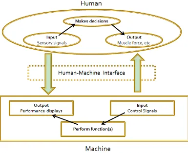
Ergonomics is concerned with the design of system in which people carry out work. Its name comes from the Greek words ergon which means “work” and nomos which means “law” [4]. When designing any system where humans and machine work together to produce something, we need to know about the characteristics of the people involved and be able to apply this knowledge to the design. This activity is the fundamental function of ergonomics. Ergonomics aims to ensure that human needs for safe and efficient working are met in the design of work systems. Figure 1.7 show the human machine system. Ergonomics needs to be considering enhancing desirable human value such as [5]:
i. Improved safety of the product. ii. Reducing fatigue strength and stress. iii. Increased comfort to the user.
9 Figure 1.7 : Human machine system
1.1.3.1 Ergonomics Cockpit
10 1.1.3.2 The Driver’s Line Of Sight
The driver visibility is the main importance factor in cockpit. The main factor in designing cockpit is to ensure enough vision of the track in front, and enough visible sight on the left and right. The side mirrors also should place as an extension of the visible field. The driver doesn’t need to turn their neck to view the side mirror. Just need to drive their eye in small angle to see the side mirror. Figure 1.8 show the driver vision while driving the open wheel racing car.
Figure 1.8 : Formula one driver sight
1.1.3.3 The Steering Wheel Position
![Figure 1.2 : 95th % percentile male dimensions as depicted in the 2010 rules [1]](https://thumb-ap.123doks.com/thumbv2/123dok/559872.66077/18.595.158.512.496.658/figure-th-percentile-male-dimensions-depicted-rules.webp)
![Figure 1.4 : Sitting position on street car [3]](https://thumb-ap.123doks.com/thumbv2/123dok/559872.66077/20.595.218.418.302.467/figure-sitting-position-street-car.webp)