DESIGN AND FABRICATION OF SPACE FRAME CHASSIS FOR UTeM FORMULA STYLE RACE CAR
MUHAMAD HAFIZULLAH ASHARI
‘I have read this thesis and from my opinion this thesis
is sufficient in aspects of scope and quality for awarding Bachelor of Mechanical Engineering (Automotive)’
Signatures : ………...
Name of Supervisor I : En. Muhd Ridzuan Mansor
DESIGN AND FABRICATION OF SPACE FRAME CHASSIS FOR UTEM FORMULA STYLE RACE CAR
MUHAMAD HAFIZULLAH BIN ASHARI
This report is presented in partial fulfillment of the requirements for the honor of Bachelor of Mechanical Engineering (Automotive)
Faculty of Mechanical Engineering Universiti Teknikal Malaysia Melaka
“I declare this report is on my own work except for summary and quotes that I have mentioned its sources”
Signature : ………..
iii
ACKNOWLEDGEMENTS
I would like to express my gratitude to all those who gave me the possibility to complete this project. I want to thank to Allah S.W.T for giving me good health to do the necessary research work. I have furthermore to thank my fellow friends who encouraged me to go ahead with my project.
I am deeply indebted to my supervisor, Mr. Muhd Ridzuan bin Mansor from the Faculty of Mechanical Engineering Department whose help, stimulating suggestions and encouragement helped me in all the time of research and writing of this Projek Sarjana Muda (PSM).
I thank the laboratory management especially the lab technicians for their cooperation and support and also not leas thank my friend Mohd Zaini, Mohd Sabirin, Mohd Faliq, Amar Ridzwan, Kamal Khalid and Ammar Alfaiz for all thier assistance on generating the use of Catia programming and fabrication chassis. My housemates, who were great, help in difficult times.
Lastly, I would like to give my special thanks to my parents whose patient love enabled me to complete this work, sacrifice their money for hoping me that I can finish my project on time. I hope that all that have been study and research in this thesis can be use as references to the other student in the future
v
ABSTRACT
ABSTRAK
vii
TABLE OF CONTENT
CHAPTER TITLE PAGE
DECLARATION ii
DEDICATION iii
ACKNOWLEDGEMENT iv
ABSTRACT v
ABSTRAK vi
TABLE OF CONTENT vii
LIST OF TABLES xii
LIST OF FIGURES xiii
LIST OF APPENDICES xvi
I INTRODUCTION 1
1.1 Project Introduction 1
1.2 Objective 2
1.2 Problem Statement 2
II LITERATURE REVIEW 7
2.1 Introduction 7
2.2 Competition Rule 8
2.3 Spaceframe History 10
2.3.1 Current Frame 10
2.4 Types of Chassis Design 11
2.4.1 Ladder Frame 11
2.4.2 Space Frame 11
2.4.3 Backbone Chassis 11
2.4.4 Monocoque 12
2.5 Material for Chassis Construction 14
2.5.1 Steel 14
2.5.1.1 Plain Carbon Steel 14
2.5.1.2 Mild steel 15
2.5.1.3 Medium Carbon Steel 16
2.5.1.4 High Carbon Steel 16
2.5.1.5 Alloy Steel 16
2.5.1.6 Stainless Steel 16
2.5.2 Aluminium 17
2.6 Torsional Stiffness 18
2.7 Fabrication Techniques 20
III METHODOLOGY 21
ix
3.2 Analysis of Current Chassis 21
3.3 Modeling of Spaceframe Chassis 22
3.3.1 Process 22
3.3.2 Literature Review and Finding Information
25
3.3.3 Selection Material 25
3.3.4 Selection of Design 26
3.3.5 CATIA V5 Software Modeling 27 3.3.6 Finite Element Analysis 27
3.4 Fabrication Process 29
3.4.1 Gas Metal Arc (MIG) 29
IV DESIGN AND MATERIAL SELECTION 31
4.1 Design
4.1.1 Introduction 31
4.1.2 Total Design Method 31
4.1.3 Market Investigation 32
4.1.4 Product Design Specification 34
4.1.5 Conceptual Design 35
4.1.6 Solution Generation 36
4.1.7 Evaluation and Selection of Concept 40 4.1.8 Evaluation Process of the Concepts 44
4.1.9 Compliance to Rules 46
4.2 Material Selection 49
4.2.1 Introduction 49
4.2.2 Comparisons 49
4.2.3 Conclusion 51
V DESIGN ANALYSIS 53
5.1 Introduction 53
5.2 Define Load 54
5.3 Torsion Displacement Analysis 55
5.4 Bending Stress Analysis 57
5.5 Analysis Results 58
5.5.1 Torsional Displacement Front Side 58 5.5.2 Torsional Displacement Rear Side 59
5.5.3 Bending Stress 60
5.6 Result of Chassis Structural Analysis 60
VI FABRICATION 62
6.1 Introduction 62
6.2 Project Planning 64
6.3 Material Purchasing 64
6.4 CAD Drawing and Dimensions 65
6.5 Chassis Construction 66
xi
VII RESULT AND DISCUSSION 74
7.0 Introduction 74
7.1 Weight Reduction 74
7.2 Stress Analysis Result 76
7.3 Comparison of Structural Analysis Result with Other Researchers
78
7.4 Design and Fabrication 81
7.5 Manufacturing Costing 82
VIII CONCLUSION AND RECOMMENDATION 83
8.1 Conclusion 83
8.2 Recommendation 84
References 85
Appendix A UTeM Formula Varsity 2010 Regulation
90
LIST OF TABLES
TABLE TITLE PAGE
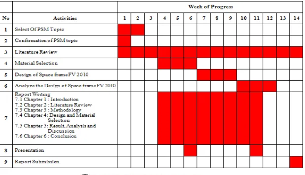
1.1 Gantt Chart PSM 1 4
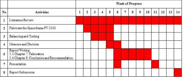
1.2 Gantt Chart PSM 2 5
2.1 Comparison of Each Type of Chassis Design 13 4.1 Product Design Specification of Formula Varsity 2010
SpaceFrame Chassis
34
4.2 Application of Digital Logic Method to Criteria of SpaceFrame Chassis
41
4.3 Weighting Factor for Criteria of SpaceFrame Chassis 42
4.4 Rating Value 44
4.5 Evaluation Process of the Design Developed 45 4.6 Comparison Among the Material Applicable for Chassis
Construction
50
4.7 Material Properties of Low Carbon Steel 51
5.1 Structural Analysis Result of the New Chassis 64 7.1 Compare Weight Previous Design and New Design 75
7.2 Torsion and Bending Analysis Result 76
xiii
LIST OF FIGURES
FIGURE TITLE PAGE
1.1 Basic Formula Student Race Car 2
1.2 Overall Flow Process Chart 6
2.1 Illustration of the Side Impact Members Location 8 2.2 Illustration of the Clearance Required Above the Drivers Head 9 2.3 95th % Percentile Male Dimensions as Depicted in the 2010
Rules
9
2.4 Steel 14
2.5 Tensile Strength and Hardness of Plain Carbon Steels 15
2.6 Stainless Steel. 17
2.7 Aluminum 17
2.8 Example of Frame Chassis in Torsion 18
2.9 Free Body Diagram Viewed from Front Suspension Bay 19
2.10 Section Joining 20
3.1 Current SpaceFrame Chassis 22
3.2 Overall Flow Process 24
3.3 Block Diagram of Design Process 26
3.4 Properties of Material is Define 28
3.5 Process Schematic of MIG 30
4.2 Current SpaceFrame Chassis 36
4.3 First SpaceFrame Chassis Design 37
4.4 Second SpaceFrame Chassis Design 38
4.5 Third SpaceFrame Chassis Design 39
4.6 Weighting Factor of Criteria 43
4.7 The Test Dummy Modeled to Test for Clearance from Role Hoops
46
4.8 Chassis Design that have 95th Percentile Manikin 47
4.9 Final Chassis Design 48
4.10 Selected Material Applied on Chassis 52
5.1 Free Body Diagram Load Distribution 54
5.2 Location of Applied Load and Constraint for Torsion Displacement Analysis at Front Side.
56
5.3 Location of Applied Load and Constraint for Torsion Displacement Analysis at Rear Side
56
5.4 Location of Applied Load and Constraint for Bending Stress Analysis on the Overall Chassis
57
5.5 Torsional Displacement for Front Side 58
5.6 Torsional Displacement for Rear Side 59
5.7 Bending Stress on Overall Chassis 60
6.1 Fabrication Flow Chart 63
6.2 The Breakdown Structure of Chassis 64
6.3 Detail Drawing and Dimension 65
6.4 The Full Scale of Design is Template on Trace Paper 66
6.5 The Pipe is Cut by the Disc Cutter 66
xv
6.7 Frame is Jig by Nails with Template on Full Scale Dimension 68
6.8 The Welding Process 68
6.9 Grinding Procedure 69
6.10 Frame is Positioning in Straight Line 69
6.11 Engine Bay is Fully Construction 70
6.12 Finish All Welding Work 70
6.13 Final Design is Fully Constructed 71
6.14 Chassis is Check for the Sufficient in all Areas of the Dimensions and Construction
71
6.15 Grinding to Remove Surplus of Welding 72
6.16 Painting the Final Product 72
6.17 Weighting Scale Calibration with Constant Mass 5kg 73
6.18 Weighting the Final Product 73
7.1 Comparison Analysis Results for Ratio of Torsional Stiffness per Weight with Other Researchers
79
7.2 Comparison Analysis Results for Torsional Stiffness with Other Researchers
79
LIST OF APPENDICES
NO TITLE PAGE
A UTeM Formula Varsity 2010 Regulation 90
B Material Properties 94
1
CHAPTER I
INTRODUCTION
1.1 Project Introduction
Spaceframe chassis have been in use since the start of the motor sport scene. A spaceframe consists of steel or aluminum tubular pipes placed in a triangulated format to support the loads from the vehicle caused by; suspension, engine, driver and aerodynamics.
There are two main types of chassis used in race cars, steel spaceframes and composite monocoque. Although spaceframes are the traditional style they are still very popular today in amateur motorsport. Their popularity maintains because of their simplicity, the only tools required to construct a spaceframe is a saw, measuring device and welder.
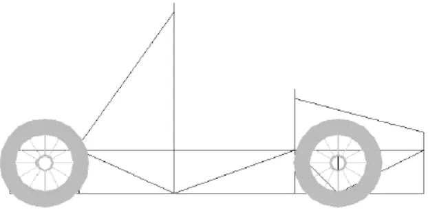
Figure 1.1: Basic Formula Student Race Car (Baker, 2004)
1.2 Objective
The main objective of this project is to design, analyze and fabricate a new spaceframe chassis for UTeM formula style race car. New chassis must comply with the rule and regulation stated in the Formula Varsity 2010 competition.
1.3 Problem Statement
The design of a chassis for a 2010 UTeM Formula Varsity Race Car must contain all necessary components to support the car and the driver. It must also comply with the Formula Varsity 2010 rules. In order to produce a competitive vehicle with optimum chassis performance, many areas need to be studied and tested.
3 There was some factor that can effected weight of a vehicle which is the types of material used, the diameter or dimension of tubes use to built space frame chassis, and also the design geometry of chassis.
This project carried out all of the necessary background research required to sustain an accurate database of design criteria. Design criteria then allowed the design process and methodology to be derived and to allow for smooth construction of an efficient and effective space frame chassis. Once construction of the chassis was completed, analyses were conducted to investigate the effects of working loads on the chassis. Finite element analysis was used to simulate the conditions of various load combinations.
1.4 Scope
i. To produce detail and 3D design of the chassis using CATIA based on 2010 UTeM Formula Varsity specification and regulation.
ii. To select suitable material for the chassis through material selection analysis. iii. To calculate the load acting on chassis during operation.
iv. To perform the static Finite Element Analysis to the chassis.
v. To evaluate the torsional stiffness foe the chassis based on the load analysis using CATIA
5 GANTT CHART PSM 2
FLOW CHART
Figure 1.2: Overall Flow Process Chart Design of Space
Frame FV 2010
Material Selection
Analyze the Space Frame FV 2010
Fabricate
Balancing and Finishing
Decision Making
Report Writing
End Progress Literature Review
Fail
Pass