DESIGN AND DEVELOPMENT OF HYBRID COMPOSITE CHASSIS FOR FORMULA STUDENT RACE CAR
MOHD FIRDAUS BIN ZAMRI
‘I/We* admit that have read this dissertation and in my/our* opinion this dissertation is satisfactory in the aspect of scope and quality for the bestowal of
Bachelor of Mechanical Engineering (Automotive)’
Signature :………
Supervisor 1’name : Mr. Muhd Ridzuan Bin Mansor
Date :………
Signature :………
Supervisor 2’name : Mr Mohd Hanif bin Harun
DESIGN AND DEVELOPMENT OF HYBRID COMPOSITE CHASSIS FOR FORMULA STUDENT RACE CAR
MOHD FIRDAUS BIN ZAMRI
This report is submitted to the Faculty of Mechanical Engineering in partial fullfilment of the partial requirement for awarding the
Degree of Mechanical Engineering (Automotive)
Faculty of Mechanical Engineering Universiti Teknikal Malaysia Melaka
“I admit that this report is my own work except the summary and some statement which is each of them,
I already state the source of it”
Signature : ……….
ACKNOWLEDGEMENTS
First and foremost, all praises to Allah the Almighty that by His blessings I have been able to complete Projek Sarjana Muda (PSM), which is part of the course requirement that I am undergoing in Universiti Teknikal Malaysia Melaka (UTeM). Specifically, my utmost gratitude goes to these individuals who have contributed immeasurable amount of guidance, advice and assistance along the project period;
My dedicated supervisor, En. Muhd Ridzuan Mansor, who has supportively guiding and teaching a lot of valuable knowledge, also for the opportunities he has given me in exposing myself to research and development environment.
The dedicated staffs in Faculty of Mechanical Engineering and Faculty of Manufacturing Engineering for the time and their valuable advice and guidance when solving the problem.
The supportive BMCA fellows for lending their hands and giving continuous supports during my project period to achieve the objective of study.
Last but not least, to my family for their supports, praises and helps all the way during this project being implemented. I really appreciate and grateful for what they have done.
ABSTRACT
ABSTRAK
TABLE OF CONTENTS
ACKNOWLEDGEMENTS ... i
ABSTRACT ... ii
ABSTRAK ... iii
LIST OF FIGURES ... viii
LIST OF TABLES ... x
LIST OF APPENDIX ... xi
1 INTRODUCTION ... 1
1.1 Objective of study ... 3
1.2 Problem statement... 3
1.3 Scopes of study ... 4
1.4 Benefit of study ... 4
2 LITERATURE REVIEW ... 5
2.1 Formula SAE ... 6
2.2 Introduction to chassis system ... 7
2.2.1 Types of Chassis ... 9
2.2.2 Load Determination ... 12
2.2.3 Crashworthiness ... 15
2.3.2 Reinforcing Fibers ... 18
2.3.3 Manufacturing Process ... 21
2.3.4 Resin Transfer Molding ... 22
3 THEORY... 24
3.1 Vehicle Dynamics ... 25
3.1.1 Static Axle Load ... 25
3.1.2 Center of Gravity... 27
3.1.3 Torsional Load ... 29
3.1.4 Dynamic Axle Load ... 30
3.2 Composite calculation ... 31
4 RESEARCH METHODOLOGY ... 33
4.1 Flow Chart for PSM 1 ... 34
4.2 Flow Chart for PSM 2 ... 35
4.3 Details Process in PSM 1 ... 36
4.3.1 Problem Description ... 36
4.3.2 Literature Review ... 36
4.3.3 Design Specification and Requirement ... 37
4.3.4 Concept Design Generation ... 37
4.3.5 Load Calculation ... 38
4.3.6 Composite Calculation ... 39
4.4 Details Process in PSM 2 ... 40
4.4.1 Fabrication of Design ... 40
4.4.2 Result and Discussion, Recommendation and Conclusion ... 41
4.5 Methodology – Welding Process ... 41
5 CHASSIS DESIGN ... 47
5.1 Design Requirement... 48
5.2 Concept Generation ... 49
5.2.1 Concept Design 1 ... 50
5.2.2 Concept Design 2 ... 51
5.2.3 Concept Design 3 ... 52
5.3 Weighted Rating Method ... 53
5.4 Final Concept Selection ... 54
5.5 Estimated Weight of Final Concept Design ... 55
6 LOAD CALCULATION ... 56
6.1 Static Axle Load ... 57
6.2 Center Of Gravity ... 59
6.3 Torsional Load ... 60
6.4 Dynamic Axle Load ... 61
6.5 Composite calculation ... 63
7 RESULT AND DISCUSSION ... 68
7.1 Design of product ... 69
7.2 Welded frame ... 69
7.3 Composite structure ... 69
9.1 Load Calculation ... 73
9.2 Composite Calculation and Actual Test... 74
9.3 Improving Existing Design ... 74
9.4 Perform FE Analysis And Ergonomics Analysis On The Designed Chassis ... 75
9.5 Consider Aerodynamic Effect ... 76
9.6 Improve Fabrication Technique and Process ... 77
9.7 Producing Smooth Surface ... 78
REFERENCE ... 79
LIST OF FIGURES
Figure 1 : Composite chassis for Formula 1 race car (Source:
http://www.one-pablo.com/technique/chassis1.jpg) ... 2
Figure 2 : Chassis of Lamborghini Diablo (Source: www.fast-cars.ch) ... 10
Figure 3 : Chassis of Porche Carrera GT (Source: www.fast-cars.ch) ... 11
Figure 4: Example of ladder chassis (Source: www.autozineschool.com) ... 11
Figure 5 : Example of backbone chassis (Source: www.autozineschool.com) ... 12
Figure 6 : Longitudinal torsion acts on vehicle (Source: Ripley and George, 2002) .... 13
Figure 7 : Vertical bending load torsion acts on vehicle (Source: Ripley and George, 2002) ... 14
Figure 8 : Lateral bending load acts on vehicle (Source: Ripley and George, 2002) .... 14
Figure 9 : Classify of composite (Source: Yuzhairi, 2008)... 16
Figure 10 : Fiberglass (Source: http://en.wikipedia.org/wiki/Fiberglass) ... 19
Figure 11 : Carbon fiber (Source: http://en.wikipedia.org/wiki/Carbon_fiber) ... 20
Figure 12 : Hand lay-up process (Source: Yuzhairi, 2008)... 22
Figure 13 : Resin transfer molding (Source: Mallick, 1993) ... 22
Figure 14 : Diagram of VARTM process (Source: Mallick, 1993) ... 23
Figure 15 : Acted force on the vehicle ... 25
Figure 16 : Location center of gravity ... 27
Figure 19 : Flow chart for PSM 1 ... 34
Figure 20 : Flow chart for PSM 2 ... 35
Figure 21 : Flow Chart of concept design generation ... 37
Figure 22 : Flow Chart for load calculation ... 38
Figure 23 : Flow Chart of composite calculation ... 39
Figure 24: Flow chart for fabrication process ... 40
Figure 25: Cutting angle... 42
Figure 26: Welding process ... 42
Figure 27: Mold design ... 43
Figure 28: Mold design after changed ... 44
Figure 29: Mold with wrapping plastic ... 44
Figure 30: Mold with wrapping plastic ... 46
Figure 31: Final product ... 46
Figure 32: Concept design 1 ... 50
Figure 33: Concept design 2 ... 51
Figure 34: Concept design 3 ... 52
Figure 35 : Final concept design ... 54
Figure 36: Layer of composite ... 63
Figure 37: Trapped air in the composite layer... 70
Figure 38: Area with sharp edge ... 75
LIST OF TABLES
Table 1 : Comparison between glass, carbon and aramid fiber composites... 21
Table 2 : Weighted Rating Method ... 53
Table 3 : Rating value ... 53
LIST OF APPENDIX
Appendix A: Gantt Chart………..81
Appendix B: Supplier’s description of glass fiber and resin……….82
Appendix C: Formula SAE Rules 2008………86
CHAPTER 1
1 INTRODUCTION
Chassis is widely used in vehicle design to give a support for all components. It has been study heavily to improve the performance of the car and create a suitable one for different type of vehicle. In the race car event, chassis is built to boost it until a limit with the intention of win over challenger. Chassis of a vehicle is usually designed with purpose to hold the load from the components of vehicle and mass from driver and passenger. Chassis need to satisfy a number of requirements whose aims partly conflict because of different operating conditions which are loaded and unloaded weight, acceleration and braking force, level or uneven road and straight running or cornering.
from university by following the standard policy set by Society of Automotive Engineering (SAE). It is called Formula SAE which gives opportunities to the students to produce a Formula-style race car and create a starting base about development of racing car. This will gives the opportunity to apply the theories from textbook to real work place and also come with clever problem solving of racing car.
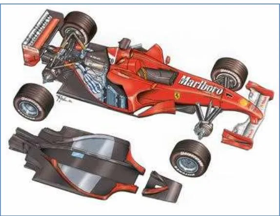
Presently, Universiti Teknikal Malaysia Melaka (UTeM) had developed a racing car using a chassis made from the mild steel. However, this race car does not apply to the SAE standard. The chassis system used now is tubular type. Thus, in order to increase it performances and abide to the SAE standard, the new development of chassis is needed. The idea is to optimize the characteristics of chassis and hence, the performance of the racing car by changing its material from mild steel to Glass Fiber Reinforced Polymer (GFRP).
Figure 1 : Composite chassis for Formula 1 race car
The purpose of the study is to develop a composite space frame chassis by using Glass Fiber Reinforced Polymer (GFRP) composite for formula student racing car.
1.2 Problem statement
The current racing car use tubular or space frame chassis system built from mild steel with diameter approximately 1 inch. The complexity of design and the arrangement of the components contribute a waste space which not makes the car more compact. By using of mild steel tubes has cause the overweight of the car and makes the car lose the power. Analysis on the chassis has not been done during development which is essential to know the load distribution and the strength of component during worst case scenario. Without any CAD data of design, it is impossible during troubleshooting and optimization process in the future.
The scopes of study are to design a hybrid composite chassis by using computer aided design (CAD) software, to analyze the strength through load calculation and composite calculation and to fabricate by using GFRP composite material.
1.4 Benefit of study
CHAPTER 2
2 LITERATURE REVIEW
Dr. Marshek had conceived a first Formula Student or Formula Society of Automotive Engineers (SAE) and was held in 1979 at University of Houston. It was known as SAE Mini-Indy before. Mini-Indy means the car is small compared to the Formula 1 race car. The first car entered this competition are made out of wood and used five horsepower engine. In this competition, every participants who are engineering students need to design and build a small race car using the same engine power. Thirteen universities were entered in the first series of formula SAE competition but only eleven universities had completed this race.
Formula SAE started to be more systematic and reliable when new proposal has stated a new concept of Mini-Indy on 1980. This is proposed by three students from University of Texas at Austin where a new rules and regulations need to be obeyed. In this proposal stated that all the engine must used four stroke engines with 25.4 intake restriction. In 1985, Dr. Robert Woods from University of Texas with guidance from SAE student activities committee changed the concept of the competition. They wanted students to design and build a race car for limited series production.
Vehicle chassis is consists of a framework that supports the component of the vehicle that attached with the vehicle suspension. The primary function of chassis is to hold all the part of the vehicle that built on it during static or dynamic condition. For the racing car, it chassis need to have high strength against dynamic load to provide a protection to its cockpit in the same time prevent any injury to driver in the event of collision.
Vehicle chassis has built with different types due to several purposes. Each type of vehicle chassis has its own advantages and disadvantages to achieve its certain requirements and conditions. There are several types of chassis that are tubular, monocoque, ladder and backbone. There are several considerations that must be taken to design a chassis. The chassis should exhibit these characteristics such as offering driver protection in the case of an accident, high rigidity, lightweight, inexpensive, allows easy access to internally mounted components and easy to manufacture.
Load analysis is done to calculate the strength of the chassis due to the load acting. This analysis is performed with analytically and experimentally to get accurate result. The different loading conditions and requirements the vehicle chassis must be discussed focusing on road inputs and load paths within the structure. Different modes of deformation must be understood that are longitudinal torsion, vertical bending and lateral bending.
system will be wasted by the chassis flexing before the suspension system can work. This is the reason why finding an optimum vehicle configuration is important. Metz (1998) stated that having the correct chassis set up and many component tuning options available, will allow for the system to achieve maximum potential.
In a reality of racing, to optimize a performance of vehicle to its limit for different track condition and event is a difficult and complex task. It can be more complex if a vehicle has more than one driver which each of them has different set up of vehicle. It is unrealistic to produce a perfect optimum but by using modern design methods and some driver compromises, common faults can be overcome and performance satisfaction can be achieved (Metz,1998).
In the chassis design, each racing team need to decide early about the performance of a vehicle when considering cornering and straight line condition. Stobart (2001) stated that the first principal objective for an ideal chassis set up is to have cornering balance which is a neutral steer under lateral load conditions to prevent over steer and under steer during cornering. In order to get a better cornering ability, it is necessary to have high chassis rigidity but an over design of chassis can contribute to overweight which further increase a lateral loading during cornering. A lightweight chassis has a potential to increase a speed but also can cause rolling and deflection of vehicle. This is agreed by Reimpell (2001) who stated that the most common vehicle handling deficiencies are often caused by poor and inadequate chassis designs.