DESIGN OF A SPACE FRAME CHASSIS FOR UTEM
PERODUA ECO-CHALLENGE CAR
Muhamad Hafizullah Ashari1, Muhd Ridzuan Mansor2, Musthafah Mohd Tahir3, Muhammad Zahir Hassan4, and Mohd Adrinata Shaharuzaman5
1
Department of Automotive Engineering, Faculty of Mechanical Engineering, Universiti Teknikal Malaysia Melaka , Malaysia
Department of Automotive Engineering, Faculty of Mechanical Engineering, Universiti Teknikal Malaysia Melaka , Malaysia
Department of Automotive Engineering, Faculty of Mechanical Engineering, Universiti Teknikal Malaysia Melaka , Malaysia
Department of Automotive Engineering, Faculty of Mechanical Engineering, Universiti Teknikal Malaysia Melaka , Malaysia
Department of Automotive Engineering, Faculty of Mechanical Engineering, Universiti Teknikal Malaysia Melaka , Malaysia
This paper presents the design of a space frame chassis for UTeM Perodua Eco Challenge car. Several concept designs were generated for the chassis and the final design selected was modeled in 3D using CATIA V5 CAD software during the design stage in the project. Low carbon steel ASTM A36 was selected as the space frame material due to high strength, low cost and versatility with many manufacturing processes. The chassis structural strength was later analyzed using finite element analysis in bending and torsion load cases. Results from the structural analyses showed that the chassis is able to perform safely as per design requirement.
Keywords: Design; Space Frame Chassis; Perodua Eco-Challenge.
1. INTRODUCTION
describes the design process of developing the UTeM eco-car as well as the analysis conducted to assess its performance.
2. CHASSIS DESIGN
The development of the UTeM Perodua Eco-Challenge car chassis started with the evaluation of the rules and regulations as stated in the Perodua Eco-Challenge 2011 Rules and Regulations (version 1.5). It is very important that all the rules and regulation are followed by designers to avoid penalties by the organizer later during the event which could lead to disqualification of the car from the event. Among the rules and regulations that govern the final chassis design are as follows [2]:
i. Rule B.1: Size - Overall Height - Except for the structural Roll Bar and body shells, no part for the car can be higher than 1100 mm from the ground. Overall width - Body shells maximum width must be 15 +/-3 mm for the wheels/tire max surface.
ii. Rule B.4: Safety Structural Roll Bar - Vehicles must incorporate a structural roll bar in accordance with Appendix 1.
iii. Rule B.5: Driver Protection - The vehicle shall be constructed or adapted to protect, as far as is reasonably possible, the driver in the event of collision or vehicle roll-over. Steps should be taken to ensure that vehicle components, accessories or other components do not impinge on the driver space. Vehicles must have side impact protection and frontal impact protection (front bulkhead) in accordance with Appendix 2.
iv. Rule B.6: Main Frame Body - The main frame must be of space frame tube construction. Any kind of monocoque for the main frame construction is prohibited. Main frame must consist of ferrous metal as the basic material. The use of aluminium extrusion beam is also allowed. The paint scheme is not restricted.
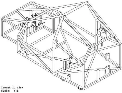
After examining the rules and regulation set for the chassis design, the final concept design for the new chassis was developed and modeled in 3D using CATIA V5R16 CAD software as shown in Figure 1 above. Mounting points for engine and suspension are also incorporated in the chassis design to better visualize on the car overall assembly. This helps to minimize the mismatch error between all the components and fasten the assembly process especially during the car fabrication and actual assembly stages later in this project.
3. MATERIAL SELECTION
As stated in the Perodua Eco-Challenge 2011 design regulations, only the chassis material is only allowed to be constructed from ferrous metals as the basic material. Thus, low carbon steel A36 was selected as the material for the chassis construction due to low cost, ease of manufacturing and good structural properties. Table 1 below shows in detail the material properties for the A36 low carbon steel.
Table 1. A36 low carbon steel material properties [3]
Material Property Value
Density (kg/m3) 7860
Ultimate tensile strength (MPa) 400 - 550
Yield strength (MPa) 250
Modulus of elasticity (GPa) 200
Poisson’s Ratio 0.266
Composition (%)
Carbon, C 0.26
Copper, Cu 0.20
Iron, Fe 99.0
Chromium, Cr -
Manganese, Mn 0.75
Phosphorous, P ≤ 0.040
Sulfur, S ≤ 0.050
4. CHASSIS STRUCTURAL ANALYSIS
In designing Perodua Eco Challenge car, there are three load cases that are required to be analysed to determine the car chassis rigidity, which is static bending, torsion and rollover condition. Finite element analysis using CATIA V5 Generative Structural Analsyis module was used to analyze the structural performance of the chassis. 3D geometry model of the chassis structure was also used in performing the analysis to enable better visualization of the final results.
design regulations is 450kg. While for rollover analysis, the maximum load is exerted on the upper chassis structure where the required value is four times the maximum car weight, which is approximately 18,000N as per stated in the Perodua Eco-Challenge 2011 design regulations Finally for the torsion analysis, the chassis torsional stiffness is determined by assuming that the weight distribution on the car is 40:60, due to the car is designed as a rear engine car with rear wheel drive, thus most of the car components will be located at the car rear section. Thus, the load exerted on the chassis rear section is approximately 1350N while for the front section, the load is approximately 900N. The torsional stiffness of the chassis is calculated using equation 1 below.
L y y
L F K
. 2
2 1 tan
.
1
(1)
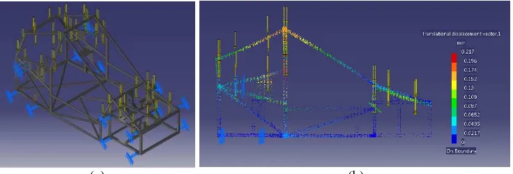
The results of the structural analysis are shown in Figure 6, Figure 7, and Figure 8 below. Table 2 summarized the results of the chassis performance in all three load cases.
(a) (b)
Fig. 6. (a) Location of load and constraints for bending analysis, (b) stress distribution result of the chassis bending analysis.
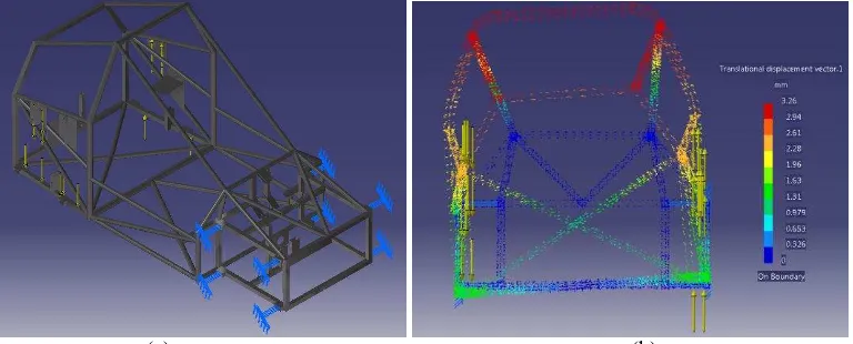
(a) (b)
(a) (b)
Fig. 8. (a) Location of load and constraint for torsional analysis at chassis rear side, (b) chassis displacement result of the torsional analysis at chassis rear side.
Table 2. Overall structural analysis results
Parameters Value
Front Rear
Chassis weight (kg) 54.3
Torsion Load (N) 900 1350
Bending Load (N) 4,500
Rollover Load 18,000
Yield strength (MPa) 250
Maximum von Mises stress due to bending (MPa) 19.9
Maximum roll over displacement (mm) 0.217
Factor of Safety Bending 12.56
Center length, L (mm) 300 425
Displacement y1 (mm) 0.102 0.91
Displacement y2 (mm) 0.098 0.94
Torsional stiffness, K (Nm/deg) 14,137.2 4,600.85 Torsional stiffness per weight ratio (Nm/deg.kg) 260.3 84.73
values shows that the chassis have acceptable torsional stiffness values such as suggested by Miliken and Miliken [4] where in design practice, the torsional stiffness recommended range is from 3000 lb-ft/deg (or 4068 Nm/deg) for small race car to 12,000 lb-ft/deg (or 16,272 Nm/deg) and above for a Formula 1 race car. The high value of torsional stiffness for both chassis is valuable to gain best handling performance when the value is high enough to be approximated as a rigid structure [5].
7. CONCLUSION
In conclusion, the new space frame chassis for UTeM Perodua Eco-Challenge car was was developed in this project. Finite element analysis was also used to determine the structural performance of the chassis for the intended application. Results of the analysis showed that the chassis structure is able to perform safely as per design requirement.
Acknowledgments
The authors would like to express sincere thanks to Faculty of Mechanical Engineering, Universiti Teknikal Malaysia Melaka for endless support throughout this project and special thanks to the crew members of the UTeM Perodua Eco Challenge 2011team.
References
[1] http://www.perodua.com.my/news-events/details/134, retrieved online on 25 August 2011.
[2] Rules and Regulation of Perodua Eco-Challenge 2011: version 1.5. Perodua Sdn. Bhd.
[3] Cambridge Engineering Selector (CES) EduPack 2010 software, Granta Design. [4] Miliken, W. F. and Miliken, D. L. (1995). Race Car Vehicle Dynamics,
Warrendale: Society of Automotive Engineers Inc., pp. 673-667.
![Table 1. A36 low carbon steel material properties [3]](https://thumb-ap.123doks.com/thumbv2/123dok/578712.68707/3.595.162.455.364.539/table-a-low-carbon-steel-material-properties.webp)