Vol 04, Issue 03; May-June 2013 International Journal of Engineering Sciences Research-IJESR
http://ijesr.in/
ISSN: 2230-8504; e-ISSN-2230-85122010-2013 - IJESR
Indexing in Process - EMBASE, EmCARE, Electronics & Communication Abstracts, SCIRUS, SPARC, GOOGLE Database, EBSCO, NewJour, Worldcat, DOAJ, and other major databases etc.,
864
Design, Analysis and Fabrication of Space Frame Chassis for
Amphibious Hybrid Vehicle
MUHAMMAD ZAHIR BIN HASSAN
1, MUHAMAAD NADZEER BIN ALEHAN
2,
MUHAMMAD FAHMI BIN MD ISA
3, MUHAMMAD ZAIDAN ABDUL MANAF
41Center of Advanced Research and Energy (CARE), Faculty of Mechanical Engineering, Universiti Teknikal
Malaysia Melaka.
1[email protected], 2[email protected], 3[email protected], 4[email protected]
ABSTRACT
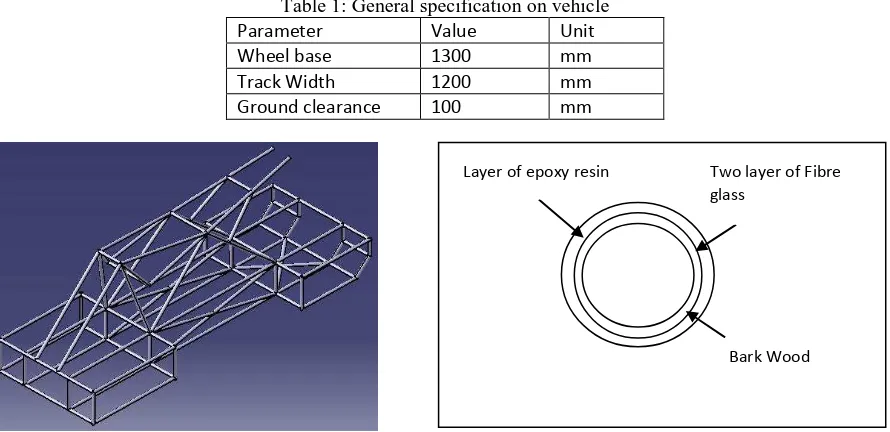
This paper explain the designed and development of space frame chassis for amphibious hybrid vehicle (AHV). Catia V5 R20 software is used for the designing and analysing before constructing the space frame chassis structure. Once the results of the analysis satisfied, the fabrication process is implemented. Hand lay-up method applied in the fabrication process of the chassis with the combination of bark wood, fibre glass E-class and epoxy resin. The general process involves in the fabrication process are cutting, drilling and fittings The chassis then assemble with brake system, drive shaft system, steering linkage system, suspension system and engine system. Good designs for manufacturing (DFM) practices have been implemented to assemble the chassis with all other AHV components.
Keywords: space frame chassis, amphibious hybrid vehicle.
1. INTRODUCTION
There are four type chassis are commonly used in automotive industry to build a vehicle which are space frame chassis, ladder frame chassis, backbone chassis and monocoque chassis.[1] Due to its strength, light weight and easy for maintenance, space frame chassis structure provide right answer and requirements needed to manufacture amphibious hybrid vehicle chassis.[2] Normally space frame chassis formed from the joining of cylindrical tube based on material used whether in triangle or square shape. Those tube are joined together to hold the engine load, steering linkage, power train system and suspension system. These chassis contained triangle geometrical shape which is better for the distribution of applied force to the chassis. [3] As a result, the chassis has strong structure. In development of the AHV, a light weight chassis will be the most important goal to achieve. A lightweight vehicle structure make the AHV accelerates faster. [3] Figure 1 showed the tension and compression force distribution on triangle geometrical shape. There are three nodes have in triangle geometrical shape. At blue point the force is applied where the strength of the structure depends on that point. Meanwhile, the red line showed the forced applied have distribute to all part of the structure. As a result, tension force is not at one point but to all point at chassis structure.
Figure 1: Tension and Compression Force on Triangle Geometrical Shape
2. DESIGN PROCESS
Vol 04, Issue 03; May-June 2013 International Journal of Engineering Sciences Research-IJESR
http://ijesr.in/
ISSN: 2230-8504; e-ISSN-2230-85122010-2013 - IJESR
Indexing in Process - EMBASE, EmCARE, Electronics & Communication Abstracts, SCIRUS, SPARC, GOOGLE Database, EBSCO, NewJour, Worldcat, DOAJ, and other major databases etc.,
In analysis stages, the model used the materials properties as tabulated in Table 2, 3 and 4 to conduct analyse the performance. The force applied to the vehicle 6278.4N which is the maximum load for the vehicle including the weight of the driver and passenger. The analysis consists of bending test on the chassis frame.
Table 2: Bark wood materials properties
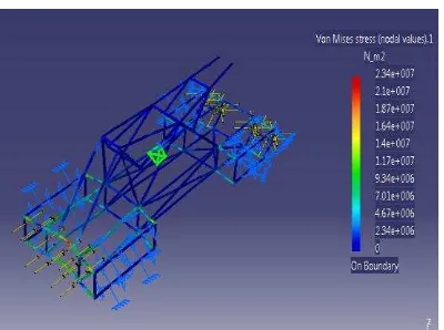
Figure 4 showed the results of analysis for bending test for space frame chassis model design. The analysis had been carried out using CATIA V5 software. In this analysis, the chassis is clamped at 8 point which is at the suspension system point and applied the force (maximum load) at front of the chassis. The factor of safety results are calculated based using equation (4) below and tabulated in Table 5.
Vol 04, Issue 03; May-June 2013 International Journal of Engineering Sciences Research-IJESR
http://ijesr.in/
ISSN: 2230-8504; e-ISSN-2230-85122010-2013 - IJESR
Indexing in Process - EMBASE, EmCARE, Electronics & Communication Abstracts, SCIRUS, SPARC, GOOGLE Database, EBSCO, NewJour, Worldcat, DOAJ, and other major databases etc.,
2
Figure 4: Bending Analysis for 3D Model Design
4. FABRICATION PROCESS
The design of the chassis is fabricated by using bark wood and chopped strand mat (CSM) fibreglass with 100 gsm thickness for lay-up process The process involved in these fabrication processes are joining, cutting, hands lay-up and sanding. Figure 5, Figure 6 and Figure 7 will summarise the chassis after fabricate and assemble with the vehicle components.
Figure 5: Joining Process of Chassis Fabrication Figure 6: Assembly Process in Space Frame Chassis
Figure 7: The Amphibious Hybrid Vehicle
CONCLUSION
The simulation and analysis have been done throughout Catia V5 R20 software and the factor of safety has been verified based on the load given. The fabrication of the chassis has successfully finished and tested by practicing design for manufacture (DFM). The fitting of the components have done according to the drawing with the tolerance of the measurement. The final product of the vehicle have been fabricate successfully.
ACKNOWLEDGEMENT
This work is supported by the University Teknikal Malaysia Melaka (UTeM) through Short-Term Project
PJP/2012/FKM(17C)/S01109 entitled “Development of Hybrid Amphibious Vehicle Propulsion System for
Marine and Rescue Operation”. This financial support is gratefully acknowledged.
REFERENCES
[1] J. W. Keith (2009). Introduction to Chassis Design. University of Newfoundland and Labrador.
[2] M. Howard (2000). Spaceframe: “A Study of an Emerging Body Construction technology”. University of
Bath
[3] B.J. Waterman (2011). Design and Construction of Space-frame Chassis. University of Western Australia
[4] Richard G.B., J.K. Nisbett.(2011), Shigley’s Mechanical Engineering Design (9th Edition).(pp. 247-249).