Design of Chassis Frame for All-Terrain Vehicle for Educational
Purposes
Muhammad Zahir Hassan
1, a,
Hendrie John
2,Fudhail Abdul Munir
2,b,
Mohd Azli Salim
2,c1Faculty of Engineering Technology, Universiti Teknikal Malaysia Melaka, Hang Tuah Jaya, 76100 Durian Tunggal Melaka, Malaysia
2Faculty of Mechanical Engineering, Universiti Teknikal Malaysia Melaka, Hang Tuah Jaya, 76100 Durian Tunggal Melaka, Malaysia
a[email protected], b[email protected], c[email protected]
Keywords: Chassis frame, All-terrain vehicle, Finite Element Analysis
Abstract. All-terrain vehicle is famously used for various purposes. The design of the chassis of this vehicle is critical in determining the overall strength. In this paper, the design chassis frame for the use of all-terrain vehicle (ATV) is presented. In designing the chassis frame, a proper design method was employed. Finite Element Analysis (FEA) was utilized to determine the maximum stress and displacement of the frame when a particular load is applied onto it. Structure modifications need to be done if the chassis frame could not sustain the applied load. After the design process is completed, the fabrication of the frame is conducted by students of the engineering faculty. The fabricated frame will be used as the main part for a project of which a complete ATV will be developed. The main purpose of the project is to instill the interest among the student in engineering through the application of classroom.
Introduction
All -terrain vehicles (ATV) have been widely used either by civilian or military [1, 2]. In some cases, there are ATV that has been used in agriculture field [3]. This type of vehicle is designed to operate in difficult and complex terrains [4, 5]. Generally, ATV is consists of three main parts. These parts are structure or better known as chassis, drive train and suspension. The main objective of this study is to develop a complete unit of ATV chassis frame, which is then used as the main part of an ATV. A proper design methodology is undertaken and students from engineering departments are involved in the project. Before the chassis frame is fabricated, basic Finite Element Analysis (FEA) were performed to determine the chassis frame feasibility. By participating in the project, students are able to have practical and hands-on experience particularly in automotive engineering field. Furthermore, students can also develop their much needed soft skills since they are working in a team to build the vehicle.
Design process
Conceptual design stage
In the process of developing the chassis frame, a proper design method is employed [6, 7]. The conceptual design is first developed using sketches. Then, Computer Aided
Design (CAD) software that is CATIA V5 is utilized to help the process of the design. Once the three dimensional (3D) drawing was completed, a basic Finite Element Analysis was performed. The analysis was done using built in function available in CATIA V5. It is important that the results of the analysis satisfy the technical requirement of the vehicle. Necessary modifications to the
Applied Mechanics and Materials Vol. 695 (2015) pp 742-745 Submitted: 05.09.2014 © (2015) Trans Tech Publications, Switzerland Revised: 10.09.2014 doi:10.4028/www.scientific.net/AMM.695.742 Accepted: 11.09.2014
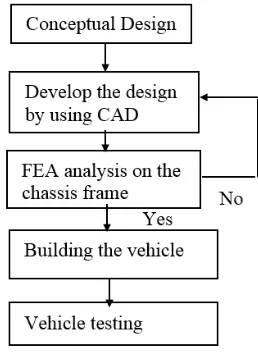
design need to be undergone if the analysis yields negative results. After all the process was completed, only then the fabrication of the frame was then conducted. All of these process stages are summarized in Fig 1 below.
Fig. 1 Design process flow chart
Meanwhile, sketches of the vehicle were produced at this stage to provide rough idea of chassis frame dimensions. Two types of conceptual design are suggested as shown both in Fig. 2 and Fig. 3.
Fig. 2 Sketch of Type-A vehicle
Fig. 3 Sketch of Type-B vehicle
The chassis frame should be designed to accommodate the required specifications as presented in Table 1 below.
Table 1 General technical specifications of the ATV [8]
Properties Value
Kerb weight 110 [kg]
Wheelbase 1.10 [m]
Width 0.82 [m]
Seat height from
the ground 0.68 [m]
Maximum power exerted from the
engine
5.2 [kW] @ 8500 [rpm]
As mentioned in the previous section, chassis frame is a vital part of the ATV. The frame should be designed in a way that it can sustain all the loads and operation conditions of the vehicle. Circular tube shape is used as the frame since it has higher bending stress compared to rectangular tube shape. A36 low carbon steel is selected as the material for the frame. The advantages of the low carbon steel is the high strength to weight value [9].
Computer-Aided-Design (CAD) stage
In this stage, the engineering drawing of the chassis frame is produced. Then, a simple finite element analysis was performed to determine the maximum stress and displacement of the chassis frame when a specific load is applied onto it. It is important to ensure that there will be no design failure occurs during operation of the vehicle. If the results of the analysis meet the technical requirement, only then the frame is fabricated. Structure static analysis was conducted by using CAE features available in CATIA V5R16. Loads are applied on the chassis frame area and the critical stresses that occur due to the load are analyzed. The factor of safety is then calculated using the obtained stress. Figure 4 shows frame before the static test was conducted. The value of the load applied on the frame is 2100 N.
Fig. 4 Three-dimensional (3D) chassis frame
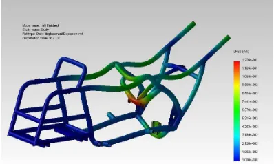
On the other hand, the Fig. 5 presents the contours of maximum displacement after the load is applied. The maximum displacement obtained is 0.012 mm. On the other hand, the maximum stress obtained from the analysis is 116.7 MPa.
Fig. 5 Contours of maximum displacement when load is applied
By using this value, the calculated factor of safety (F.O.S) is 2.13. This value is deemed sufficient for the chassis frame. Since these results satisfy the requirement, the fabrication of the chassis frame is then conducted.
Conclusions
In this paper, the method of designing chassis frame for the use of all-terrain-vehicle is successfully demonstrated. Finite Element Analysis (FEA) results show that the designed chassis can withstand the given applied load. Since the results of the analysis are within the accepted limits, the fabrication of the chassis is conducted. This chassis will then be used as the main part of the designed ATV for educational purpose.
References
[1]. D.Nagarjuna, J. M. Farooq, A.S.N.Saiteja, P. S. S. Teja, Optimization of Chassis of an All Terrain Vehicle, International Journal of Innovative Technology and Exploring Engineering, Vol. 2, (2) (2013) 55-57.
[2]. G. H. Hohl, Military terrain vehicles, Journal of Terramechanics, Vol. 44 n.1 (2007) 23-34. [3]. S. Milosavljevic, F. Bergman, B. Rehn, A. B. Carman, All-terrain vehicle use in agriculture:
Exposure to whole body vibration and mechanical shock, Applied ergonomics, Vol. 41, n. 4 (2010) 530-535.
[4]. K. Chaudhari, A. Joshi, R. Kunte, K. Nair, Design And Development Of Roll Cage For An All-Terrain Vehicle, International Journal on Theoretical and Applied Research in Mechanical Engineering, Vol. 2, n. 4 (2013) 49-54.
[5]. J. Pijuan, M. Comellas, M. Nogués, J. Roca, X. Potau, Active bogies and chassis levelling for a vehicle operating in rough terrain, Journal of Terramechanics, Vol. 49, n. 3-4 (2012) 161-171.
[6]. F. A. Munir, M. I. M. Azmi, M. A. Salim, M. R. M. Zin, M. Z. Hassan, Preliminary Design of Carbon Composite Facing for Dry Clutch Disc of Mini Agricultural Tractor, International Review of Mechanical Engineering (IREME), Vol. 5, n.4 (2011) 577-580.
[7]. V. A. W. Hillier, Fundamentals of Motor Vehicle Technology, Nelson Thornes, 2004.
[8] J.J. Dawkins, D. M. Bevly, R. L. Jackson, Evaluation of fractal terrain model for vehicle dynamic simulations, Journal of Terramechanics, Vol. 49 (2012) 299–307.
[9]. K.-H. Dietsche; M. Klingebiel (Ed.)^(Eds.), Automotive Handbook, Robert Bosch GmbH (Wiley), Germany, 2007.

![Table 1 General technical specifications of the ATV [8]](https://thumb-ap.123doks.com/thumbv2/123dok/485107.53238/3.595.204.393.514.648/table-general-technical-specifications-atv.webp)
