FEM ANALYSIS AND IMPROVE DESIGN OF FRONTAL BUMPER OF WIRA
MOHD FIRDAUS BIN MAT NOR
We hereby declare that we have read this work and in my opinion this work
is sufficient in term of scope and quality to bestowal Bachelor of Mechanical Engineering (Automotive)
Signature : ………
Supervisor’s Name 1 : ..………..
Date : ………
Signature : ………
Supervisor’s Name 2 : ..………..
FEM ANALYSIS AND IMPROVE DESIGN OF FRONTAL BUMPER OF WIRA
MOHD FIRDAUS BIN MAT NOR
The PSM (Projek Sarjana Muda) report is considered as one of the essential for students to complete their bachelor program in Mechanical (Automotive)
Faculty of Mechanical
Universiti Teknikal Malaysia Melaka
“I declared that this thesis is the result of my own work except the ideas and summaries which I have clarified their sources”
Signed :
iii
iii
ACKNOWLEDGEMENT
Alhamdulillah…Thanks to Allah The Almighty because finally I have complete my PSM1 to fulfill the requirement of Mechanical Engineering Faculty to graduate as Bachelor in Mechanical Engineering. Firstly, I would like to express my thanks to my dedicated advisor, Mr Nor Azmmi B Masripan, for his commitment, guidance and credibility in the preparation stage of this report. His cooperation and advice help me to prepare a well-prepared report at last.
ABSTRACT
v
ABSTRAK
TABLE OF CONTENTS
CHAPTER CONTENTS PAGE
DECLARATION ii
ACKNOWLEDGEMENT iii
ABSTRACT iv
ABSTRAK v
TABLE OF CONTENTS vi
LIST OF TABLES ix
LIST OF FIGURES xv
LIST OF ABBREVIATIONS xvi
LIST OF APPENDIX xvii
CHAPTER I INTRODUCTION 1
1.1 Problem Statement 3
1.2 Objective 4
1.3 Scope of The Project 4
1.4 Outline of the Thesis 5
CHAPTER II BACKGROUND THEORY 2.1 Car Bumper 6
2.1.1 History and Usage 6
2.1.2 Bumper Design and Finite Element 7
vii
CHAPTER CONTENTS PAGE
2.2 Impact Test 9
2.2.1 Type of Impact Test 9
2.2.1.1Frontal Impact Test 9
2.2.1.2Side Impact Test 10
2.2.1.3Pedestrian Impact Test 11
2.2.2 Safety 11
2.2.3 Analysis In Impact Test. 12
2.3 Finite Element Method 17
2.3.1 Meshing 18
2.3.1.1 Plane Stress Finite Element Mesh 18
2.3.1.2 Plane Strain Finite Element Mesh 19
2.3.1.3 Axisymmetric Finite Element Mesh 20
2.3.1.4 Nodes and Element 20
2.3.2 Type of Element in FEM 22
2.3.2.1 Plate Element 23
2.3.2.2 Shell Element 24
2.3.2.3 Solid Element 24
2.3.3 Theory of Finite Element Analysis 26
2.4 Honeycomb structure as the Impact energy absorption system for vehicles 35
2.4.1 Finite Element Analysis of Impact Damage Honeycomb Sandwich 36
CHAPTER III METHODOLOGY 3.1 Introduction 42
3.2 Decide the Effect of Static Load to frontal bumper 42
of Proton Wira. 3.3 3D-Modelling of Wira bumper. 43
3.4 Finite Element Analysis 45
3.4.1 Simplifications and Assumptions in the Analysis 45
CHAPTER CONTENTS PAGE
3.5 Modification Analysis 50
CHAPTER IV RESULTS AND DISCUSSION 4.1 Analysis Result and Discussion 4.1.1 Result of the First Impact Situation 53
4.1.2 Result of the Second Impact Situation 59
4.1.3 Result of the First Impact Situation to the smaller size of the honeycomb structure. 64
CHAPTER V CONCLUSION AND RECOMMENDATION 5.1 Conclusion 67
5.2 Recommendation 68
REFERENCES 69
x
LIST OF FIGURES
FIGURE TITLE PAGE
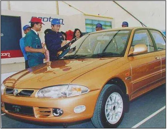
Figure 1.0 The lunching proton Wira first model 2 (Source: Proton Wira Wikipedia)
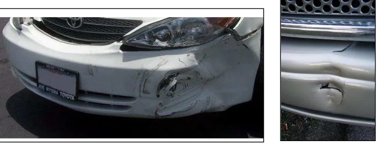
Figure 1.1 Example low speed collision impact 3 (Source: www.crashcar.com)
Figure 2.0 Basic Feature of Car Bumper 7 (Source: www.unipres.com)
Figure 2.1 Frontal Impact Test 10 (Source: www.impacttest.com)
Figure 2.2 Side Impact Test 10 (Source: www.impacttest.com)
Figure 2.3 Pedestrian Impact Test 11 (Source: www.impacttest.com)
Figure 2.4 Test Setup 13 (Source: Willem, (2000))
FIGURE TITLE PAGE
Figure 2.6 Comparison deformation modes 14 (Source: Willem, (2000))
Figure 2.7 BMC damage 15 (Source: Willem, (2000))
Figure 2.8 Validation of two layer panel 15 (Source: Willem, (2000))
Figure 2.9 Simulated leg impacts 16 (Source: Willem, (2000))
Figure 2.10 (a) truss structure; (b) two-dimensional planar 18 (Source: www.finite_element_method.com)
Figure 2.11 Plane stress meshing 19 (Source: www.solidmechanic.com)
Figure 2.12 Plane strain meshing 19 (Source: www.solidmechanic.com)
Figure 2.13 Axisymmetric meshing 20 (Source: www.solidmechanic.com)
Figure 2.14 Element and node 21 (Source: www.solidmechanic.com)
Figure 2.15 Element 22 (Source: www.solidmechanic.com)
xii
FIGURE TITLE PAGE
Figure 2.17 Shell Element 24 (Source: Vermolen, (2005))
Figure 2.18 Solid Element 25 (Source: Vermolen, (2005))
Figure 2.19 Three-member truss 26 (Source: www.eng.vt.edu.com)
Figure 2.20 Single truss member 27 (Source: www.eng.vt.edu.com)
Figure 2.21 Matrix 28 (Source: www.eng.vt.edu.com)
Figure 2.22 Matrix 1 28 (Source: www.eng.vt.edu.com)
Figure 2.23 Element 29 (Source: www.eng.vt.edu.com)
Figure 2.24 Matrix 2 29 (Source: www.eng.vt.edu.com)
Figure 2.25 Stiffness matrix 29 (Source: www.eng.vt.edu.com)
Figure 2.26 Stiffness matrix 1 30 (Source: www.eng.vt.edu.com)
FIGURE TITLE PAGE
Figure 2.28 Displacement and external force 31 (Source: www.eng.vt.edu.com)
Figure 2.29 Equilibrium 32 (Source: www.eng.vt.edu.com)
Figure 2.30 Matrix of external force 33 (Source: www.eng.vt.edu.com)
Figure 2.31 Matrix 3 33 (Source: www.eng.vt.edu.com)
Figure 2.32 Matrix 4 34 (Source: www.eng.vt.edu.com)
Figure 2.33 Bees honeycomb 35
(Source: www.ipbase.com)
Figure 2.34 Honeycomb crushing due to a deformable body impact. 37 (Source: D.P.W. Horrigan (1998))
Figure 2.35 Nominal Stress-Strain behaviour of Nomex TM core 38 (Source: D.P.W. Horrigan (1998))
Figure 2.36 Finite element model. 39
(Source: D.P.W. Horrigan (1998))
Figure 2.37 Soft impact model response steps 1 to 4 40
(Source: D.P.W. Horrigan (1998))
xiv
FIGURE TITLE PAGE
Figure 3.0 3D-Modeling of the Ordinary Wira bumper 43
Figure 3.1 Model cross section and sweep path 44
Figure 3.2 Meshing 46
Figure 3.3 Load and Boundary conditions 47
Figure 3.4 Load and Boundary conditions 48
Figure 3.5: Wira frontal bumper with simple back structure 50
Figure 3.6: Wira frontal bumper with honeycomb back structure 51
Figure 3.7: Flowchart of the project 52
Figure 4.0: Out of plane Displacement and Von Mises stress
during the impact to the Ordinary Wira frontal bumper 54
Figure 4.1: Out of plane Displacement and Von Mises stress during impact to the Wira bumper with simple back structure. 55
Figure 4.2: Out of plane Displacement and Von Mises stress during the impact to theWira bumper with
Honeycomb back structure. 56
Figure 4.3: Max. Out of Plane displacement of the
First impact situation 57
FIGURE TITLE PAGE
Figure 4.5: Out of plane Displacement and Von Mises stress
during the impact to the Wira ordinary bumper. 59
Figure 4.6: Out of plane Displacement and Von Mises stress during the impact to the Wira bumper with simple
back structure. 60
Figure 4.7: Out of plane Displacement and Von Mises stress during the impact to theWira bumper with
Honeycomb back structure. 61
Figure 4.8: Max. Out of plane displacement of the
Second impact situation 62
Figure 4.9: Max Von mises stress of the Second impact situation 63
Figure 4.10: Out of plane Displacement and Von Mises stress during the impact to theWira bumper with smaller
Honeycomb back structure. 64
Figure 4.11: Max. Out of plane displacement of difference
size honeycomb structure 65
Figure 4.12: Max. Von mises stress of difference
ix
LIST OF TABLE
NO. TITLE PAGE
2.0 Honeycomb continuum damage model parameters. 41
2.1 Damage comparison for a normal impact velocity of 27.9 ms-1. 42
4.0 First Impact Situation 58
4.1 Second Impact Situation 63
4.2 First impact situation on different size of honeycomb structure 66
1.0 Gantt Chart PSM1 70
LIST OF ABBREVIATIONS
A = Acceleration M = Mass
KIC = Fracture Toughness of material Gc = The fracture energy per unit area E = Young Modulus
ν = Poison ratio
γ = The surface or fracture energy mph = Mile per hour
L = Length R = Rotation
Sf = Fatigue strength α = Alpha
Se = Endurance limit
Sut = Ultimate tensile strength F = Force
K = Spring stiffness x = Displacement
Ym = Yield stress of the material
VM = Von Misses stress
xvii
LIST OF APPENDIX
NO TITLE PAGE
CHAPTER 1
INTRODUCTION
PROTON produced Malaysia's first car, the Proton SAGA, commercially launched on July 9, 1985 by Malaysian Prime Minister, Dato' Seri Dr. Mahathir Mohamad, who had originally conceived the idea of a Malaysian car. After that more model were come out especially Wira. Wira was the popular model among car user in Malaysia rather than Saga, Iswara and other model. The Proton Wira model was first introduced in 1993 as a 4-door saloon and was based on the 1992 Mitsubishi Lancer design, but the styling was slightly modified to distinguish it from the Lancer. “According to Proton Wira Wikipedia (2007), modifications include headlights from the 1992 Mitsubishi Colt, tail lights from the 1987 Mitsubishi Gallant hatchback, bumpers from the Mitsubishi Mirage and a different dashboard. The frontal design continues the styling first shown on the Proton Iswara with a fluted bonnet that tapers towards the Proton badge on the grill.
2 In the same year, exports to the United Kingdom began where it was marketed as the Persona (not to be confused with the latest 2007 sedan model by Proton). As with the Saga, all export models used multi-point fuel injection to comply with the Euro I emissions standards. The multi-point injection versions were badged as MPi, although this was only used on the engine, and never on the trim levels (unlike 1.5 MPi GLS in the previous car, the Saga, the trim levels were simply 1.5 GLS etc.).A minor facelift was introduced in 1995 with a new grille and slimmer tail lights with clear indicators.
In 1995, the Mitsubishi 4G13 1.3-litre 12-valve engine also used in the Saga was introduced for the Wira. This was followed in 1996 by the 133bhp 1.8L 16-valve DOHC engine with multi-point fuel injection. At the same time, a 2.0-litre diesel-powered variant (badge as SDi in some markets) was also offered but was later phased out in later years due to lack of interest from consumers. From 1998, all engine options for the Wira in Malaysian market were fuel-injected and carbureted models were phased out. “According to Proton Wira Wikipedia (2007), In 2000 the Wira received various improvements to reduce its NVH (noise, vibration and harshness) through additional insulation and suspension tuning from Lotus. In the same year, the Wira name was used in the United Kingdom”.
1.1 Problem Statement
Since it was produce in 1993 until now there lot of changes had been made by Proton to suit their customer need especially for the engine performance, electrical and electronic system. Unfortunate there is nothing been change through its body, especially its frontal bumper. There is lot of problem since to appear involving the Wira frontal bumper failure that causing lot of problem to the customer recently. As a low-speed collision occurs, such as when a driver accidentally crashes his car into a side walk pole or another car behind, the bumper is permanently dented. This was creating an adding cost to the customer to replace it with a new one. A car bumper is a very complex component for the car, it job was to absorb the impact under low-speed collision for the safety of the passenger. But sometimes, because of unsuitable design the bumper was hardly damage with a small impact on it. This bumper must be analyze back to find out it structure strength so that it can be redesign back to overcome this problem.
4
1.2 Objective
The main objective of the project is to analyze the effect on Wira frontal bumper under static load and to make an improvement on the design. This analyze was conduct under low-speed collision impact, to come up with a result of any changing characteristic of the bumper. The damage of the bumper surface will be investigate in term of design failure and Static load is the best features in this project because it will definitely show how the bumper condition reacts with the force given clearly. It is hoped that by performing this project, few justifications could be make on the bumper failure phenomenon. Lastly; this project also hopes to come up with any solution that can be carried out to minimize the problem of this Wira bumper especially toward its design.
1.3 Scope
Since for this research, it is focusing on analysis, simulation and modeling of frontal bumper of Wira using this Finite Element Method (FEM). The Finite Element Method will be used to predict out of plane displacement and von mises stress of the bumper during the collision under the specified load. This is to find the any lack of stiffness or the elastic of the bumper using the static load as the force medium. In this project the CATIA software will be used to make a 3D modeling of Wira frontal bumper, this software was used because it can create the best feature of real frontal Bumper Wira.
1.4 Outline of the Thesis