International Journal of Engineering Trends and Technology (IJETT) – Volume 4 Issue 5- May 2013
ISSN: 2231-5381
http://www.ijettjournal.org
Page 1768
Structure Analysis of Cast Iron for Dry Clutch of
Amphibious Vehicle
Muhammad Zahir Bin Hassan1, Muhammad Fahmi Bin Md Isa2, Muhamaad Razil Razali3, Muhammad Zaidan Abdul Manaf4
1
Center of Advanced Research and Energy (CARE), Faculty of Mechanical Engineering, Universiti Teknikal Malaysia Melaka. minimum in weight. Finite element analysis is use to predict the maximum stress can be apply to the disc. The fabrication process is conduct using a conventional milling machine.
Keywords— cast iron clutch disc, finite element analysis.
I. INTRODUCTION disc braking system consists of many parts such as friction pad, master cylinder, wheel cylinder and
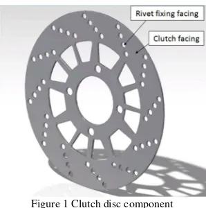
Clutch disc is design so it can be grip tightly by pad lining in the calliper. Clutch disc can be divided into two components such as, clutch facing and rivet fixing facing as shown in the Figure 1.
II. DETERMINE PARAMETER
The capabilities of braking system performance were depend on its design. The design process of
displacement deformation of clutch and the maximum load that clutch can withstand.
There are also several criteria need to be considering in designing a clutch disc such as:
i. Material selection
i. The applied pressure to the disc is uniform. ii. Disc is completely been contact.
This assumption is made to determine the maximum stress can be applied to the selection material clutch disc. In addition it helps to determine the parameter of clutch disc such as optimum diameter in finite element analysis.
A. Justifying Maximum Torque Transmitted
International Journal of Engineering Trends and Technology (IJETT) – Volume 4 Issue 5- May 2013
ISSN: 2231-5381
http://www.ijettjournal.org
Page 1769
the automotive application. Clutch disc diameter is be justified by assume:
i. Pressure applied are uniformly ii. Factor of safety (FOS) is 1.5
iii. Lining pad material is woven asbestos. iv. Coefficient of friction is set to f = 0.15
v. Maximum pressure applied onto clutch,
Pmax= 682kPa
Outer radius clutch disc ro 220mm
Using
To calculate the axial force, equation (2) is used
Fa = πPmax Di (Do-Di) (2)
where:
D0 = Outer Diameter
Di = Inner Diameter
Figure 2 Direction of Axial force of clutch facing.
Hence, the result for maximum allowable torque and axial force is show in Table II.
TABLE II
Clutch disc geometrical properties Properties Value
Maximum value of torque T 59.43 Nm
Axial Force Fa 10067.0811 N present analysis are shown in the Table III.
TABLE III
Properties of cast iron clutch disc. Properties Value
Young modulus 1.1x10¹¹ Nm-2
Poisson ratio 0.28
Density 7200 kgm-3
Thermal expansion 1.1x10⁻⁵ K.deg
Tensile ultimate Strength 2.4x10⁸ Nm-2
Compressive ultimate strength
8.24x10⁸ Nm-2
International Journal of Engineering Trends and Technology (IJETT) – Volume 4 Issue 5- May 2013
ISSN: 2231-5381
http://www.ijettjournal.org
Page 1770
Fig. 3 Meshing model.
The result in finite element analysis was determined and the total deformation is shown in Figure 4. The maximum total deformation is 1.0377x10⁻⁵ mm. Since the gap between clutch disc and pad lining is greater than maximum total deformation. Thus, it is acceptable.
Fig. 4 Total deformation of clutch facing.
The maximum von misses stress is 0.034286 MPa and the minimum von misses stress is 5.24x10⁻⁶ MPa. Both of these results were shown in Figure 5. It shows that the maximum stress will be exert on the four hole that mounted to the wheel hub. Since the result maximum Von-mises stress from finite element analysis is greater than the yield strength of
the cast iron, there will be a wear and tear in long period.
Fig. 5 Von-mises stress of clutch facing.
III.FABRICATIONPROCESS
Fabrication process was conducted after the finite element analysis using conventional milling machine as shown in Figure 6. The subject was clamp tightly so there is no slipping during drilling process. In these process four holes was drilled on the clutch disc carefully with tolerance ±0.001mm. These four holes will be used as mounted for clutch disc to the wheel hub in the experimental analysis.
International Journal of Engineering Trends and Technology (IJETT) – Volume 4 Issue 5- May 2013
ISSN: 2231-5381
http://www.ijettjournal.org
Page 1771
IV.CONCLUSIONS
This paper explains about the structure analysis of cast iron clutch disc. The clutch disc will be test in amphibious vehicle for experimental analysis to determine its durability. The result of this paper will be used for the future study in automotive application.
REFERENCES
[1] Sivarao, M. Amarnath, M.S.Rizal, A.Kamely (1990), An Investigation Toward Economical Brake Lining Wear Alert System, International Journal of Engineering & Technology IJET Vol.9 No9. [2] Jin-Le Zhang, Biao Ma, Ying –Feng Zhang and He Yan Li (2009): Simulation and Experimental Studies on the Temperature Field of a Wet Shift Clutch during one Engagement, in: International Conference of Computational Intelligence and Software Eng, (CiSE) 2009 IEEE, 11-13.12.2009, pp.1-5.