DEVELOPMENT OF MOTION CONTROL USER INTERFACE FOR XV TABLE
R. NUR AIDAWATY
Paper Presented at the International Conference on Engineering and ICT (ICEI 2007), 27 -28 Nov 2007, Hotel Equatorial Melaka.
11
11
DEVELOPMENT OF MOTION CONTROL USER INTERFACE FOR XV TABLE
R. NUR AIDAWATY
Paper Presented at the International Conference on Engineering and ICT (ICEI 2007), 27 -28 Nov 2007, Hotel Equatorial Melaka.
UNIVERSITI TEKNIKAL MALAYSIA MELAKA
Development of Motion Control User
Interface for XY Table
T. Zahari1,
R.Nur Aidawaty
2,A. Shariman
2,A.R. Muhammad Arfauz2
Abstract - An XY table is an equipment which is widely used in industry for automation application. Examples of its application include CNC machining, laser welding, milling and etc. An XY table is controlled by a motion control system consists of the control of software and hardware such as a PLC. In this study an
XY table is used to position the focus head to automate the welding process for laser spot welding. A program has been developed to control the XY table. The performance of the XY table for linear and circular interpolation was analyzed. A user interface was also developed to read CAD data file and transform it into XY movement. The user interface is developed using Visual Basic for manual and automatic positioning.
Keywords - Automation, Control Systems, Motion Control
I. INTRODUCTION
The most common type of robots used is a gantry robot. A gantry robot is also known as a Cartesian coordinate robot or X-Y-Z robots. A gantry robot is generally an automatically controlled, reprogrammable, multipurpose manipulator programmable in three axes. It consists of a tool axis and work piece table. The tool axis is more often to be programmed with the height adjustable with respect to the shape of the work piece. The work piece table is normally known as an XY table which has two axes. It moves in specified direction and distance.
An XY table is needed for a laser welding system. The system consists of an Nd:YAG laser generator, programmer control panel with a RS232 link, a flexible fibre optic for laser delivery, and a focus head. In order to automate the welding process, there is a need for a system to position the focus head.
An XY table linked with a programmable controller is proposed.
This work was financially supported by Universiti Teknikal Malaysia Melaka, Malaysia under Grant PJP/2006/ fkp(5)-Sl85.
1
The author is with the Faculty of Engineering, Universiti Malaya, KL, Malaysia (e-mail: zahari taha(<l.>um. edu.my)
2
The authors are with the Faculty of Manufacturing Engineering, Universiti Teknikal Malaysia Melaka, Malaysia (e-mail: [email protected])
The objective of this research is to develop a user interface for programming the motion of an XY table. The scope of work is the controller can be accessible via Visual Basic commands. A user interface will be developed to allow user to program Point-To-Point and circular movement without having to write the program. A path has to be generated from CAD data to be transformed into linear axes movement
Until recently, scientist and engineer controlled motion systems using PLCs. These system were reliable but difficult to program and generally limited in performance. The PC based approach is more flexible and provide better performance. Controller or control board is a brain that directs all movement. Before selecting the necessary controller, one must know the required task and features. Motion controllers range from low end to high end. Low-end motion controllers are normally simple. It consists of motion of motor from one position to another, less expensive and does not have many features . High-end controllers work better for more involved applications because this type offers their own set of special features. This type can provide different ranges of motion profiles, such as linear interpolation and contouring.
There are two fundamental motion tasks, which are used in modern mechanical system
[l]:-1) Point-to-point (PTP) movement for moving from one position point to another (positioning)
2) Continuos-Path (CP) movement for moving along a prescribed position trajectory (tracking)
The structure of programming and control can be divided into two parts [3] which
are:-1) Basic operation
2) Advance operation ofXY positioning mechanism
Basic operation design includes USER, READ, and DRAW while advanced operation includes utilizing the webcam for image acquisition.
International Co nference on Engineering and !CT (ICE! 2007)
Poslion (p) Axis 0
Axis 1
Axis 2
Axis 3
COOl)al'e Polrts
AxisO
Speed(pps)
Axis O
Axis1
Axis 2
Axis 3
Command OulpY AxisO
Axis 1
00 Status (Hex) O servoon Axis 0
Axis 1
I
PTPI {
Zセ セZ@
__
.d ____ 10 Use Trigger? L. __ Q⦅sサjHjエIセ G@
Axis 2
Axis 3
Lne X-Y j {
{⦅ ᄋZN M Zセ セ M[@
Axis 1
Motion Status
AxisO
Axis 1
Axis 2
{ッNュ|
ヲ セ セ@
Axis3
Reset Position
EJ
IY1anua!Control - X axis
G
Set the Speed (1000-20CXl0)8
10008
p:>Stion display
セbb@
0RecordposiionCoorcina!es :
Fig. 2. User Interface for motion control
research, the compensators are applied as C programs running on an embedded processor.
II. METHODOLOGY
The aim of this research is where a user interface for controlling the motion of XY table will be developed which consists of manual and automatic positioning from CAD data file at the end of this research.
Firstly, the design of XY table is studied and identified in term of its mechanical structure. After that, the motion controller for XY table is studied and prepared. The preparation of motion controller depends on the specification of motor used. A motion controller is used to positioning the tool by controlling the servo motor of the X-axis and Y-axis. The motion is developed by using Visual Basic commands. By using the interface, the path for CAD data will be generated to provide non-written programming to place the tool at the target position.
III. DEVELOPMENT OF MOTION CONTROLLER USER INTERFACE
For the XY table section, the movement of the axes is controlled by a motion controller card that is slotted inside the computer CPU. The card could be programmed with programming language to drive pulse train input servo motors via pulse generator into desired motion profile. The card has sensor/encoder inputs.
The motion control of XY table consists of AC servomotor, servomotor driver, motion controller card,
356
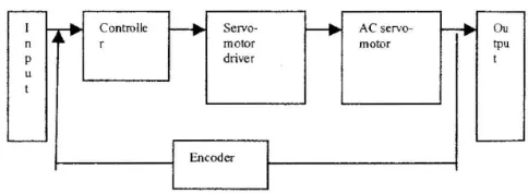
encoder and the programming software. Generally, the design for one axis is shown as Figure 1.
Contro lle
Servo-motor
dri ver
Encoder
AC
servo-motor
Fig. 1. Block Diagram of motion control system
tpu t
Figure I shows the input is the data from the user in term of CAD data file or manual positioning. The data is analyzed by controller. The controller is a motion control card consists of functions specifically for motion such as linear and circular interpolation movement. The programming software is Visual Basic where will translate and send the signal in pulse width modulation (PWM) to the servomotor driver. With specified gain, the -signal is sent to the servomotor to run the application. During the operation, the encoder gives feedback on the position of the XY axes.
The user interface provides the user to key in values for motion control in two ways which are manual or automatic positioning. Figure 2 shows the user interface developed for motion control of XY table. Figure 3 illustrates the control flow of the user interface system .
[image:4.597.77.503.67.315.2] [image:4.597.314.556.394.483.2]User Controller Motor x interface card
function y
Feedback x
encoder
Fig. 3. Control flow of the user interface
A user will key in the values or uploading the CAD files for positioning in linear or circular interpolation. The position of the XY axis that has to be entered is in pulses. Therefore, for manual positioning such as point-to-point positioning, the distances from original position have to be multiplied by 200 pulses/mm. This is due to the resolution of encoder (1000 pulses) and the resolution of gear mechanism (5 mm/ revolution).
For automatic positioning, the user is required to upload the CAD drawing from file/document folder. Figure 4 shows the steps to be followed to upload the file.
Draw linear/ circular
User choose Play button to
run the
application
Save the file in DXF file format
( * .dxt)
Save the DXF file in wordp ad
(* hct)
Display the coordinate and other parameter for r.nntrnlln
Programming will calculate the displacement in pulses/mm and send the signal to the motor
Uplo ad the file BMMセセ@ Programming read the file
Fig, 4. Uploading File Procedure by User
IV. RESPONSE OF THE XY TABLE
Figure 5 to Figure 8 shows the position, speed and acceleration ofX axis for linear interpolation.
120 100 80 ';: Mセ@ 60 40
I
20line_xy
I o
l⦅⦅⦅⦅⦅⦅ッセセMQPセセRMッセM。セZMセセセNLMMMTMPセセUPセセVMPセ@
Fig. 5. XY positioning for Linear Interpolation
120
セ@ 100
E
g 80
l5 60
""
Ui 400
Q. 20
0
0 2
Control Instrumentation and Automation
position_axisO
4
time(s)
6 8
Fig. 6. Position ofX Axis (increment vs time)
25 20 15 10 2 axisO _speed
3 4 6
time(s)
Fig. 7. Speed ofX Axis (increment/s vs time)
acceleration 0.15 0.1 0.05 0 -0.05 -0.1 -0.15 -0.2 -0.25 time(s)
Fig. 8. Acceleration ofX Axis (increment/s2 vs time)
For X axis trajectory generation, the position started from zero and ended at 100 mm. However in between times, t is 0 s to 1 s and time, t is 5s to 6s, there is a nonlinear graphs. This happens where the axis is started to accelerate at 0.1 mm/s2 to re-ach a constant speed at 22.5 mm/s. When the axis towards the end, it started to decelerate at 0.2 mm/s2 until it stops at time, tis 6s.
Y Axis trajectory generation for Linear Interpolation
[image:5.603.39.260.74.146.2] [image:5.603.319.534.78.516.2] [image:5.603.28.277.333.548.2] [image:5.603.50.241.627.748.2]International Conference on Engineering and JCT (ICE! 2007)
60
50 40 30
20
10 0
position_axis1
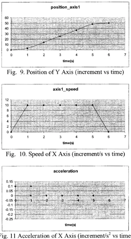
Fig. 9. Position ofY Axis (increment vs time)
axis1_speed
time(sj
Fig. 10. Speed ofX Axis (increment/s vs time)
acceleration
0.1
0.05
0
--0.05
-0.1
--0.15
-0.2
--0.25
time(sj
Fig. 11 Acceleration of X Axis (increment/s2 vs time)
For Y axis trajectory generation, the position started from zero and ended at 50 mm. According to figure shows above in between time, t is 0 s to 1 s and time, t is 5s to 6s, and there are nonlinear graphs. This is because the axis is started to accelerate at 0.1 mm/s2 to reach a constant speed at 22.5 mrn/s. When the axis towards the end, it started to decelerate at 0.2 mm/s2 until it stops at time, t is 6s.
Figure 12 to 14 shows the pos1t10n, speed and acceleration of X axis for linear interpolation as shown in Figure 1 l.
セセセセセセセ セセセM
axis1
Fig. 11. XY positioning for Circular Interpolation
358
According to the Figure 11 shows above, the circular interpolation involves two axes. The axis 0 which is X axis moved positively from 0 mm to 100 mm and bak to Omm again. In contrast, the axis l which is Y axis moved first in negative direction and after that positive direction and back to negative direction. The position movement by Y axis is from 0 mm and back to 0 mm.
X Axis trajectory curve for Circular interpolation
position_axisO
セZ セG@ セセᄋ
ᄋᄋᄋ M
Mᄋᄋᄋ MM
ᄋ@
i
i セ セセセセ@
·20 . .. -·· - 2 . - -4 . .. ... 6 ... . .. ... 8 . .. --·· -10-- -. - . 1-2 ... .. l4i
! time(s)
J
Fig. 12. Position of X Axis (increment vs time)
velocity
30
RP KM セMMilM セ セMMBM]Mセセセ セセセセセセ GMMMG@
Fig. 13. Speed ofX Axis (increment per sec vs time)
acceleration axis O
40
セ@ セセ Nセセセ セセセセセセセセセ セMNKM MMG@
セ@ セ セZセセセセ セセセセセセセセ MAGM セセ@
E I
セ@ QPKMMセ JM セセセセセセセセ セエャMM セ セ@
.2
セ@ P KMセセセMNM セMMNM セ MMLMセMWG BGM セ セセ@
セ@ M
セ@ -10
-20
time (s)
Fig. 14. Acceleration ofX.Axis (increment per sec2 vs time)
For X axis trajectory generation, the position started from zero and ended at 0 mm. At first, the axis moved positively to 100 mm and decelerated parabolically where it started from about 33mm/s2 to -l 2rnrn/s2
. At time, t = 6s,
the axis started to turn to negative direction to reach 0 mm at the end. Thus, the axis has accelerated parabolically from about -12 mm/s2 to 33 mm/s2
• The speed of axis is not
constant where it started at -21 mm/s and increased until 28 mis at time, t
=
3s where the position is near 50 mm. It turns to decrease until -28mis
at time, t=
10s where the position is 20 mm . After that, it increases until the axis stop at position Omm. [image:6.598.50.260.69.453.2] [image:6.598.323.536.178.621.2] [image:6.598.61.247.594.728.2]y
Axis trajectory curve for Circular interpolationfigure 15 to 17 shows the position, speed and acceleration of X axis for linear interpolation.
position_axis1
Z イMセMᄋM
ᄋ@ MMセM
ᄋ@
-G Z セ
ᄋ@ オ セ@
• • • •M キ イセ
l M l@
..
111.u" -- 1'
l
i セセ@ -- - - -__ - - --- - - --- --_- -- - - :
time(s)
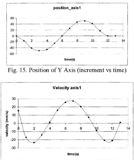
Fig. 15. Position of Y Axis (increment vs time)
Velocity axis1
30
r
---セMKMMMセセ セセセ MMLlM セセセセセセセセ セセ@
-30
time(s)
Fig. 16. Speed ofY Axis (increment per sec vs time)
acceleration axis1
セ@ セ MャMセセセセセセセ セセセ セM Mセセセセ@
"'
セ@ セ MャMセセセセ セセセセセセセセセ MMLセセ@
E
セ@ qNjM セセセ セセセ⦅⦅⦅⦅⦅LL⦅⦅⦅⦅セセセセセ セセ MM[@
Mセ@
セ@ セP TM セセセセセセセセセ ⦅⦅Z M]]MM セセ セセ@
"'
Qi
8 TPMKMMKMMセ セセセセセセセセセセセセセ セMMゥ@
"'
セッ@
time(s)
Fig. 17. Acceleration ofY Axis (increment per sec2 vs · time)
For Y axis trajectory generation, the position started from zero and ended at 0 mm. Different from X axis trajectory, the axis move to negative direction first and after that it move towards positive direction. The velocity of axis starts from about 15 mm/sand it accelerates until time is about 4 second where it starts to move in positive direction. Whereby, at the same time the velocity is become 0 mm/s. When the axis is going to positive direction , the velocity is increased and the acceleration is decreased until the time is about 10 second. At that time, the axis is moving in negative direction where the velocity is about -9rnm/s. Based on the observation during the experimentation, the axis is moving slowly at first 2 second and 1 second before and after it turns over to complete the circle. It is moving slowly again at 1 second before it
Control Instrum entation and Automatio n
stops. This is graphically shown at the acceleration graph where at those times, the acceleration is Omm/s2 where the axis starts to change the position and speed direction.
V. CONCLUSION
As a conclusion for this project, a user interface has been developed using Visual Basic commands for controlling the XY table motion. The motion of the XY table can be operated by using the user interface without having to write a programming such as G code, CNC programming and etc. The user interface consists of manual and automatic positioning. A manual positioning provides an interface for user to key in values for XY table to operate. An automatic positioning provides an interface for user to upload a CAD drawing in DXF file format for XY table positioning. Both manual and automatic positioning can perform linear and circular interpolation. A path has been generated to transform CAD data into linear axis movement. The user interface can extract the CAD drawing in term of DXF file format to be programmed by controller card function to move the axes following the user requirement.
VI. ACKNO\VLEDGEMENT
The authors gratefully acknowledge the support and guidance given throughout the project completion especially Universiti Teknikal Malaysia Melaka for the opportunity and facilities in doing the research.
VII. REFERENCES
[1] Alex See, Rapid Prototyping design and Implementation of A Motion Control Integrated With An Inexpensive machine Vision System, IEEE
Instrumentation and Measurement Technology Conference IMTC, pp 2065-2070, 2005.
[2] Hyuk Lim, Jin Woo Seo, Chong Ho Choi, Position control of XY Table in CNC Machining Center With Non-rigid Ballscrew, Proceedings of the American
Control Conference Chicago, Illinois, pp 1542-1546,
2000.
[3] Ping Lang Yen, Wen I Hsion, Tien Sen Lu,
Developing a New Low Cos{ XY Table using optical pickup head with adaptive controller, IEEE
International Conference on Control Applications, Taipei, Taiwan, pp 117-122, 2004.
[4] Hasanul A. Basher and Saliman A. Isa, LabVIEW-Based Position Control System with Synchro, IEEE, pp
23-28,2005
[image:7.600.30.246.121.379.2] [image:7.600.30.248.416.569.2]