ii
“I hereby declare that this report is the result of my own work except for quotes as cited in the references”
iii
“I hereby declare that I have read this report and in my opinion this report is sufficient in terms of the scope and quality for the award of Bachelor of Electronic Engineering
(Industrial Electronics) With Honours”
Signature : ___________________
Supervisor’s Name : MR. KHAIRUDDIN BIN OTHMAN
iv
v
ACKNOWLEDGEMENT
First of all, I would like to take this opportunity to express my utmost and sincere gratitude to my supervisor, En. Khairuddin Bin Osman. He has proved himself to be an excellent and devoted supervisor with his kindness and patience. He has given me important advices, and aspiration, and guided me throughout the whole project. Thank you for all help and guide.
Secondly, I would also like to thank my beloved parents and my family. They have given me the greatest moral support that I ever had when I was feeling down. On the other hand, I would like to show my appreciation to all the lecturers who have taught me over the years in UTeM. They have taught me invaluable knowledge which is essential in completing this project. Most importantly, the knowledge acquired has prepared me for my career in future.
vi
ABSTRACT
vii
ABSTRAK
viii
TABLE OF CONTENTS
CHAPTER CONTENTS PAGES
TITLE i
DECLARATION ii
DEDICATION iv
ACKNOWLEDGEMENT v
ABSTRACT vi
ABSTRAK vii
TABLE OF CONTENTS viii
LIST OF TABLES xii
LIST OF FIGURES xiii
LIST OF ABBREVATIONS xv
I INTRODUCTION
1.0 Introduction 1
1.1 Objective 2
1.2 Scope 2
1.3 Problem Statement 3
1.4 Project methodology 3
1.4.1 Process Flow Chart 3
ix
II LITERATURE REVIEW
2.0 Introduction 8
2.1 Cruise Control System 8
2.2 Introduction to How Cruise Control System Work 10
2.3 Conventional Cruise Control 11
2.4 Component for cruise control system 12
2.4.1 Vehicle’s Speed Sensor 12
2.4.2 Cruise Control Module 13
2.4.3 Actuator 13
2.4.4 Brake Switch 13
2.4.5 Clutch Switch 14
2.4.6 Throttle Linkage 14
2.5 Physical system of a cruise control system 14
III MODELING OF CRUISE CONTROL SYSTEM
3.0 Introduction 18
3.1 Deriving the Block Diagram 18
3.2 Value of Parameter and Constant 22
3.3 Transfer Function of the Model 22
3.3.1 Determination of State-Variables 23
3.3.2 State and Output Equations 23
3.3.3 The Transfer Function 24
3.4 Linearization of the Transfer Function 25
3.4.1 Approximation of Time Delay 26
x
IV DESIGN OF CONTROLLER
4.0 Introduction 31
4.1 Fuzzy logic controller 31
4.2 Choosing Fuzzy Logic Controller Inputs and Output 33 4.3 Putting Control Knowledge into Rule-Base
Linguistic Descriptions for Linear Model 34 4.3.1 Fuzzy Quantification of Knowledge for
Linear Model Cruise Control 36
4.3.2 Design Linear model Fuzzy Logic Controller
Using MATLAB 38
4.4 Putting Control Knowledge into Rule-Bases
Linguistic Descriptions for Nonlinear Model 38 4.4.1 Fuzzy Quantification of Knowledge for
Nonlinear Model Cruise Control 42
4.4.2 Design Nonlinear model Fuzzy Logic Controller
Using MATLAB 43
4.5 Design Criteria for the Desired Performance 44
4.6 Graphical User Interface (GUI) 44
4.6.1 Introduction of GUI 44
4.6.2 How a Graphical User Interface works 45 4.6.3 How to build User Interface in MATLAB 7.0 45
V RESULT, ANALYSIS AND DISCUSSION
5.0 Introduction 47
5.1 Result for Linear System 47
5.1.1 SIMULINK Block Diagram for linear
xi
5.1.2 Step Response of Linear System without
Fuzzy logic Controller 48
5.1.3 SIMULINK Block Diagram for linear system
With Fuzzy logic controller 49
5.1.4 Step Response of Linear System with
Fuzzy logic controller 50
5.2 Results for Nonlinear System 52
5.2.1 Step Response of Nonlinear System with
Fuzzy Logic Controller 53
5.3 Analysis and comparison between Linear and
Nonlinear model of a cruise control system 55
5.4 Result for GUI system 57
VI CONCLUSION AND RECOMMENDATION
6.0 Introduction 60
6.1 Conclusion 60
6.2 Recommendation 61
REFERENCES 62
APPENDIX A 64
xii
LIST OF TABLES
TABLE NO. TITLE PAGES
3.1 Physical Values for the System 22
4.1 Rule table for Cruise Control 35
4.2 Rule table for nonlinear cruise control system 41
5.1 Response for linear model 51
5.2 Response for nonlinear model 54
5.3 Comparison of output response for linear and
xiii
LIST OF FIGURES
FIGURE NO. TITLE PAGE S
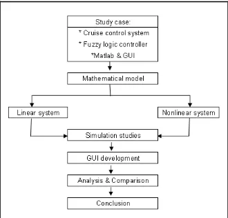
1.1 Process Flow Chart 4
2.1 Cruise control system in automobile 9
2.2 Power button on the steering. 11
2.3 A moving car modeled as a cart traveling on a float road 15 2.4 A moving car modeled as a cart traveling uphill 16 2.5 A moving car modeled as a cart traveling downhill 17 3.1 A general block diagram representing the model of
a car in motion 20
3.2 A block diagram by Lewis and Yang (1997) 21 3.3 A general block diagram representing the nonlinear
model of a car 28
3.4 Equation in DEE block for nonlinear system 30
4.1 Fuzzy controller architecture 32
4.2 Human Controlling for Cruise Control system cart 33 4.3 Fuzzy Controller for Cruise Control System Cart 33 4.4 FIS editor for linear model cruise control 36 4.5 Membership Function for input variable “error” 36 4.6 Membership Function for input variable “derror” 37 4.7 Membership Function for output variable “output1” 37 4.8 Block Diagram for Linear cruise control system
with Fuzzy Logic controller 38
xiv
4.10 Membership function for input variable “derror” 42 4.11 Membership function for output variable “output1” 43 4.12 Block diagram for linear cruise control system
with fuzzy logic controller 43
5.1 Linear system of cruise control system without
Fuzzy Logic controller 48
5.2 Step response of velocity linear system without
Fuzzy Logic controller 49
5.3 Linear system of cruise control system with
Fuzzy Logic controller 50
5.4 Step response of velocity linear system with
Fuzzy Logic controller 50
5.5 Nonlinear system of cruise control system with
Fuzzy Logic controller 52
5.6 Step response of velocity nonlinear system with
Fuzzy Logic controller 54
5.7 Output Response for linear model 55
5.8 Output Response for nonlinear model 55
5.9 Graphic User Interface for Linear Model 58
xv
LIST OF ABBREVIATION
F
nett - Nett force
Ca - Coefficient of the air-drag force C
1 - coefficient of the engine F
d - Drive Force refv - Output speed wv - Wind gust v - Speed
u - Throttle angle θ - Grading of road F
g - Gravitational force F
1
CHAPTER 1
INTRODUCTION
1.0 Introduction
Fuzzy logic was first proposed by Lotfi A. Zadeh of the University of California at Berkeley in a 1965 paper. He elaborated on his ideas in a 1973 paper that introduced the concept of "linguistic variables", which in this article equates to a variable defined as a fuzzy set. Fuzzy logic controller is most popular now in logic design controller because it easy to understand and uses rules and reasoning principle similar to the way humans think.
2
solution to non- linear control because it is closer to the real world. Non-linearity is handled by rules, membership functions, and the inference process which results in improved performance, simpler implementation, and reduced design costs
In this project, the linear and nonlinear model of intelligent cruise control system was design using fuzzy logic controller for the result to improves the high stability system and gives better performance. Other important thing, this project will demonstrate the comparison between linear and nonlinear model for artificial intelligent (fuzzy logic controller) design of cruise control system. The most common characteristic to be compared are steady state error, percentage overshoot and the settling time in order to identify a good response of the controller.
1.1 Objective
The main objective of this project is to perform and show how a fuzzy controller is tunable comparison between linear and nonlinear model for fuzzy logic controller design of a cruise control system. Secondly is to develop a linear and nonlinear system for fuzzy logic controller design of a cruise control system by using Graphic User Interface (GUI). The purpose of the GUI is to allow user to view the performance of the cruise control system clearly.
1.2 Scope
3
Works also begin with a derivation of a suitable mathematical model of a linear and nonlinear cruise control system.
Next is to analyze the response of the system using fuzzy controller and lastly, simulation will be carried out using Matlab and GUI interface and a comparative assessment of the impact of each mode l will be compared and analyzed
1.3 Proble m State ment
The problem of cruise control system is to maintain the output speed of the system as set by the input signal. For example, if a driver desires to maintain the car speed at 30 kilometer per hour, then the system should be able to produce the desired output even when the vehicle traveling downhill and uphill. Other problems encountered by the fuzzy logic controller are: (1) extracting a model from fuzzy logic system is difficult. (2) Fuzzy system requires finer tuning before they are operational. (3) Difficult to get mathematically precise linear and nonlinear models for the cruise control system using Matlab.
1.4 Project Methodology
1.4.1 Process Flow Chart
4
Figure 1.1: Process Flow Chart
Methodology approach for this project development is state as below:
1) Gathering information
5
2) System Analysis
Analysis will be done when the mathematic equation for both model of cruise control system was derived. Information from the references books and internet sources are gathered to support the validity of the analysis process. Try to understand how both linear and nonlinear of a cruise control system work in real life.
3) Simulation studies & review
Lots of time will be spent in practicing programming skills by using MATLAB 7.0 on how to implement and design a fuzzy logic controller for both cruise control system models. Note that, higher performance of proposed fuzzy controller for both model adaptive cruise control systems is expected by tuning the width and center point of membership functions and scaling factor. The tuning by evolutionary computation, such as genetic algorithms, is expected as future works.
4) Design & development
The linear and nonlinear model of a cruise control system was fully design and implemented using fuzzy logic controller in MATLAB and GUI. The purpose of the GUI is to allow user to view a performance of the cruise control system clearly.
5) Verification & comparison
6
6) Further improvement
After verification and testing complete, the program should meet the primary objectives set earlier in the duration of the project, which both linear and nonlinear model can achieve a steady state output. Any errors that occur through the system will be solved.
1.5 Thesis Outline
The first chapter of this thesis will include the background of the project, objective of this project need to achieve at the end of this project. Another, this chapter also will briefly explain the scope of the project, problem statement, methodology approach and thesis outline.
Chapter 2 will focuses on cruise control system in detail. Another, this chapter also discusses how the cruise control system works in both linear and nonlinear model related, conventional cruise control system and lastly it explains the component of cruise control system and a physical system of a cruise control system.
Chapter 3 will explain the modeling of cruise control system which starts with the derivation of mathematic modeling for cruise control system. The background study regarding mathematic modeling of a cruise control system was carried out from the general block diagram of a car in motion. Another important thing, the study also covered on the block diagram indicates precise components of the forces, the engine transfer function and the other important properties of the block diagram that was thoroughly discussed before.
7
8
CHAPTER 2
LITERATURE REVIEW
2.0 Introduction
The following discussion mainly focuses on cruise control system in detail. Another, this chapter also discusses how the cruise control system works in both linear and nonlinear model related, conventional cruise control system and lastly it explains the component of cruise control system and a physical system of a cruise control system.
2.1 Cruise Control System
What is the cruise control system? The cruise control system to regulate the vehicle speed, so that it follows the driver’s command and maintain the speed at the commanded level [3]. Other idea is, automobile's cruise control, which is a device designed to maintain a constant vehicle speed. The output variable of the system is vehicle speed. The input variable is the engine's torque output, which is regulated by the throttle [9].