ISSN: 1693-6930,
! " # $ 819
Trajectory Tracking of AR.Drone Quadrotor Using
Fuzzy Logic Controller
Agung Prayitno, Veronica Indrawati, Gabriel Utomo Electrical Engineering Department, University of Surabaya (UBAYA) Jl. Raya Kalirungkut – Surabaya 60293, East Java – Indonesia, Tel.+62-31-2981157 e-mail: [email protected], [email protected], [email protected]
Abstract
In this paper, Fuzzy Logic Controller (FLC) is implemented in the AR.Drone quadrotor in order to make it follow a given trajectory reference. The distance between the position and angle of the AR.Drone to the reference point is used as the input of the FLC. As for the output, pitch value and yaw rate will be the controlling signal for the AR.Drone. The navigation data of the AR.Drone are forward speed (vx), sideward
speed (vy), and yaw. These navigation data are going to be used to estimate positions and orientation of
the AR.Drone. To compensate for the y-position drift, the value of vy is also used as a criterion to determine
the roll compensation. The FLC algorithm is implemented to AR.Drone 2.0 Elite Edition using LabVIEW software. Also, the algorithm has been tested in various trajectories such as a straight line, a straight line with a perpendicular turn, a rectangular trajectory and a curved trajectory. The results have shown that AR.Drone can follow a given trajectory with various initial positions and orientations quite well.
Keywords: AR.Drone trajectory tracking, AR.Drone control, fuzzy logic controller
1. Introduction
A helicopter with four equally spaced rotors usually arranged diagonally is commonly known as the Quadrotor. In recent years, the quadrotor has become one of the most highly developed fields of research. This platform is chosen because of its mechanical construction which is quite simple yet able to hover in a stationary manner, to vertically descend (yaw), fly slowly, or even manoeuver swiftly. On the other hand, this aircraft has several shortcomings such as limited energy supply and limited load capacity. Another shortcoming of this aircraft is that it is quite arduous to control because the aircraft is inherently un-stable [1]. However, many applications had been produced utilizing this quadrotor, such as monitoring and analysing traffic, aerial photography and video, aerial surveillance and intelligence gathering (law enforcement), property assessment and real estate promotion etc. [2]. However, most of those applications are still operated manually by an operator on a ground station.
In order for a quadrotor to fly autonomously, naturally an autonomous flight task control, which enables the quadrotor to manoeuvre, needs to be designed. Vertical take off, landing, hover flight, tracking an object or path and trajectory tracking is included in said Autonomous flight task. The development of the design and control algorithms is quite an interesting topic to research. In order to save time, a good platform, in other words a good quadrotor in terms of its hardware, is used so that the control algorithm can be designed immediately on that platform. One of the said platforms, which is also used in this research is the AR.Drone.
According to [3], there are several layers that implements autonomous UAV. The first layer is the kernel control, which is responsible for its asymptotic stability. The second layer is the command generator, which plays a role in triggering the flight sequences command in kernel control. The third layer is flight scheduling, which is basically to set the flight plan, flight task, and references. AR.Drone has already been equipped with the first layer, which receives its flight sequences command through Wi-Fi. Angle stabilisation and vertical speed are controlled by software on-board the AR.Drone. However, the AR.Drone is yet to be equipped with the second and third layer, which allows the researcher to explore various control algorithms to implement AR.Drone, which ultimately enables the AR.Drone to perform its myriad applications.
accelerometer sensor, a gyroscope sensor, an ultrasonic sensor, microcontroller and two cameras. This platform is also equipped with a real-time operating system which enables it to perform various tasks simultaneously, such as a ground system communication through Wi-Fi, sensor acquisition, video data sampling, image processing, state estimation and closed-loop control [4].
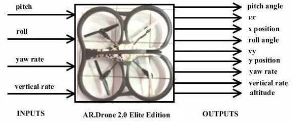
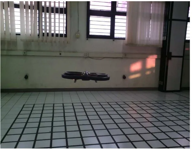
In this particular research, the type of AR.Drone used is the AR.Drone 2.0 Elite Edition, which is shown in Figure 1. Essentially this AR.Drone consists of a carbon fibre framework, aircraft chassis and a foam cover, 4 motors and propellers, inner-board electronics and 2 cameras. The essential components from the AR.Drone are as follows: 4 brushless inrunner motors. 14.5W 28,500 RPM, 1GHz 32 bit ARM Cortex A8 processor with 800MHz video DSP TMS320DMC64x, 1GB DDR2 RAM at 200MHz, 3 axis gyroscopes 2000°/second precision, 3 axis accelerometers +-50mg precision, 3 axis magnetometers 6° precision, Pressure sensor +/- 10 Pa precision, Ultrasound sensors for ground altitude measurement, 60 FPS vertical QVGA cameras for ground speed measurement, Linux 2.6.32, USB 2.0 high speed for extensions, Wi-Fi, HD Camera. 720p 30FPS [5].
The internal controller of the AR.Drone allows the user to control the flight manoeuver of the AR.Drone easily because essentially an AR.Drone is designed as a reality game. The application to control the AR.Drone is acquired easily by downloading in Google Play for Android devices or AppStore for iOS devices. Some of the said applications are AR.FreeFlight 2.0 and AR.Race 2. However, Parrot, as the producer of the AR.Drone had also included a Software Development Kit (SDK) [6] which enables the users to access the AR.Drone through Wi-Fi to control it, design their own control algorithm, and perform various data acquisition through various software.
Through the included internal controller, the users are able to do a few basic controls, which already covered take-off, landing, hover and emergency stop. Each and every one of those control commands has closed-loop control in the internal controller of the AR.Drone. As an example of take-off command, the internal controller will do several things in sequence as follows: [7]
• Start the motors.
• Increase the amount of thrust on all of the propellers uniformly in order to raise the altitude of the AR.Drone until it reaches its stable point (approximately 1 metre).
• Make sure that the speed of the rotor is still at zero attitudes (roll, pitch) and zero yaw. • Monitor the bottom camera in order to retain the drone’s position just above its take-off point.
In addition to those basic control commands, the users are also able to control the manoeuever of the AR.Drone, such as pitch, roll, yaw rate and vertical rate. When all these four inputs are null (zero in value) then, automatically, the drone will function, as it will be in a hover condition. The outputs of the AR.Drone can actually be recorded, which are as follows: actual roll angle, forward speed vx, x-position estimation, actual roll angle, sideward speed vy, y -position estimation, yaw rate, yaw estimation, vertical rate, altitude, video from bottom camera and front camera.
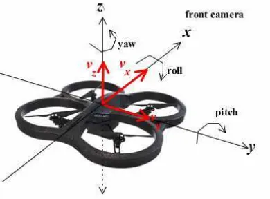
AR.Drone has six degrees of freedom (DOF), which are three translational components (position at x, y, z axis) and three rotational components (pitch, roll and yaw angles) as shown in Figure 2. The central point of the AR.Drone is actually the centre of the coordinates with the x
axis in the same direction as the front camera. The translational speed of the AR.Drone is stated with forward speed vx, sideward speed vy and vertical speed vz. Pitch is an angle of the rotational movement of the AR.Drone on the y-axis, while roll is the angle of the rotational movement of the AR.Drone on the x-axis, and yaw is the angle of the rotational movement of the AR.Drone on the z-axis. Those variables are the output of the AR.Drone, which is caused by the combination of the four control signal inputs (roll rate, pitch rate, yaw rate, and the vertical rate).
Figure 2. AR.Drone’s degree of freedom
Prior to this research, many researches have been made with various types of quadrotor and with AR.Drone as their platform. Michael Mogenson [8] created the AR.Drone LabVIEW toolkit which enables researchers, lecturers or students to further their understanding of the AR.Drone 1.0. With this toolkit it is possible for the users to control, read navigation data and analyse picture data from both of the on-board cameras. Krajnik et al. [1] explained how the AR.Drone is suitable as the platform for various research and educational purposes. In that paper, the hardware and the software of the AR.Drone, how to acquire various data such as model dynamic from its drone system using data modelling, and some basic algorithms to obtain position stabilization, object following and autonomous navigation are described and explained. Sun Yue [9] modelled and identified several model parameters through various experiments. According to the dynamic model obtained, the local controller, global controller and filter are designed. To control throttle, roll, pitch, and yaw a local controller is used. While for the position control, a global controller is used with Kinect as the sensor. The filter is used in order to reduce the amount of noise at the sensor. Jacco and Mario [3] used a combination of GPS sensor and barometer sensors in order to determine the position of the drone. The GPS sensor is used to determine the horizontal position while the barometer is used for the altitude of the drone. Guilherme et al. [10] used a predictive and nonlinear robust control to solve path-tracking problems on quadrotors. They used MPC for solving the trajectory path-tracking and non-linear H∞ controller for stabilization of the rotation.
In this paper, the fuzzy logic controller is designed and implemented in AR.Drone 2.0 Elite Edition in order to follow a given reference trajectory in space coordinate. The controller itself will be implemented using LabVIEW software. An example of the application of this algorithm is autonomous flight control with various manoeuvres for entertainment purposes.
2. Research Method
purpose, AR.Drone LabVIEW Toolkit [8],[11], which is designed for AR.Drone 1.0 was re-modified so that its block diagram and front panel is suitable for the AR.Drone 2.0. A few of the most important modifications which were carried out were updating the firmware to the 2.4.8 version, modifying the delivery of AT*REF and AT*PCMD to make it send alternately, improving the computer access communication with user datagram protocol (UDP) on its on-board electronics, and also adjusting the front panel so that it satisfied the control, data acquisition and monitoring requirements when implementing the trajectory tracking in this research. To summarize, the result of the final modification means the computer program will have a data flow as shown in Figure 3.
Figure 3. Data flow program at LabVIEW for AR.Drone 2.0
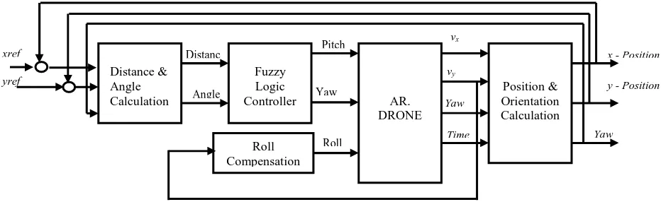
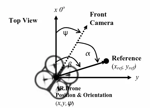
The next stage is to design the control scheme, which will be applied in the AR.Drone. The controlled system block diagram, which will be used in this research, is shown in Figure 4. Essentially, there are five subsystems as follows: subsystem AR.Drone, subsystem fuzzy logic controller, subsystem distance and angle calculation, subsystem position and orientation calculation, and also subsystem roll compensation. The subsystem of the AR.Drone is a system within the AR.Drone, which is controlled via Wi-Fi and prepared at previous stages. Subsystem distance and angle calculation prepared the value of distance and angle which are the inputs of the fuzzy logic controller. The value of distance (r) is the distance between reference points (xref,yref) and its current position (x,y), while the angle () is the angle between the reference point () and its current orientation (ψ) as shown in Figure 5.
Figure 5. Distance and angle calculation
The distance (r) can be obtained using equation (1).
2
2 ( )
)
(x x y y
r= ref − + ref − (1)
While the angle () calculation is made with an algorithm as follows:
180
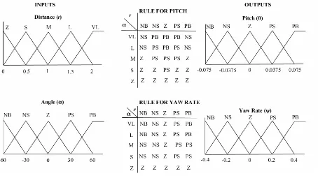
The fuzzy logic controller’s subsystem has two inputs, which are distance (r) and angle () and two outputs which are pitch (θ) and yaw rate (ψrate). For the distance input, in this research, the range of distance used is from 0 to 2 metres and is stated in five triangular membership functions. For the angle input, the range of angles used is from -60o to 60o, which is also stated in five triangular membership functions. The output pitch varies from -0.075 to 0.075, which is divided into five triangular membership functions. While yaw rate varies from -0.4 to -0.4 and is also divided into five triangular membership functions. With two kinds of inputs with each of the five membership functions and also two outputs, then a 2x25 rule is used in this
particular fuzzy logic controller. The defuzzification output used the centre of gravity method. Further details of this design are shown in Figure 6.
Figure 6. Fuzzy Logic Controller
Subsystem position and orientation calculation is used in order to determine the position and orientation of the AR.Drone using forward speed (vx), sideward speed (vy), yaw (ψ) and time stamp (t) data. Those calculations can be solved using the algorithms below.
if RESET = TRUE then
Yawreset = Yawi;
x = 0; y = 0;
else
Yawreset = Yawreset; dx=(Timei – Timei-1) ⋅⋅⋅⋅ Vx;
dy=(Timei – Timei-1) ⋅⋅⋅⋅ Vx; end if
Yawvalue = Yawi – Yawreset;
xi = xi-1+dx⋅⋅⋅⋅ cos(Yawvalue)+dy⋅⋅⋅⋅ cos(Yawvalue+90);
yi = yi-1+dx⋅⋅⋅⋅sin(Yawvalue)+dy⋅⋅⋅⋅ sin(Yawvalue+90);
Where, i is the number of sample. When RESET is done, the position and orientation of the AR.Drone is set to (0, 0, 0). In order to reset the orientation of the AR.Drone, Yawreset
variable, which will reduce the amount of yaw at that time (Yawi) so that its value (Yawvalue) becomes 0 is used.
Roll compensation is a subsystem that compensates for the sideward speed (vy) during trajectory tracking. This compensation is achieved simply by giving the AR.Drone an input value called roll, which varies from 0.3 to -0.3 for a sideward speed of -0.6 to 0.6 m/s proportionally.
are carried out in the Industrial Automation Laboratory Building TC.3 Electrical Engineering University of Surabaya with room dimensions of approximately 4x4 metres. The testing procedure is as follows:
• Generate reference trajectory in its various shapes.
• The data trajectory, which has been generated, is called through a program as the setpoint that is to be followed by the AR.Drone.
• AR.Drone is flown from its initial position and orientation using hover mode.
• After the altitude is stable at 1 metre, switch to auto by turning hover mode off. AR.Drone will follow a given trajectory using the fuzzy logic controller.
• AR.Drone will be set back to hover mode at the end of the trajectory. In order to ease the monitoring, a reference trajectory graph and real time experiment is made at the front panel of LabVIEW.
• After the experiment is complete, AR.Drone is landed.
Figure 7 and 8 show the real time experiment and the front panel of LabVIEW.
Figure 8. Front Panel
3. Results and Analysis
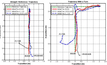
The results of the fuzzy logic controller for a several reference trajectories are shown in this section. The first testing is conducted in a straight reference trajectory. The AR.Drone is tested with various initial positions before being flown autonomously with the designed controller. Furthermore, the AR.Drone is tested using a trajectory that has a perpendicular turn to the right. As before with the straight trajectory, the drone is tested from various initial positions to see the capabilities of the drone in following a given trajectory. Figure 9 shows the result on a straight reference trajectory and on a trajectory with a turn.
-2.5 -2 -1.5 -1 -0.5 0 0.5 1 1.5
According to the results above, the AR.Drone is capable of following the straight trajectory well. At the initial position (1,-1, 0), the angle between the AR.Drone and the reference trajectory is very large so that when the AR.Drone is heading towards its trajectory, a relatively small overshoots occurred. When the AR.Drone is given the same initial position and orientation as the initial reference, naturally the AR.Drone completed its task. Likewise, when the initial position and orientation of the AR.Drone has a relatively small angle compared to the reference trajectory (in this case (-0.2, 0.4, 0), it is easy for the AR.Drone to follow the trajectory.
It is shown that generally the AR.Drone has shortcomings in following a given trajectory with a turn. The position of the AR.Drone appeared to be lagging when compared to its reference. Nevertheless, from various initial positions, the AR.Drone has shown its capability in following a given trajectory.
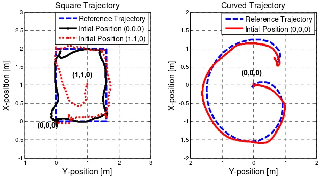
In the next experiment the trajectory is changed into a square. Naturally, various initial positions are used in order to see the drone’s response. The last experiment is a curved trajectory with the shape of a letter ‘G’. The reference of this trajectory is obtained by recording the navigation data of the AR.Drone which was manually flown with a program from a ground station which gives the pair of pitch and yaw rate sequentially. Figure 10 below shows the result of the experiment of the said curved trajectory. The results are shown in Figure 10.
-1 0 1 2 3
Figure 10. The results of AR Drone with a square’s trajectory and a curved’s trajectory
It is shown once again that the same shortcomings occurred in each turn. However, when the trajectory is straight, the AR.Drone is able to follow it well. The AR.Drone is also capable of following the trajectory even though its initial position is in the centre of the square trajectory. Generally the AR.Drone is able to follow a curved trajectory well even though there are still some errors in the position of x and y which are relatively small.
4. Conclusion
In general, The Fuzzy Logic Controller can be used to solve the trajectory-tracking problem in AR.Drone. From the experiments that have been carried out, the drone is shown to be capable of following a given trajectory with various initial positions. However, there are still some shortcomings in this research, which include the lagging of the drone when following a turn in a trajectory, especially the sharp ones.
References
[1] Krajnik T, Vonasek V, Fiser D, Faigl J. AR-Drone as a Platform for Robotic Research and Education. Research and Eductation in Robotics :EUROBOT. Heidelberg. 2011.
[3] Jacco vand der Spek, Mario V. AR.Drone Autonomous Control and Position Determination. Bachelor Thesis. TU-Delft. 2012.
[4] Pierre-Jean B, Francois C, David V, Nicolas P. The Navigation and Control Technology Inside the AR Drone Micro UAV. 18th IFAC World Congress, Milano Italy. 2011.
[5] http://ardrone2.parrot.com accessed on 11 August 2014.
[6] Stephane P, Nicolas B. AR.Drone Developer Guide. Parrot. SDK 1.6. 2011.
[7] Gerrard M. Modeling and Control of the Parrot AR.Drone. SEIT UNSW Canberra. Final Project Report. 2012.
[8] Michael M. The AR Drone LabVIEW Toolkit: A Software Framework for the Control of Low Cost Quadrotor Aerial Robots. Master of Science Thesis. TUFTS University. 2012.
[9] Sun Y. Modeling, Identification and Control of a Quadrotor Drone Using Low-Resolution Sensing.
Master of Science Thesis. University of Illinois at Urbana-Champaign. 2012.
[10] Guilherme V R, Manuel G O, Francisco R R. Nonlinear H