DOI: 10.12928/TELKOMNIKA.v14i3A.3117 1
Study on Reactive Power and Harmonic Characteristics
of DC Ice-melting Technology based on RTDS
Simulation and Field Test
Lin Xu1, Yang Han*2 1
State Grid Sichuan Electric Power Research Institute, No. 24, Qinghua Road, Chengdu, China 2
Department of Power Electronics, School of Mechatronics Engineering, University of Electronic Science and Technology of China, Chengdu, China
*Corresponding author, e-mail: [email protected]
Abstract
To study the characteristics of reactive power and harmonic of 500kV DC de-icer, the ice-melting technologies including the calculation method of critical ice-melting current, ice-melting time and maximum ice-melting current are clarified. The detail ice-melting methods and strategies for the 500kV transmission lines are proposed. Based on the ice-melting current calculation of Kang-Ding substation transmission lines in Sichuan, China, the 500kV/150MVA DC de-icer is deployed for the 500kV transmission lines. The effectiveness and feasibility of the ice-melting algorithm is validated by the RTDS simulation and the field test results. It is proved that the harmonic distortions of voltage and current are increased with the increasing ice melting current, which can be improved by the installation of passive filters.
Keywords: DC de-icer, Real time digital simulator (RTDS), ice-melting current, deicing operation mode, harmonic and reactive power characteristics
Copyright © 2016 Universitas Ahmad Dahlan. All rights reserved.
1. Introduction
Icing disaster of AC and DC transmission lines in winter is one of the major natural disasters in power system, which would cause the power supply interruption, even power system splitting accident. The repair work is difficult and of long period. Therefore, the DC de-icer is necessary for ice melting of AC and DC transmission lines [1-4].
From the existing literature, the dc-current ice-melting and over-current ice-melting methods are two feasible means of de-ice melting schemes [5, 6]. By using the dc-current ice-melting method, the required power capacity of power electronic converters can be greatly reduced since the efficiency is not affected by the line reactance. The icing lines are perceived as the load with dc power supply, which provides a short-circuit current with a lower voltage rating. Two schemes can be adopted for heating of the icing wires, one adopts the power rectifier at the generator side and another scheme adopts the converter at the network side. Although the first approach reduces the investment, due to the limited capacity of the generator and the large amount of power consumed by the icing lines, it is impractical for most of the cases. Therefore, the dc ice-melting method based on the thyristor converter is the preferred solution with a higher level of robustness, and the dc-voltage can be adjusted dynamically under different circumstances [7-9].
melting process. Therefore, the ice-melting currents of the dc transmission lines must be determined first.
The heat generated by the ice-melting currents in the conductors is to increase the conductor temperature to the melting point hence the icicles melt. A portion of the power loss dissipates when the heat is transferred to the surface of conductors and another part of loss dissipates across the surface, with the following analytical expression:
2
where Ir denotes the ice-melting current (A), R0 denotes the resistance of conductor at 0°C (Ω/m), Trdenotes the ice-melting period (h), ∆t denotes the temperature difference between the conductor and air (°C), g0 denotes the density of ice (g0=0.9 in case of glaze ice), b denotes ice thickness, D denotes outer diameter of conductor with glaciation (cm), RT0 denotes the equivalent thermal-conduction resistance of the ice layer (°C.cm/W), which is described as:
0 273
where d denotes conductor diameter (cm), λ denotes thermal conductivity (W/°C.cm), λ=0.0227 in case of glaze, and λ=0.0012 in case of soft rime.
The parameter RT denotes the equivalent thermal resistance for convection and radiation (°C.cm/W), in case of glaze, RT can be written as:
2 3
2.2. Selection of Ice Melting Mode
Under normal circumstances, the three-phase transmission lines at the AC-side are shorted, by controlling the firing angle of the converter, the dc-side currents would result in ice-melting effects for the ice across the three-phase transmission lines at the AC-side.
The two ice-melting circuit configurations are shown in Figure 1 and Figure 2, respectively. Figure 1 shows the circuit diagram of the “I-I type” ice-melting system, where the ice-melting period is T for the individual transmission line. Hence, the total time period for the three transmission lines is 1.5T. Figure 1(a) shows the case of A-C mode, where the circuit breakers WPQ11 and WNQ11 are closed for a period of 0.5T. Figure 1(b) and Figure 1(c) show the case of B-C and A-B mode respectively.
The alternative approach using “I-II type” configuration is shown in Figure 2. Under this scenario, the total time for ice-melting process is 2T. Figure 2(a) shows the case of AB-C mode, where the circuit breakers WPQ11, WPQ12 and WNQ11 are closed for a period of 2T/3, and the transmission lines for phase A and B are connected in parallel, and then connected in series with phase C. Figure 2(b) shows the case of AC-A mode.
(a) (b) (c)
Figure 1. The “I-I type” ice-melting configurations: (a). A-C mode; (b). B-C mode; (c). A-B mode
(a) (b)
Figure 2. The “I-II type” ice-melting configurations: (a). AB-C mode; (b). BC-A mode
2.3. Ice-Melting Scheme
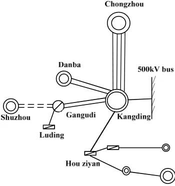
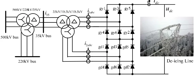
The presented ice-melting device was installed at Kangding station, which is the hub for the sending channel of the 500kV transmission lines for the Sichuan hydropower. Figure 3 shows the connection between Kangding station and its surrounding system, such as Chongzhou, Danba, Gangudi, Hou ziyan station. These 500kV lines is connected at the two poles on the DC-side of the ice-melting device by the I-I type or I-II type, shown as Figure 4, where the ∆-∆-Y rectifier transformer is connected at the 35kV bus side, two 6-pluse rectifiers are connected at the 10kV bus side of the transformer, separately.
2abc
i
Figure 4. The schematic diagram of ice-melting device for transmission system
According to the Equation (1) and the parameter of the ice-melting line, the ice-melting current idc, DC voltage Udc, active power P, reactive power Q and the firing angle θ are calculated preliminarily shown in Table 1. It can be found that the ice-melting current and dc voltage are different for the different types and lengths of 500kV lines. Once the input line voltage of the rectifier is certain, the lower the DC output voltage is, the greater the firing angle and required reactive power are.
Table 1. The calculation result of different 500kV lines
500kV line name R(Ω/km) L(km) idc(A) θ(°) P(MW) Q(MVar) Udc(kV)
Kangding-gangudi 0.01158 32.5 5000 77.44 20.07 130.53 3.71 Kangding-chongzhou 0.01158 202.5 5000 19.67 117.32 63.55 23.45 Kangding-Chongzhou 0.01158 200 5000 21.16 115.82 66.07 23.16
Kangding-danba 0.01478 109 4500 52.01 65.02 99.41 14.56 Kangding-Hou ziyan 0.01808 50 4000 70.76 29.01 102.08 7.23
3. Implementation of Ice-Melting Controller on RTDS Platform
Figure 5 shows the physical interface system (including power amplifier) of ice-melting controller with the RTDS simulation system. The RTDS simulation device provides the desired voltage Udc, current idc and the 35kV bus voltage, and also provides the ice-melting controller with the switching positions of the filter branches, the dc-side breaker. As shown in Figure 5, the rectifier trigger signals as well as the opening/closing of each branch switching signals generated by the ice-melting controller are sent back to the RTDS platform. Furthermore, the controller acquires the voltage, current and switching position signals from the physical interface box (including the power amplifier). After the execution of the complicated control algorithm, and output trigger pulse signals and sub-closing signals of the ice-melting controller are sent back to the RTDS platform. Following the last procedure, the closed-loop controller test of the ice-melting device is realized in the advanced digital power system simulation RTDS platform.
500kV/220 kV/35kV voltage and the 11th, 13th harmonic components under different ice-melting current conditions.
Figure 5. The closed-loop test system of the De-icer controller and the RTDS platform
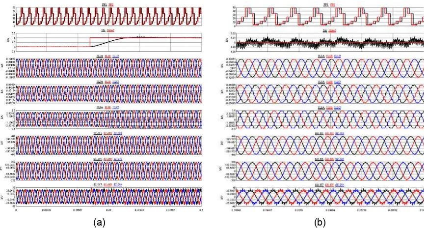
As shown in Figure 6, the De-icer can keep at the reference ice-melting current, when the reference is changed, the dc-side current has a small fluctuation and reaches to the given value soon, the steady error is nearly zero. According to the limit of IEEE 519-1992 standard for the harmonic injection to the utility grid, the THD for 35kV voltage should be less than 3.0%, and the THD for 220 kV and 500kV voltage should be less than 2.0%. Due to the short circuit capacity of the station is 2062MVA, and then the limitations of 11th and 13th harmonic current imposed by the IEEE standard are 46.2A and 38.8A, respectively.
(a) (b)
Q(MVar) 16.01 29.5 55.95 81.67 106.76 130.53 500kV voltage THD (%) 0.095 0.22 0.44 0.63 0.79 0.9
220kV voltage THD (%) 0.24 0.55 1.11 1.59 2 2.28 35kV voltage THD (%) 0.89 2.1 4.24 6.17 7.77 8.95 35kV 11th current(A) 25.67 46.85 87.9 127.67 162.92 195.66
35kV 13th current (A) 13.34 31.13 66.02 98.16 128.68 153.59
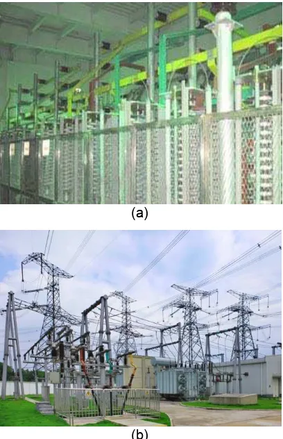
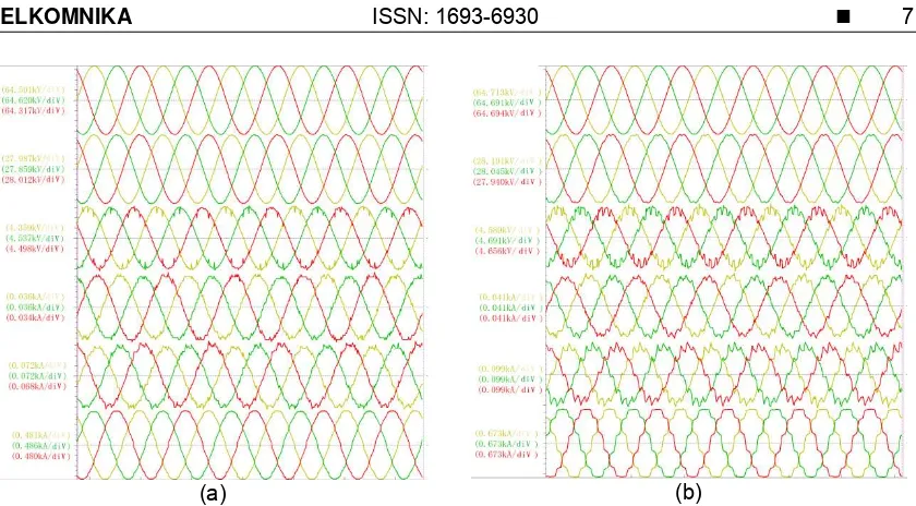
4. Field Result
The proposed 150MVA DC de-icer was implemented in the 500kV Kangding station, as shown in Figure 7. Due to the similarity of the field results, Figure 8 shows the test results when the ice-melting current are 1000A and 5000A using I-I type ice-melting mode, respectively. We can see that the distortion of voltage and current in each side of the transformer increased significantly when the ice-melting current changes from 1000A to 5000A. Meanwhile, Figure 9 shows the test trend of 11th and 13th harmonic component and ratio with the varying ice-melting current. During the time [0, 130min], the ice-ice-melting current increased from 0A to 5000A with the step increase of 1000A, the 11th harmonic voltage distortion rate increases from 0.2% to 5.7%, the 11th harmonic current component increases from 0A to 190A, the 13th harmonic voltage distortion rate increases from 0.2% to 6.3%, the 13th harmonic current component increases from 0A to 148A. And then, during the time [130min, 170min], the current reduced from 5000A to 0A. It can be found that the field result is consistent with the RTDS simulation result, which verifies the validity of the proposed DC de-icer techniques.
(a)
(b)
(a) (b)
Figure 8. The voltage and current waveforms at each side of the 500kV transformer. (a) I-I type ice-melting mode, idc=1000A), (b) (I-I type ice-melting mode, idc=5000A)
(a) (b)
Figure 9. The test trends of harmonic current and voltage with the varying ice-melting current. (a) the 11th and 13th harmonic current of the 35kV line, (b) the 11th and 13th voltage distortion
rate of the 35kV line.
5. Conclusion
According to the actual application of dc de-icing technology at 500kV Kangding station, it can be concluded that timely applied de-icing play an essential role in protecting transmission lines and towers from damage, lowering line trips, and ensuring system safety.
To study the characteristics of reactive power and harmonic of DC de-icer, the deployment principle of dc de-icers in a grid and an optimized de-icing dispatch strategy taking into account more constraints has been initiated. The RTDS simulation model of 500kV Kangding station with 180MVA DC de-icer model and dc de-icing technology is introduced in detail. With this model, the characteristics of reactive power and harmonic at the Kangding station are analyzed. Also the application of DC de-icer in Kangding station is also given, which shows that DC de-icer is an effective means to tackle the ice disaster for transmission lines.
References
[5] Huneault M, Langheit C, S-Arnaud R, et.al. A dynamic programming methodology to develop ice-melting strategies during ice storms by channeling load currents in transmission networks. IEEE Transaction on Power Delivery. 2005; 20(2): 1604-1610.
[6] Horwill C, Davidson C C, Granger M. An application of HVDC to the ice-melting of transmission lines. Proceedings of the 2005/2006 IEEE PES Transmission and Distribution Conference and Exhibition, Dallas, TX, USA. 2006: 529-534.
[7] Xie Huifan. Modeling of Gao-Zhao HVDC with deicing function based on EMTDC. Proceedings of the Asia-Pacific Power and Energy Engineering Conference, Wuhan, China. 2011: 1-4.
[8] Xie Huifan, Wang Haijun, Chen Qian. Analysis on reactive power and harmonics of Gao-Zhao HVDC under deicing operation mode. Automation of Electric power systems. 2011; 35(19): 77-84.