DOI: 10.12928/TELKOMNIKA.v13i3.1972 806
A Real-time SAR Echo Simulator Based on FPGA and
Parallel Computing
Xu Yinhui*, Zeng Dazhi, Yan Tao, Xu Xiaoheng
Department of Electronic Engineering, School of Information and Electronics, Beijing Institute of Technology, Beijing 10008, China
*Corresponding author, e-mail: [email protected]
Abstract
This paper designs and implements a SAR (Synthetic Aperture Radar) real-time echo simulator based on multi-FPGA parallel computing. The one-dimensional frequency-domain Fourier transform algorithm is used in the simulator, and the echo signal model and the rapid calculation algorithm of impulse response function are introduced. The pipeline compute structure, multichannel parallel computing and procedure flow design are the key technologies of the simulator, which are also presented in details. And finally, the validity and correctness of the SAR echo simulator are verified through the imaging results of the point-array target and the nature scene target.
Keywords: SAR, real-time simulator, DRFM, parallel computing
Copyright © 2015 Universitas Ahmad Dahlan. All rights reserved.
1. Introduction
SAR real-time echo simulator is equipment for SAR test and evaluation, and it has aroused more and more concern from scholars and engineers nowadays [1-3]. SAR real-time echo simulator receives transmitted signals during pulse repetition time (PRT), and it acquires the echo signal through convolution of the transmitted signal and the target scene information [4]. Because of the wide coverage offered by the antenna beam, the large image resolution required, and the long PRT, the demands on computing power are strict and real-time capabilities are limited [5, 6]. Wen Liang from the Beijing Institute of Technology proposed a multi-chip DSP parallel computing SAR real-time simulator but the delay of the simulator is too long [7]. Yi Yongjun et al and Sachin B. et al proposed a FPGA-based SAR simulator, but it must perform two separate FPGA calculations, which limits its computing capacity and cannot be used to perform real-time simulations [8, 9].
This paper describes the design and implementation of a SAR real-time echo simulator based on multi-FPGA parallel computing architecture and DRFM (Digital RF Memory) technology. This method can realize real-time SAR echo depiction of natural scene targets. First, the signal model of SAR echo and one-dimensional frequency-domain Fourier transform algorithm are introduced. Then, the system design and key technologies of the real-time SAR echo simulator are presented in Section 3 and Section 4. Finally, the simulator’s performance is tested by the imaging results of points-array target and nature scene target in Section 5.
2. Signal Model
SAR generally uses LFM signal as the transmitting signal, which can be written as follows:
2
exp r
p t a t j k t ,
1,00,otherwise
t
a t
(1)
Here, kr is the slope of LFM signal, and
is the pulse width.The echo of multiple targets can
phase, which does not change with the fast time t.
In the stop-go-stop hypothesis, the SAR target scene is considered as a linear system, so the SAR echo can be determined using the convolution of the target scene’s impulse response function and the transmitted signal.
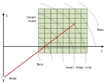
The distance between radar and target is continuously distributed, so the impulse response of the scene target h(t,n) is not a discrete function which is not suitable for FPGA to compute. The equal range ring’s division can indicate the impulse response sequence of the scene target R.
equal range ring
Figure 1. Sketch map of equal range ring
The minimum distance from the radar platform to the target scene is Rmin, the maximum
distance from the radar to the target point is Rmax, and the interval of equal range ring is ∆sp. So
the index of the point target can be calculated as follows.
m in
To eliminate the Doppler phase error brought on by the discrete R, the phase of the equivalent backscattering coefficient needs to be corrected as shown below.
4r
Using the formula given above, the impulse response of the scene h(t,n) can be determined, by a convolution with the acquired transmitted signal p(n), the radar echo signal is obtained. The calculation process is generally divided into two parts: the impulse response calculation and the convolution calculation.
3. System Description
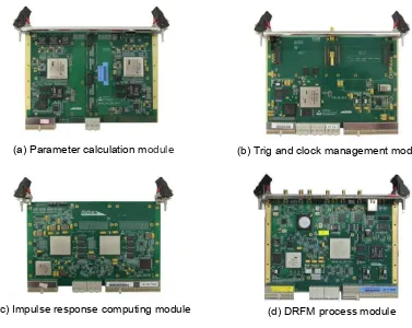
The SAR real-time echo simulator in this paper includes four modules: the parameter calculation module, trig and clock management module, impulse response function computing module, and DRFM process module. All four modules are T2FP6U boards and integrated into a 7U Compact PCI enclosure. The function of each module is explained below:
(1) Parameter calculation module: generation of SAR flight path and target-scene before testing and real-time calculation of simulation parameters.
(2) Trig and clock management module: receipt of the sync PRT trig and clock from SAR to synchronize the radar and the simulator.
(3) Impulse response function computing module: receipt of the SAR imaging parameter from parameter calculation module and real-time calculation of the impulse response function by multi-FPGA parallel computing [10].
(4) DRFM process module: receipt of the transmitted signal from radar, receipt of the impulse response function from the impulse response function computing module, and the convolution of the two signals in frequency domain.
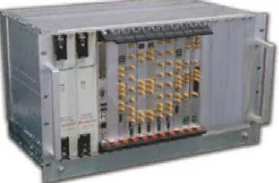
The PCB boards of the four modules are shown in Figure 2 and the enclosure of the real-time SAR echo simulator is shown in Figure 3.
(a) Parameter calculation module (b) Trig and clock management module
(c) Impulse response computing module (d) DRFM process module
Figure 2. PCB Boards of the real-time SAR echo simulator
Figure 3. Enclosure of the real-time SAR echo simulator
4. Key Technologies
4.1. Pipeline Structure of Single Impulse Response Computing Channel
Impulse response computing is performed in the core module of the SAR simulator and constitutes 90 percent of the simulator’s total computation. So it is the greatest challenge to the real-time echo simulation. This paper presents a multichannel parallel computing method with pipelined structure to solve the problem.
According to FPGA’s computing architecture and resources [11], the calculation channel has a pipelined structure, as shown below. This structure can complete one target point with one cycle. The system clock is set to 100 MHz and the system delay is set to 60 cycles, so the throughput is 100M point/s and the latency is 600ns.
arg(x , y ,z ) target amplitude
Complex
index floor R R sp
Figure 4. Pipeline of single-impulse response computing channel
The steps of the calculation process are explained below:
Step 1: After R2 is calculated using the radar’s position (xs, ys, zs) and the target’s position (xt, yt, zt), R
R
can be approximate obtained by a four-order Taylor series expansion.Step 2: Using R multiplied with the input parameter
1
sp
, theindex
index parameter is obtained, and it can be used to prevent division operations in FPGA.Step 3: By the operation of ∆R,
and the target phase θ, the corrected Dopplerequivalent phase θ′ can be determined.
Step 4: Equivalent phase was calculated by using reference look-up tables to get the real part and the imaginary part of final reflections coefficient.
Step 5: The calculated and real and imaginary parts of the reflection coefficient of the equivalent, was added to the impulse response stored in the RAM.
4.2. Multichannel Parallel Computing and Mass Data Gathering
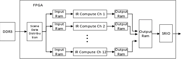
The parallel computing of impulse response is divided into two-stage computing: multichannel parallel computing in single FPGA and multi-FPGA parallel computing. An impulse response computing module includes four FPGAs (Xilinx Virtex6 sx315t), and 12 impulse response computing channels can be integrated into one sx315t FPGA. Each channel has one input ram and one output ram. The target scene which need to be processed is divided into 12 small pieces and each input ram of the impulse response stores the piece of the scene to be computed in the next PRT. The output-RAM stores the impulse response sequence of the channel. The impulse response sequences of 12 channels are added together to produce the impulse response sequence of the whole target scene.
Input
Ram
Output
Ram IR Compute Ch 1 Input
Ram
Output Ram IR Compute Ch 2
Input Ram
Output Ram IR Compute Ch 12
Scene Data Distribu
ti on
DDR3 Output
Ram SRIO FPGA
Figure 5. Multichannel parallel computing in single FPGA
The throughput of 12 channels per FPGA is 1.2G/s, so the total processing capacity of the simulator is 9.6G/s. In order to produce multi-chip interconnections between the 8 FPGAs, the simulator uses RapidIO protocol for data transmission. All impulse responses obtained through impulse response computing FPGA are sent to the DRFM process FPGA, to produce the final impulse response scene.
4.3. Procedure and Assessment of Timeliness
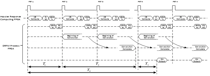
The real-time SAR echo simulator is a HIL (hardware-in-loop) test equipment. It must synchronize the clock and PRT with the radar under test. After receiving the transmitted radar signal, the HIL equipment has to generate the echo signal with the correct frequency at the right time. In the go-stop-go assumption, this time scale of simulation is PRT. This indicates that the impulse response computing and convolution computing complete every PRT.
The procedure flow of the simulator is as shown in Figure. 6. The simulator needs to complete impulse response calculation of 4M (2048x2048) target points, the throughput of the entire simulator’s impulse computing can reach 9.6G/s, and the processing time is about 410μs. The first-level parallel computing convergence is performed in FPGA, and the transfer time is approximately 10μs. The second-level parallel computing multi-chip FPGA converges through RapidIO, and the transmission delay is large, about 100μs. For these reasons, the time of single-impulse response calculation is about 520μs. Generally the PRF of SAR is under 20kHz, so the simulator can meet the demand of real-time generation.
FPGAs generally calculate the convolution on the frequency domain by FFT. The first advantage of such convolution is computationally efficient, and the second advantage is suitable for FPGA implementation. However, the normal FFT process requires at least 10μs, which is longer than normal PRT. So this paper chooses the pipelined streaming I/O mode FFT core used here has a throughput of the required input sequence cycle. In this way, it is possible to meet the needs of PRT.
IR
Com pute
Impulse Response
Computing FPGA DCFI SRIO Figure 6. The procedure of the simulator
5. Process Example
In this section, the precision of the simulator is measured by the image results of the 9-point-array target, and the effectiveness and real feature of the simulator are tested by the image results of the nature scene target. The SAR system parameters are listed in Table 1.
Table 1. SAR system parameters
Parameter Value Parameter Value Wavelength(m) 0.03 Resolution(m) 10 Pulse width(us) 5 PRF(Hz) 1336
Signal bandwidth(MHz) 60 Radar Height (km) 750 Sample frequency(MHz) 100 Radar Velocity(m/s) 7500
5.1. Imaging Results of Points-Array Target
The echo data of the 9-point-array target generated by the simulator is acquired and stored. Then, imaging is processed by CS algorithm using the complex floating point echo data. Evaluation result is shown below:
(a) image of 9-point-array target
Azimuth
Range
Two‐dimensional contour lines
(b) performance evaluation map
Figure 7. Image result of 9-point target array
Table 2. Evaluation result of SAR image quality
Parameter Range Azimuth PSLR(dB) 17.91 12.41 ISLR(dB) 12.78 7.02 Main lobe width (m) 8.42 6.52
5.2. Image Results of Nature Scene Target
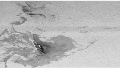
Similar to points-array target’s simulation, the echo data of 2400x1320 pixels nature scene is generated by our simulator, and the image result is shown in Figure 8, which proves that the reliability and real feature of the simulator can meet the demand of the real-time simulation.
Figure 8. Imaging result of nature scene target
6. Conclusion
This paper designs and implement a SAR real-time echo simulator based on FPGA parallel computing and DRFM technology. The signal model, hardware system and key technology are mentioned above. Finally the accuracy and real-time feature are verified and validated by the imaging results of the points-array target and nature scene target, which proves that the SAR real-time echo simulator in this paper has great practical significance and engineering value to the development and test of SAR.
References
[1] S Cimmino, G Franceschetti, A Lodice. Efficient Spotlight SAR Raw Signal Simulation of Extended Scenes. IEEE Transactions on Geoscience and Remote Sensing. 2003; 41: 2329-2337.
[2] F Wang, Hai-xia Yue, Ru-liang Yang. Distributed Target’s Raw Data Simulation of Spaceborne SAR.
Journal of Electronics & Information Technology. 2004; 26(8): 1250-1255.
[3] Quan Sun, Jianxun Zhang. Parallel Research and Implementation of SAR Image Registration Based on Optimized SIFT. TELKOMNIKA Indonesian Journal of Electrical Engineering. 2014; 12(2): 1125-1131.
[4] Zhang Shunsheng. Synthetic Aperture Radar natural scenes echo Simulation Technology. Beijing Institute of Technology doctoral thesis. 2007: 32-37.
[5] Q Peng, W Zhang, Z Zong. Design and implementation of fast SAR echo simulation based on FPGA. 9th European Conference on Synthetic Aperture Radar (EUSAR). 2012: 344-347.
[6] Franceshetti G, Riccio D, Schirinzi G. A SAR raw signal simulator. IEEE Transactions on Geoscience and Remote Sensing. 1992; 01: 110-123.
[7] Liang Wen, Zeng Tao. Design and Implementation of Real-time SAR Echo Simulator for Natural Scene. 8th European Conference on Synthetic Aperture Radar (EUSAR 2010). 2010: 1-4.
[8] Yi Yongjun, Zong Zhulin, Tian Zong. A Real-time SAR Echo Simulator for Natural Scene Based on FPGA. Modern Radar (China). 2013; 35(2): 13-17.
[9] Sachin B Jadhav. A Novel High Speed FPGA Architecture for FIR Filter Design. International Journal of Reconfigurable and Embedded Systems (IJRES). 2012; 1(1): 1-10.
[10] Marufuzzaman Mohammad, Reaz Mamun Bin Ibne, Rahman Labonnah Farzana, Chang Tae Gyu. A high speed current dq PI controller for PMSM drive. Tehnicki Vjesnik. 2014; 21(3): 467-470.