VOL. 11, NO. 14, JULY 2016 I SSN 1819- 6608
ARPN Jour nal of Engineer ing and Applied Sciences
© 20 06- 2016 Asian Resear ch Publishing Net w or k ( ARPN) . All r ight s r eser ved. www.arpnjournals.com
PERMEANCE BASED ALGORITHM FOR COMPUTATION OF FLUX
LINKAGE CHARACTERISTICS OF NON-LINEAR 6/4 SWITCHED
RELUCTANCE MOTOR (SRM)
M. R. Tamjis 1, Z. A. Baharudin2, M. A. M. Hanafiah1, A. I. A. Rahman2, M. Zainon2, A. A. Zulkefle1, M.
Ibrahim1, S. N. S Salim1, I. M. Ibrahim3, M. R. A. Ghani1, R. R. R. A. Rahman4, I. A. Shah2, P. N. S. A. B.
Rahman1, S. N. M. Shahril1, Dawood S. Ahmeed1, A. Syafiq1 and W. A. Wan Adnan5,6
1Fakulti Kejuruteraan Elektrik, Universiti Teknikal Malaysia Melaka, Durian Tunggal, Melaka, Malaysia
2Fakulti Teknologi Kejuruteraan, Kampus Teknologi, Universiti Teknikal Malaysia Melaka, Durian Tunggal, Melaka, Malaysia 3 Fakulti Kejuruteraan Elektronik&Kejuruteraan Komputer, Universiti Teknikal Malaysia Melaka, Durian Tunggal,
Melaka, Malaysia
4Pusat Bahasa dan Pembangunan Insan , Universiti Teknikal Malaysia Melaka, Durian Tunggal, Melaka, Malaysia 5Department of Computer and Communication Engineering, Universiti Putra Malaysia, UPM-Serdang Malaysia
6King Abdulaziz University, Abdullah Suleiman Street, Al Jamiaa District, Saudi Arabia
E-Mail: [email protected]
ABSTRACT
The concept of permeance is used in the analysis of flux linkage of 6/4 SRM. The aim of this paper is to develop an efficient algorithm exploiting the nonlinear feature of the 6/4 SRM using the aforementioned concept of permeance. The first step is to generate the relevant equations related to permeances of the 6/4 SRM under study. The 6/4 SRM’s magnetization curve is then derived from the summation of mmf drops at various blocks representing the motor. The air gap permeances are derived at various angles and 3-D leakage effects are taken into account. These permeances are used for the mmf drop computation. The algorithm is capable of efficiently computing mmf drop at every block to consequently yield a complete accurate nonlinear flux linkage feature of the 6/4 switched reluctance motor. In this way, the capability of the SRM to produce the expected four times the specific output torque due to operation in high saturation region compared to an equivalent induction motor as special the attribute of the SRM is demonstrated.
Keywords: switched reluctance motor, assumed flux pathway, energy saving, environment.
INTRODUCTION
Present SRM design programs tend to be structured principally to deal with either single-tooth or multi-tooth per pole SRM geometries achievable (Krishnan, R. et al., 1988) and (Faiz, J., 1988). The author proposed to extend this limitation to include all machine geometries of practical importance and to make it an interactive PC and work-station based package. The program is built in such a way that it can be integrated with Finite Element software and linked with industry and standard drafting packages such as AutoCAD, to produce accurate and professional output.
A simple iterative loop forms the framework of the design process. Advanced numerical and programming techniques are needed in order to develop several block models that are not only sufficiently accurate to yield acceptable estimates, but are also sufficiently fast to be used iteratively in the design routine. The fluctuation of magnetic saturation in SRMs during the electrical cycle for each phase complicates the accurate prediction of mean torque to an extent that it is not found in other forms of electrical machines. Therefore the block shapes of the magnetic circuit have to be chosen wisely in order to represent the saturable iron part accurately.
Where possible, the curved regions of the tooth, pole-head, pole-neck, and back-of-core are sub-divided into a reasonable number of relatively small sets of blocks
the magnetic permeances of the air-gap regions between the toothed profiles of the stator and rotor, and also of the inter-pole flux leakage paths near the tooth tips (Harris, M.R. et al., 1975). Analytical Conformal Transformation method and Assumed Flux Pathway (AFP) technique completely different from those of more conventional motors. Both flux frequency and wave form are different in various parts of the magnetic circuit. Core loss variations associated with these flux wave forms are complex and are difficult to predict theoretically (Materu, P. et al., 1988). Accurate evaluation of non-linear magnetisation characteristics is essential to the method, and the back-of-core region usually contributes much of the saturation that occurs, particularly in the aligned rotor position. Leakage fluxes can contribute substantially to the total back-of-core saturation, with end winding and interpole leakage fluxes representing up to 20% and more of the total flux Metwally, H. M. B., 1985) .
VOL. 1 1, NO. 1 4, JULY 2016 I SSN 1819 - 6608
ARPN Jour nal of Engineering and Applied Sciences
© 2006- 2016 Asian Resear ch Publishing Net w or k ( ARPN) . All r ight s r eser ved. www.arpnjournals.com
so as not to slow down the computation time and yet sufficient to represent what is needed. The author found that about 13 points are sufficient for the aligned position, with cubic spline interpolation filling in the gap to obtain more accuracy. Mean torque per phase at a given phase current may then be calculated from the co-energy area enclosed by the magnetisation characteristics (aligned and unaligned flux linkages versus phase current). The next sections will describe the proposed model used and the results obtained from the analysis.
PERMEANCE AND ANALYSIS OF THE 6/4 SRM’s NONLINEAR CHARACTERISTICS
Permeance calculation of regular shaped 6/4 SRM using assumed flux pathway (AFP)
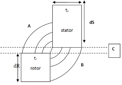
At aligned position, the air gap at C is 0.298mm. Hence, we assume that the space in between the two unaligned stator and rotor respectively are at 0.298mm from bottom of rotor to top of stator; and the space in between the right of rotor to the left of stator is also 0.298mm.
Figure-1. Idealized unaligned position of rotor relative to stator of 6/4 SRM.
Calculation of unaligned position, P2
Taking into account just 2 flux pathway at (A):
1. G2 =
2. G1= 0.4214( using solutions of triangle)
Calculation of aligned position, P1
Permeance calculation of irregular shaped 6/4 SRM using assumed flux pathway (AFP)
(a) (b)
Figure-2. (a) Aligned position of rotor relative to stator with actual stator tooth shape (b) Unaligned position of rotor
relative to stator with actual stator tooth shape.
The block model
For single-tooth per pole SRM, the block model is chosen to represent the following regions (Figure-1): a) Back-of-core
b) Stator pole c) Rotor pole d) Rotor body e) Air-gap
while the multi-tooth per pole SRM is represented by the following regions:
1. Back-of-core 2. Stator pole 3. Stator tooth 4. Rotor pole 5. Rotor body 6. Air-gap
Calculation of unaligned position, P2
Considering the dR is equal to tr, we can assume
that the air gap is equal to the horizontal position between rotor and stator. Thus;
At B, we take the radius at 0.1, 0.2 and 0.3
Considering flux pathway at A and C,
VOL. 1 1, NO. 1 4, JULY 2016 I SSN 1819 - 6608
ARPN Jour nal of Engineering and Applied Sciences
© 2006- 2016 Asian Resear ch Publishing Net w or k ( ARPN) . All r ight s r eser ved. www.arpnjournals.com
Analysis
Standard equations are used, as in reference 2 covering equations 1 to 8, starting from an initial value of flux-linkage (Ψ) and peak excitation current (Ip), the flux
density in part x of the magnetic current (Bx) is determined
by:
Or
, [1]
For each value of Bx, the corresponding value of
Hx is determined from the B-H characteristics of the core
material. Hence:
[2]
Therefore, the total MMF for y parts of the magnetic circuit can be calculated by:
[3]
where y is equal to total number of parts of the magnetic circuit being considered.
Equation [3] can be written in another form:
[4]
As stated in (2), to determine the correct value of Bx used in the calculation, the results obtained from
Equation [3] is compared with the value from Equation [4]. If │F-Fp│ is more than the acceptable limit, the
calculations are repeated again using the next value of Ψ. The value of Ψ is incremented at regular interval while Ip
remains the same. This iterative process is repeated until│F-Fp│ is within the acceptable limit.
Next, the value of Ip is set to another value and
the whole processes are repeated. Value of Ip is not
necessarily incremented at regular intervals. The end results will be tha value of Ψ for different parts of the magnetic circuits (within acceptable tolerance limit) corresponding to each value of Ip, (2).
Static-torque production
In SRM, the most general expression for instantaneous torque is
[5]
Where Wi is the co-energy defined as in Equation 5.
[6]
The electromagnetic energy that is available to be converted into mechanical work is equal to the area W. In one revolution each phase conducts as many strokes as there are rotor poles, so that there are qNr strokes or steps
per revolution. The average torque is therefore given by: Average torque = work per stroke x Number of strokes per revolution/2 ; or
[7]
The average electromagnetic power is converted
Pe = [8]
Where = speed in rad/sec. From this must be subtracted the friction, wind age (copper loss) and rotor core losses.
The above equations 1 to 8 are used to compute the 6/4 SRM under study.
Total mmf drop of the 6/4 SRM
The total mmf drop for the 6/4 SRM is equal to the summation of mmf at the air-gap, at the rotor teeth, stator teeth and the stator back-of core.
In concept, we know that:
From this, mmf drop at the air-gap can be expressed as
Mmf drop at the motor’s air-gap:
Mmf drop at the rotor and stator are based on the B-H curve of the material used.
Mmf drop at the back-of-core:
The computation is proceeded for complete flux linkage characteristics.
RESULTS AND DISCUSSIONS
VOL. 11, NO. 14, JULY 2016 I SSN 1819- 6608
ARPN Jour nal of Engineer ing and Applied Sciences
© 20 06- 2016 Asian Resear ch Publishing Net w or k ( ARPN) . All r ight s r eser ved. www.arpnjournals.com
Table-1. Unaligned position of rotor and stator.
Φ(m) HdR HdS Hg HBOC Mmf drop (At)
0.2 1.52 1.52 2771.92 8.41m 2774.97 0.3 3.18 3.17 4157.88 0.013 4164.25 0.4 10.17 10.16 5543.84 0.017 5564.19 0.5 127.07 126.94 6929.81 0.021 7183.84 0.6 762.41 761.65 8315.77 0.025 9839.86 0.7 2541.36 2538.82 9701.73 0.029 14781.94 0.8 17789.52 17771.74 11087.69 0.034 46648.98
Table-2. Aligned position of rotor and stator.
Φ(m) HdR HdS Hg HBOC Mmf drop (At)
0.2 1.52 1.52 157.04 8.41m 160.09 0.3 3.18 3.17 235.57 0.013 241.93 0.4 10.17 10.16 314.09 0.017 334.44 0.5 127.07 126.94 392.61 0.021 646.64 0.6 762.41 761.65 471.13 0.025 1995.19 0.7 2541.36 2538.82 549.65 0.029 5629.86 0.8 17789.52 17771.74 628.17 0.034 36189.46
Based on these values and equations 5 until 8, the motor performance can be calculated.
The closer the flux is to the centre of the initial point of calculation, the more it affects the relative value of the permeance. This is because as the flux pathway moves outward, the value becomes less as the magnetic strength reduces in proportion to the distance. This is proven via the calculation using the Assumed Flux Pathway (AFP) in which it proves that as the flux pathway moves outwards, the effects on the total permeance reduce. In terms of material used for the various parts of the motor, different components will derive a different value of mmf drops as in reference to the B-H curve for the particular material used. The total mmf drop for the Switched Reluctance Motor (SRM) is the summation of mmf drop at the air-gap, rotor-teeth, stator-teeth and the stator back-of-core. The computed data is expressed in a graph of Ampere-turn (A-t) against phi (ψ) with range of values from φi to φsat. 3-D leakage fluxes have a major effect on the performance of the SRMs. These leakage fluxes increase with the number of stator and rotor teeth. In addition, the percentage of the leakage flux relative to the total flux inside the motor varies in accordance to the aligned and unaligned positions of the rotor and stator. However, in the 6/4 SRM, the leakage permeance due to leakage flux between adjacent stator poles is small in comparison with the total air-gap permeance.
CONCLUSIONS
This research concludes that the concept of permeance can be incorporated in the analysis of the 6/4 SRM. The advantage of using this concept the non-linearity is maintained throughout the computation of the performance of the 6/4 SRM. This implies that more accurate performance of the 6/4 SRM can be computed compared to researchers using linearize model. The consequent torque characteristics computed can serve as a guide for comparison with equivalent induction motor. In this way the SRM can confidently be chosen as a candidate to help save energy in various applications, notably in water treatment plants, where the electricity bills on average amount to easily one million per month per plant. This saving is due to the inherent characteristic of SRM itself, that it is driven into high saturation region during operation.
REFERENCES
AHN, J.W.”Torque control in Switched Reluctance Motor”, Switched Reluctance Motor, Ph.D, Kyunsung University, Korea, pp 207-210.
VOL. 11, NO. 14, JULY 2016 I SSN 1819- 6608
ARPN Jour nal of Engineer ing and Applied Sciences
© 20 06- 2016 Asian Resear ch Publishing Net w or k ( ARPN) . All r ight s r eser ved. www.arpnjournals.com
Faiz, J.: “Computational methods for the design for multi-tooth-per-pole switched reluctance motors”, Ph. D. Thesis, University of Newcastle upon Tyne, UK, 1988.
Faiz, J. and Finch, J. W.:”Two-dimensional leakage flux estimation in switched reluctance motors”, IEE 4th Conference on Electrical Machines and Drives, Pub. No. 310, 13-15 Sept. 1989, pp 317-321.
Finch, J.W.: ”Magnetic permeance of aligned doubly salient structures”, Proceedings of IEE, Vol. 133, Pt. B, No. 6, November 1986, pp 365-366.
Harris, M. R., Hughes, A. and Lawrenson, P. J.: “Static torque production in saturated doubly-salient machines”, Proceedings of IEE, Vol. 122, No. 10, Oct 1975, pp 1121-1127.
Kentli, F. and Calik, H.: “Matlab-Simulink Data of 6/4 SRM with Static Data Produced Using Finite Element Method”, Acta Polytechnica Hungarica, Vol. 8, No. 6, 2011.
Krishnan, R., Bharadwaj, A. S. and Materu, P.N.: “Computer-aided design of electrical machines for variable speed applications”, IEEE Transactions on Industry Eectronics, Vol 35, Nov. 1988, pp 560-571.
Materu, P. and Krishnan, R.: “Estimation of switched reluctance motor losses”, IEEE-IAS Proceedings, Pittsburgh, PA, October 1988.
Metwally, H. M. B.:”Multi-tooth per pole variable reluctance motors and thier use as variable speed drives”, Ph. D. Thesis, University of Newcastle upon Tyne, UK, 1985.
Miles, A. R.: ”Design of a 5MW, 9000Vswitched reluctance motor”, IEEE Transactions on Energy Conversion, Vol. 6, No. 3, Sept. 1991, pp 484-491.
Mukherji, K. C. and Neville, S.: ”Magnetic permeance of identical double slotting”, Proceedings of IEE, Vol. 118, No. 9, Sept 1971, pp 1257-1268.
Omar., Y. and Tamjis M. R. ”Modified Frohlich Equation for Computation of Switched Reluctance Motors (SRMs)” Department of Electrical Engineering, University of Malaya.