OMNI DIRECTIONAL CONTROL ALGORITHM FOR MECANUM WHEEL
MOHAMAD ZUFRI BIN ABD RAHMAN
This Report Is Submitted In Partial Fulfillment of Requirements for the Bachelor Degree of Electronic Engineering (Computer Engineering)
Fakulti Kejuruteraan Elektronik Dan Kejuruteraan Komputer Universiti Teknikal Malaysia Melaka
UNIVERSTI TEKNIKAL MALAYSIA MELAKA
FAKULTI KEJURUTERAAN ELEKTRONIK DAN KEJURUTERAAN KOMPUTER
BORANG PENGESAHAN STATUS LAPORAN
PROJEK SARJANA MUDA II
Tajuk Projek : ………
Sesi
Pengajian : 1 3 / 1 4
Saya ……….. (HURUF BESAR)
mengaku membenarkan Laporan Projek Sarjana Muda ini disimpan di Perpustakaan dengan syarat-syarat kegunaan seperti berikut:
1. Laporan adalah hakmilik Universiti Teknikal Malaysia Melaka.
2. Perpustakaan dibenarkan membuat salinan untuk tujuan pengajian sahaja.
3. Perpustakaan dibenarkan membuat salinan laporan ini sebagai bahan pertukaran antara institusi pengajian tinggi.
4. Sila tandakan ( √ ) :
SULIT* *(Mengandungi maklumat yang berdarjah keselamatan atau kepentingan Malaysia seperti yang termaktub di dalam AKTA RAHSIA RASMI 1972)
TERHAD** **(Mengandungi maklumat terhad yang telah ditentukan oleh organisasi/badan di mana penyelidikan dijalankan)
TIDAK TERHAD
Disahkan oleh:
__________________________ ___________________________________
(TANDATANGAN PENULIS) (COP DAN TANDATANGAN PENYELIA)
Tarikh: ……….. Tarikh: ………..
OMNI DIRECTIONAL CONTROL ALGORITHM FOR MECANUM WHEEL
“I hereby declare that this report entitled Omni Directional Control Algorithm for Mecanum wheel is a result of my own work except for quotes that have been cited
clearly in the reference”
Signature : ………
Student Name : MOHAMAD ZUFRI BIN ABD RAHMAN
“I hereby declare that I have read this report and in my opinion this report is sufficient in terms of scope and quality for the award of Bachelor Degree of Electronic Engineering
(Computer Engineering) with honours.”
Signature : ………
Supervisor’s Name : DR.SOO YEW GUAN
v
ACKNOWLEDGEMENT
Alhamdulillah praise to Allah S.W.T. for that I have finally completed the final year project (FYP). I would like to take this opportunity to express my sincerest thanks to all who involved in assisting to complete my FYP report which is compulsory for all bachelor degree student of Universiti Teknikal Malaysia Melaka (UTeM) in order to fulfill the requirement for completing the degree. I would firstly express my deepest gratitude and sincerest thanks to my project supervisor, Dr. Soo Yew Guan for his guide, tolerance, support both mentally and physically which proved to be the most valuable interaction as supervisor-student in order for me to complete my FYP.
vi
ABSTRACT
vii
ABSTRAK
viii
CONTENT
CHAPTER CONTENT PAGE
PROJECT TITLE i
ACKNOWLEDGEMENT v
ABSTRACT vi
ABSTRAK vii
CONTENT viii
TABLE LIST xi
FIGURE LIST xii
CHART LIST xiii
GLOSSARY xiv
I INTRODUCTION
1.1 MECANUM WHEEL 1
1.2 PROJECT OBJECTIVE 5
1.3 PROBLEM STATEMENT 5
1.4 WORK SCOPE 5
1.5 REPORT STRUCTURE 6
II LITERATURE REVIEW
ix
2.2 BRUSHLESS DC MOTOR 10
2.2.1 Introduction 10
2.2.2 Stator 10
2.2.3 Rotor 12
2.2.4 Working Principle 12 2.2.5 Torque And Efficiency 14 2.2.6 Comparison Of BLDC With Other DC
Motor
15
2.2.1 Application 16
III METHODOLOGY
3.1 METHODOLOGY 18
3.1.2 Input Output Variables 18 3.1.3 Project Hardware And Software 19 3.1.4 PWM Multiplier Calculation 23 3.1.5 Process Flow Chart 24 3.1.6 Circuit Connection Block
Diagram
25
3.1.7 Programming Approach 26
3.1.8 Summary 27
IV RESULT AND DISCUSSION
4.1 RESULT 28
4.1.1 PWM Multiplier Value 28 4.1.2 Algorithm In MPLAB Coding 31 4.1.2.1 MPLAB Algorithm Coding Flow Chart 34
x
4.2.1 Unique Multiplier Variable For Each Motor
36
4.2.2 PIC PWM Multiplier 43
V CONCLUSION AND RECOMMENDATION 45
5.1 CONCLUSION 45
5.2 RECOMMENDATION 46
REFERENCE 47
APPENDIX A 59
APPENDIX B 54
xi
TABLE LIST
NO. TITLE PAGE
1 Comparison of BLDC with other motors 15
2 PWM multiplier percentage value for every degree 29
3 Algorithm in MPLAB coding 31
4 PWM Multiplier Table 36
5 Comparison between expected result and implementation result.
49
xii
FIGURE LIST
NO. TITLE PAGE
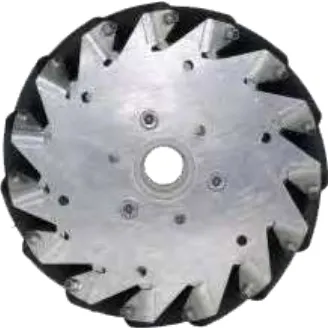
1 152mm Mecanum wheel 1
2 100mm Mecanum Wheel Design 2
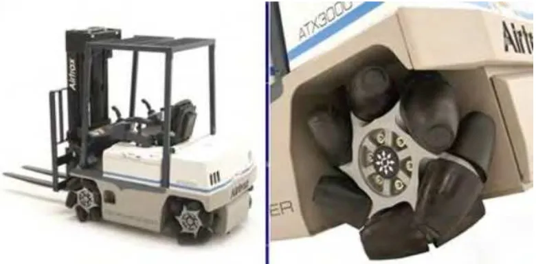
3 Mecanum Forklift 2
4 Tracked Wheel 3
5 Electric trolley with Ilon wheels 3
6 Basic Direction Control of Mecanum 4
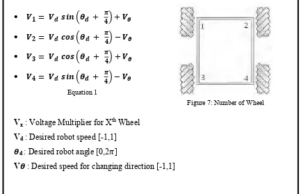
7 Number of Wheel 8
8 Laminated Steel Stampings - BLDC Stator 10
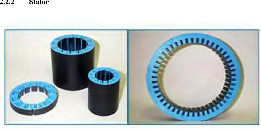
9 Slotted and Slot-less Motor 11
10 4 poles and 8 poles - Rotor 12
11 (A) Phase 1 13
12 (B) Phase 2 13
13 Speed – Torque - Power Curve 15
14 Input Output Block Diagram 18
15 PIC18F46K80 Pin Out 20
16 VEXTA Motor with driver 21
17 Lithium Polymer Battery 21
18 XCTU Hyper terminal Software 22
19 Connection Blok Diagram 25
xiii
CHART LIST
NO TITLE PAGE
1 Normalization process for motor outputs 9
2 Process Flow Chart 24
3 Complete flow of the algorithm. (MPLAB Coding) 35 4 Simplified version of algorithm process flow 38
xiv
GLOSSARY
DC - Direct Current
LCD - Liquid Crystal Display RPM - Revolution Per Minute
PIC - Programmable Integrated Circuit PWM - Pulse Width Modulation
1
CHAPTER I
INTRODUCTION
1.1 MECANUM WHEEL
Figure 1: 152mm Mecanum Wheel
2
Figure 2: 100mm Mecanum Wheel Design
This wheel is a conventional wheel but mounted with a series of small rollers around its circumference. This small rollers is mounted along the wheel rim with a shifted of 45° angle to the wheel plane. By switching the wheel right and left side rollers, the vehicle with the wheel can move at any direction when each of the wheels is applied with a varying speed and direction of rotation.[4]
Figure 3: Mecanum Forklift
3
bought the patent for the Mecanum wheel from Ilon and setup a research division to work on the wheel .This wheel is widely used in US aircraft carrier as it can provide a special movement for forklift in the carrier to maneuver in a tight space.
Figure 4: Tracked Wheel
There is another type of vehicle which using similar method for rotating around is the tracked vehicles. Usually, this tracked wheel is used by tanks and crane. Unfortunately, these vehicles will caused damage to the ground when they rotating around. This is caused by the track which has no roll able surface being drag as the vehicle rotate. The drag means high friction and high friction means, a lot of engine torque power are required to overcome the friction. By using Mecanum wheel, it is proven by the design which allowing a rotation to be done with a minimal friction thus required low torque engine which will reduce the cost of engine.
4
Mecanum wheel can be control by simply turn on and off a certain wheel to make the vehicle move to certain direction. However, this method only limited to a certain degree of direction. Figure 6 below is showing the direction that can be obtained from the method. [10]
Figure 6: Basic Direction Control of Mecanum.[10]
5
1.2 PROJECT OBJECTIVE
The objectives of this project are:
1. To study and analyze the speed of each DC Brushless motor needed in order to manipulate the Mecanum wheels for translating at specific degree of direction.
2. To construct algorithm for controlling each of the DC motor Speed and move the robot towards the desired angle of direction.
1.3 PROBLEM STATEMENT
The limitation of the robot movement using Mecanum by simply turning on and off the motor only enable the robot to move without changing it direction faced at 45°,90°,135°,180°,225°,270°315° and 360° only. To remove the angle limit, the speed and rotation direction of the Mecanum need to be manipulate. The difficulties faced in order to manipulate those variables are to calculate the speed required for certain angle translation, speed measuring and speed control in order to get the robot moving in the desired direction. This problem should be able to overcome by grouping each of the required tasks into a separate function and using a universal variable to hold the data.
1.4 WORK SCOPE
The work scope of this project is as listed below:
6
2. Calculate voltage multiplier for each motor to translate the robot at a certain angle.
3. Capture speed output signal from VEXTA Motor driver that is giving out a 30ms pulse signal for every complete rotation through interrupt input at microcontroller.
4. Display the motor output speed to LCD.
1.5 REPORT STRUCTURE
Chapter 1
This is discussing about the overall project development planning starting from the objective, problem statement until the methodology for the project. This Chapter is basically an overview from top to down of the project.
Chapter 2
This chapter is to show the literature review that has been made for studying the method to be used in developing the algorithm. The content came from sources from other researcher who already doing research about the Mecanum wheel movement characteristic.
Chapter 3
7
CHAPTER II
LITERATURE REVIEW
2.1 Mecanum Simplistic Control
From the research done by Ian McInerney from FRC Team 2022- First Robot Conference [2], mentioned that variables need to be considered:
o Desired Angle: What angle the robot needs to translate at
o Desired Magnitude: What speed the robot must move at
o Desired Rotation: How quickly to change the direction the robot faces
All the variables are to be identified whether to let it be a constant or adjustable (within the limit).
From the variables that have been identified, he comes up with the equation to manipulate those variables in order to obtain the PWM multiplier for each of the wheel motor.
8
Vx : Voltage Multiplier for Xth Wheel Vd: Desired robot speed [-1,1]
d : Desired robot angle [0,2 ]
V : Desired speed for changing direction [-1,1]
This equation consists of 2 parts where:
1. Force vector computation
(2.1)
2. Modification of rotation
The value for variable in those two parts can be modified using scalar quantity to adjust the rotation sensitivity. These equations will compute the voltage multiplier for the wheels, but they return a value which is between [-2, 2]. This range is larger than the desired range of [-1, 1]. The best way to fix that is to scale the outputs if any of them get above the desired range. This way the motors will travel at full speed in translation mode, but when rotation is commanded the outputs will scale to still be in the desired range of [-1, 1]. The process for scaling the motor outputs is shown in Chart 1.1.
9
Chart 1.1: Normalization process for motor outputs
Ian McInerney state that when using this algorithm to scale the motor outputs when they go outside rang [-1, 1] the ratio between the motor speeds is preserved, maintaining the desired final vector. This process also has the advantage that when full power is demanded in translation mode, the wheels will output full power, whereas if any of the values were to be modified using a scalar in the formulas in Equation 1, then full power would not be provided when commanded. [2]
Read Motor Voltage
Multiplier Value
Read Motor Voltage Multiplier Value
Read Motor Voltage Multiplier Value
No
Yes
Read Motor Voltage Multiplier Value
Read Motor Voltage Multiplier Value
No
10
2.2 Brushless DC Motor 2.2.1 Introduction
Brushless DC electric motor, BLDC, or known by the other name, electronically commutated motors have many similarities to AC induction motors and brushed DC motors in terms of construction and working principles respectively. Like all other motors, BLDC motors also have a rotor and a stator. BLDC electric powered synchronous motors. The DC electric source is supply from an inverter which produces an AC signal. The AC signal in this context means a bi-directional current without waveform restriction. There are sensors and controllers to control the inverter output.
2.2.2 Stator
Figure 8: Laminated Steel Stampings - BLDC Stator
![Figure 6: Basic Direction Control of Mecanum.[10]](https://thumb-ap.123doks.com/thumbv2/123dok/518278.59266/18.612.118.538.199.434/figure-basic-direction-control-of-mecanum.webp)