Master of Science in Manufacturing Engineering
Faculty of Manufacturing Engineering
OPTIMISATION OF CUTTER GEOMETRICAL FEATURE
FOR MACHINING ORTHOPEDIC, TRAUMA AND SPINAL
BIOMATERIALS IMPLANT
Nurul Husna Binti Mohd Nawawi
OPTIMISATION OF CUTTER GEOMETRICAL FEATURE FOR MACHINING ORTHOPEDIC, TRAUMA AND SPINAL BIOMATERIALS IMPLANT
NURUL HUSNA BINTI MOHD NAWAWI
A thesis submitted
in fulfillment of the requirements for the degree of Master of Science in Manufacturing Engineering
Faculty of Manufacturing Engineering
APPROVAL
I hereby declare that I have read this dissertation/report and in my opinion this
dissertation/report is sufficient in terms of scope and quality as a partial fulfillment of
Master of Science in Manufacturing Engineering.
Signature : ...
Name : DR.RAJA IZAMSHAH BIN RAJA
ABDULLAH
DECLARATION
I declare that this thesis entitled “Optimisation of Cutter Geometrical Feature for
Machining Orthopedic, Trauma and Spinal Biomaterials Implant” is the result of my own
research except as cited in the references. The thesis has not been accepted for any degree
and is not concurrently submitted in candidature of any other degree.
Signature : ...
Name : NURUL HUSNA BINTI MOHD NAWAWI
DEDICATION
ABSTRACT
ABSTRAK
ACKNOWLEDGEMENTS
First and foremost, I am so grateful to Allah S.W.T because given me strength and patience to completed this research. With His Merciful and Gracious, make me able to contribute idea and knowledge for this master thesis. I also thankful to my principal supervisor, Dr. Raja Izamshah Bin Raja Abdullah and my co-supervisor, Dr. Hadzley Bin Abu Bakar because always giving valuable advice, guidance and support for me to complete this study course.
My special thank goes to Dean of Centre of Graduate Studies, Associate Professor Dr. Zulkiflie Bin Ibrahim and Associate Professor Dr. Azizah Binti Shaaban , the former director of Center for Research and Innovation Management (CRIM) which providing financial support for my study through MyBrainUTeM scholarship.
My special appreciation also to Technician of CNC Laboratory , Mr. Hanafiah Bin Mohd Isa and Technician of CNC Tool Cutter Grinder Machine, Mr. Muhammad Helmi Bin Kahar as providing technical support and knowledge during my study.
TABLE OF CONTENTS
LIST OF ABBREVIATIONS x
LIST OF SYMBOLS xi
LIST OF PUBLICATIONS xii
CHAPTER
1 INTRODUCTION 1
1.1 Background 1
1.2 Advantage of PEEK in Medical Application 3
1.3 Medical Implant Fabrication Technique 4
1.4 Challenge in Machining PEEK Implant / Problem Statement 6
1.6 Objectives 8
1.7 Scopes 9
1.8 Thesis Organization 9
2 LITERATURE REVIEW 12
2.1 Introduction 12
2.2 Review of Polymeric Material 12
2.3 Polyetheretherketone (PEEK) 15
2.3.1 Characteristics of PEEK 16
2.3.2 Application of PEEK in Medical 19
2.4 Machining 21
2.4.1 Principle of Material Removal Process 22
2.4.2 Cutting Parameters 24
2.5 Machining Performance 31
2.5.1 Surface Roughness 32
2.5.2 Cutting Force 33
2.5.3 Chip Formation 34
2.5.3.1 Continuous Chip 35
2.5.3.2 Discontinuous Chip 36
2.6 Review of Statistical Technique used in Machining 37
2.6.1 Full Factorial 37
2.6.3 Response Surface Methodology (RSM) 40 2.6.3.1 Screening of independent variables 41 2.6.3.2 Selection of polynomial modelling 42 2.6.3.3 Fit polynomial function to experimental data 42 2.6.3.4 Evaluated of fitted polynomial function 43 2.6.3.5 Determination of optimal conditions 44 2.7 Review on Related Work in Machining PEEK Plastic 45
2.7 Summary 47
3 METHODOLOGY 49
3.1 Introduction 49
3.2 Method and Procedure 49
3.3 Experimental Setup 53
3.4 Fabrication of Carbide End Mill Tool 58
3.5 Experimental Design and Statistical Analysis 64
3.5.1 Taguchi Statistical Technique 64
3.5.2 Optimization with Central Composite Design (CCD) Technique
4.2.2 Macroscopic Observation 76
4.2.3 Summary of Screening Analysis 80
4.3 Response Surface Methodology Results 80
4.3.1 Cutting Force Result and Analysis 85 4.3.2 Surface Roughness Result and Analysis 97
4.3.3 Macroscopic Observation 109
4.3.4 Summary of RSM Analysis 111
4.4 Multiple Response Optimization Results 111
4.4.1 Validation Process 116
4.5 Summary of Multiple Response Optimization Analysis 120
5 CONCLUSION 121
5.1 Research Contribution 121
5.2 Recommendation for Future Work 123
LIST OF TABLES
TABLE TITLE PAGE
2.1 Type of polymeric materials 14
2.2 Mechanical and thermal Properties of PEEK 18 2.3 Machining guidelines for machining polymer 26
2.4 Explanation of terminology of end-mill 27
2.5 Evaluation on machining quality 31
2.6 Cutting performance of PEEK and testing method 32
2.7 Standard parameter of S/N ratio 40
2.8 Summary of author and finding related to PEEK machining 47 3.1 PEEK mechanical properties used in the experiment 54 3.2 Recommended machining parameter for PEEK 54 3.3 Machines, equipment and software used for the experiment. 55
3.4 Specification of carbide end mill 59
3.5 Machining parameters for grinding end-mill 63
3.6 L9 orthogonal array for four factors and three levels (34) 65
3.7 Coded values of 20 run of experiments by using CCD 66
4.1 Cutter parameter and level 70
4.2 Cutter and milling slot performed in the screening test 70 4.3 Experimental design using L9 orthogonal array 73
4.4 Analysis of Variance (ANOVA) 76
4.5 Cutter parameter and level 81
4.6 Cutter and milling slot performed for Tool No.1 to Tool No.6 82 4.7 Cutter and milling slot performed for Tool No.7 to Tool No.14 83 4.8 Cutter and milling slot performed for Tool No.15 to Tool No.20 84
4.9 Cutting force result 86
4.10 Sequential model sum of squares for cutting force 87
4.11 Lack of fit test for cutting force 88
4.12 ANOVA for response of cutting force 88
4.13 R-squared analysis for Response Surface Cubic model of cutting force
89
4.14 Surface roughness result 98
4.15 Sequential model sum of squares for surface roughness 99 4.16 Lack of fit test for surface roughness 100 4.17 ANOVA for Response of surface roughness 100 4.18 R-squared analysis for Response Surface Quadratic model of
surface roughness
101
4.21 Validation result combination of 16.20° rake angle, 30.21° helix angle and 10° clearance cutter geometry for resultant force
117
4.22 Validation result combination of 16.20° rake angle, 30.21° helix angle and 10° clearance cutter geometry for surface roughness
118
LIST OF FIGURES
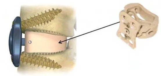
FIGURE TITLE PAGE 1.1 Orthopedic PEEK plate cage for cervical spinal bone 1
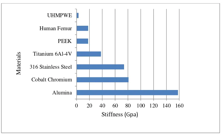
1.2 Stiffness property of implant materials compare with human femur bone
4
1.3 Production cycle of a patient–specific implant 6
2.1 Formation of PEEK by chemical reaction 17
2.2 Glass –transition temperature for polymer 18
2.3 Brantigan cage from PEEK material 20
2.4 (a) Morphology of bone cells cultured on Titanium disk plates b)Morphology of bone cells cultured on PEEK disk plates
21
2.5 Terminology of orthogonal cutting 23
2.6 Chip formation and shear in cutting zone 24
2.7 Structure and terminology end-mill 27
2.8 Mechanism of process damping 29
2.9 Indentation mechanism between tool and workpiece 29 2.10 Cutting force variation with different helix angle 30
2.11 Terminology of cutting force 34
2.12 (a) Continuous chip of Low Density Polyethylene (LDPE) material with elastic deformation and (b) Continuous chip of Low Density Polyethylene (LDPE) Polyethylene material with plastic
deformation
36
2.13 Discontinuous chip of thermosetting allyl diglycol carbonate 36 2.14 Figure 2.14: Type of response surface a) maximum b) plateau c)
maximum outside the experimental region d) minimum e) saddle
44
3.1 Flow chart of methodology 52
3.2 Experimental set-up for machining test. 54
3.3 The machine coordinate system. 59
3.4 Grinding wheels for ball nose end mill manufacturing. 60 3.5 External shape dimensions of ball-end mill 61
3.6 Section dimensions of ball-end mill 61
3.7 The cutting edge geometric model of the ball-end mill. 62 3.8 The gash out process for ball nose end mill 63 3.9 Example of the fabricated ball nose end-mill with variation in helix
angle.
63
3.10 Response surface design of CCD 66
4.1 Main effects plot for SN ratio of surface roughness 74
4.2 Chip and burr formation with Tool No. 2 77
4.4 Chip and burr formation with Tool No. 6 78
4.5 Chip and burr formation with Tool No. 9 79
4.6 High shear strain chip structure 79
4.7 Sample window of the acquired forces signal from DynoWare software
85
4.8 Diagnostic plots for cutting force, Ra: (a) Normal plot, (b) Residuals vs Predicted, (c) Predicted vs Actual
90
4.9 Interaction plot between factor on cutting force for (a) helix angle and rake angle, (b) clearance angle and rake angle, and (c) helix angle and clearance angle
94
4.10 3D response surface of resultant force for (a) rake angle and helix angle, (b)rake angle and clearance angle, and (c) helix angle and clearance angle
96
4.11 Surface roughness measuring location on each slot of milled surface.
97
4.12 Diagnostic plots for surface roughness, Ra: (a) Normal plot, (b) Residuals vs Predicted, (c) Predicted vs Actual
102
4.13 Interaction plot between factor on surface roughness for (a) helix angle and rake angle, (b) clearance angle and rake angle, and (c) helix angle and clearance angle
105
4.14 3D response surface of surface roughness for (a) rake angle and helix angle, (b)rake angle and clearance angle, and (c) helix angle and clearance angle
108
4.15 (a) to (d)Macroscopic observation of the machined surface 110
4.16 Location for macroscopic observation 111
4.17 Contour plot of the optimized desired responses 116 4.18 Graphical optimization of the optimized response 116 4.19 (a) Comparison of predicted to the actual validation for cutting
force and (b) Comparison of predicted to the actual validation for surface roughness
LIST OF ABBREVIATIONS
PEEK - Polyetheretherketone
PEEK CF30 - 30% Carbon Fiber Reinforced Polyetheretherketone
PEEK GF30 - 30% Graphite Fiber Reinforced Polyetheretherketone
HA - Hydroxyapetite
BMPs - Bone Morphogenic Protein
CT - Computer Tomography
CAD - Computer Aided Design
CAM - Computer Aided Manufacturing
RSM - Response Surface Methodology
DOE - Design of Experiments
ANOVA - Analysis of Variance
FEM - Finite Element Method
PCD - Polycrystalline Diamond
HDPE - High Density Polyethyelene
LDPE - Low Density Polyethylene
MMCS - Metal Matrix Composite
GFRP - Glass Fibre Reinforced Polymer
CCD - Central Composite Design
LIST OF SYMBOLS
µm - micro meter
°, ° C - degree, degree Celcius
Pa, Mpa - pascal, mega pascal
mK - meter kelvin
g/ - gram per centimetre cube
kg / - kilogram per meter cube
mm/ tooth - millimetre per tooth
mm/min - millimetre per min
mm/rev - millimetre per revolution
rpm - revolution per minute
% - percent
- tool -chip contact length
∅ - shear angle
Ra - arimethic roughness
n - number of samples
y, ӯ - measured data, average measured data
- Variance
- Null hypothesis
LIST OF PUBLICATIONS
1. R. Izamshah, N. Husna, M. Hadzley, M. Amran, M. Shahir, M. Amri,
Effects of Cutter Geometrical Feature on Machining Polyetheretherketone (PEEK)
Engineering Plastic, Journal of Mechanical Engineering and Sciences, 6,
872.
2. R. Izamshah, N. Husna, M. Hadzley, M. Amran, M. Shahir, M. Amri,
Determination on Effect of Cutter Geometrical Feature for Machining
Polyetheretherketone (PEEK) Using Taguchi Method, Applied Mechanics and
Materials, 699,pp.192-197. (SCOPUS Indexed)
3. R. Izamshah, N. Husna, M. Hadzley, M. Amran, M. Shahir, M. Amri,
Optimisation of Cutter Geometrical Feature to Minimise Force on
Polyetheretherketone (PEEK) Engineering Plastic, Proceedings of the 3rd
International Conference on Design and Concurrent Engineering (IDECON), 22-23
CHAPTER 1
INTRODUCTIONS
1.1 Backgrounds
Poly-ether-ether-ketone (PEEK) are thermoplastic polymer consisted of aromatic
ring structure bridging with ketone group and two ether linkages (Sagomonyants et al.,
2008). This structure gives stiffness, flexibility and toughness on this material. In addition,
its bio-compatibility to the human bodies has made it as an alternative material for medical
implant to replace metal based implant such as stainless steel and titanium alloy (Kurtz and
Devine, 2007). The increasing use of PEEK plastics can be seen in the development of a
wide range of orthopaedic applications, including spinal fusion cages, artificial discs and
femoral stems as shown in Figure 1.1.
for product parts. Incorporating plastic technologies (for example, injection molding)
means that the economics of production are viable on a larger scale, while complex shapes
can be formed as required to aid device fabrication. However, often for prototype designs
or short production runs such as patient specific implant, it is not economically viable to
manufacture injection molding tool. Under such circumstances, it is common to employ a
machining process on the PEEK polymer from a solid block material to form the
components.
However, the technique acquired from metal machining cannot be directly
transplanted to the polymeric material without considering the peculiar material response
on the cutting performances. Polymers are relatively soft if compared to metal and this can
create manufacturing problems related to machining. Machining performances such as
surface roughness, tool wear, part accuracy and cutting forces are directly affected by
several factors namely machining parameters, material properties, cutting tool geometry,
jig and clamping fixture. Above all the factors mentioned, cutting tool geometry is the
most crucial factor affecting the machining performances especially for polymeric material
(Shih et al., 2004). To the best of author’s knowledge, most of the latest cutting tools
geometry employed for machining PEEK were using the same cutting tool as metal
machining which can cause some problems. Severe tool wear and rough machined surface
were obtained during machining and finishing operations conducted on these polymeric
materials.
Surface roughness is a vital factor for medical implants since the cells of the
surrounding tissue interact with the underlying substrate on the micro and nanometer scales
(Krishna Alla et al., 2011). For some application, such as self-mating articulation cervical
the implant. The requirement for a fine surface roughness poses a major concern in
machining of polymeric base materials due to its low material of thermal conductivity.
The optimization of ball nose cutter geometry is purposely studied in this thesis.
The project involved a full collaboration with Medical Devices and Technology Group
(MediTeg), Faculty of Biosciences and Medical Engineering, Universiti Teknologi
Malaysia and funded by Malaysia Ministry of Education. The workpiece material is
Poly-ether-ether-ketone (PEEK) thermoplastic which are used for all of the components. The
milling process of PEEK thermoplastic for patient specific implants is generally employed
in medical practices. During milling process of this component, large volumes of materials
are removed with the risk of instability and tolerance violation. Traditionally, the cutting
tool geometry used in machining PEEK material are employed by a similar cutting tool
that cuts metal, which tends to lower the machining performances.
1.2 Advantages of PEEK in Medical Application
PEEK offers a lot of advantages compared to metal implant; biocompatible and
does not release metallic ions to human body which can trigger the allergic reactions in
certain patients. PEEK also able to withstand the corrosion in the human-biological
environment which is important to prolong the life span of implant (Ramakrishna et al.,
2010). In addition, it also offers greater strength, lightweight and translucent; which are
similar in properties with human bone. Like metal, surface coating technologies can also
be applied towards PEEK. For example, PEEK is coated with hydroxyapetite (HA) or
titanium which can be integrated with bone morphogenic protein (BMPs) to enhance the
with human bone. The correspond pattern of PEEK’s stiffness with bone elastic modulus at
16Gpa is imperative in reducing the stress shielding which can cause weakening of bony
region around the implants and ultimately lead to implant loosening (Green and Schlegel,
2001).
1.3 Medical Implant Fabrication Technique
In manufacturing production of conventional medical implants, a large scale of
injection molding and extrusion are involved (Kurtz, 2012). However, the main drawback
of this near shape process is that it only produced standard size implant. However, the
human bones are derived in many size and contour according to gender, age and ethnic.
Therefore, the reconstruction method during surgery needs to be carried out to fit the
standard- implant to human bones anatomy. However, the procedure is quite expensive and
time-consuming due to the abnormality of human joint-anatomy to be faced in the 0 20 40 60 80 100 120 140 160
(CAD) technology, the patient specific implant designs are emerging into the alternative
technique to solve the problem.
Patient specific implants are designed to customize a particular orthopedic patient.
It is produced through the integration of advance technique design based on Computer
Tomography (CT) scan data and machining process. The production of patient specific
implants started with the CT scan data containing of implant prescription by the surgeon.
Then, based on the CT scan data, manufacturer will reconstruct the design into a CAD
model and create the CAM code to generate the machine tool path. After the machining
process, the implants will be sterilized before being sent back to the hospital for
implantation (Fadda et al., 1998). One of the main advantages of using this procedure
isthat it can fit perfectly to the patient’s bone and reduce the complication due to the
reconstruction (Harryson et al., 2007). In addition, this technique is more sustainable in
terms of time and cost compared to the conventional implant procedure. Figure 1.3
1.4 Challenges in Machining PEEK Implant / Problem Statement
The machining of polymeric materials has been increasingly used and made
necessary when the quantity of precious items does not justify the cost of tooling for mould
or extrusion dies, or when a product needs a costly dimensional accuracy, such as polymer
implants. It is a well-known fact that machining of polymeric plastic can create several
problems due to its low thermal resistance, greater thermal expansion, low mechanical
characteristics and poor creep resistance. Too much heat input in the component can lead
to high stress levels and thus to warping or fracture. In addition, excessive heat input can
cause expansion of the plastic which make it difficult to control the required tolerances of
machined parts. On the other hand, inadequate fixation may lead to deformation during
conducted on these polymeric materials.
In the case of medical implants, fine surface roughness is a vital factor since the
cells of surrounding tissue interact with the underlying substrate on the micro and
nanometer scales. For some application, polymeric material like PEEK is promote better
cell bone growth compared to metallic materials like Titanium because PEEK’s surface
topography enhance implant - bone contact (Sagomontyant et al., 2008). Other medical
device, such as self-mating articulation cervical disc implants smooth surface finish is
critical so as to minimize the contact friction and wear. Nevertheless, the bone-cell
adhesions are directly related with the surface integrity of the implants. The requirement
for a fine surface roughness poses a major concern in machining PEEK implant materials.
PEEK’s does not dissipates heat easily and has low service temperature compared to metal.
PEEK can melt if the machining temperature increases above of the melting point (Fetecau
et al., 2008; Mata et al., 2009). PEEK also deform when the cutting force and shear stress
increases during machining which can lead to rough machined surface and inaccurate
tolerance of the implants.
Machining performances such as surface roughness, tool wear, accuracy and cutting
forces are directly affected by several factors namely machining parameters, material
properties, cutting tool geometry, jig and clamping fixture. Despite all of the factors,
cutting tool geometry is the most critical criteria affecting the machining performances
especially for polymeric material (www.sdplastics.com/pdf/machng.pdf access on 27
October 2013). To the best of author’s knowledge, most of the latest cutting tools geometry
employed for machining PEEK are similar to the cutting tool used for metal machining