Procedia Engineering 68 ( 2013 ) 305 – 312
1877-7058 © 2013 The Authors. Published by Elsevier Ltd.
Selection and peer-review under responsibility of The Malaysian Tribology Society (MYTRIBOS), Department of Mechanical Engineering, Universiti Malaya, 50603 Kuala Lumpur, Malaysia
doi: 10.1016/j.proeng.2013.12.184
ScienceDirect
* Corresponding author. Tel.: +6-06-234-6890; fax: +6-06-234-6884. E-mail address:[email protected]
The Malaysian International Tribology Conference 2013, MITC2013
Design Optimization of Thermal Management System for Electric
VehicleUtilizing CFD Analysis, DFMEA and CES
Noreffendy Tamaldin
a,b*, Ahmad Kamal Mat Yamin
a,b, Mohd Fadzli Bin Abdollah
a,b,
Hilmi Amiruddin
a,b, Mohd Azman Abdullah
a,baFaculty of Mechanical Engineering, Universiti Teknikal Malaysia Melaka, Hang Tuah Jaya, 76100 Durian Tunggal, Melaka, Malaysia bAdvanced Vehicle Technology Research Group, Universiti Teknikal Malaysia Melaka, Hang Tuah Jaya, 76100 Durian Tunggal, Melaka,
Malaysia
Abstract
Thermal management design for electric vehicles (EV) is very important in order to manage the thermal dissipated by operating components. This research aims at performing design optimization of a thermal management system for battery modules, controller and electric motor in EV. A combination of passive and active cooling systems is proposed where air cooled is used in battery modules, water cooling for controller and water jacket for electric motor. Design Failure Mode and Effect Analysis (DFMEA) method is deployed to identify the potential failure modes and causes so that improvements can be made for battery modules, controller and electric motor. The design for all of the components and the thermal management system were done with CATIA V5. The material selections process for the designs was based on the analysis using Cambridge Engineering Selector (CES EduPack). Final design was utilizing water cooled for electric motor and controller while using air cooled for battery modules. It was found that best material for electric motor and controller water jacket is with aluminum alloy 6060 while air cooled ducting using High Density Poly Ethylene (HDPE) and battery housing using Polycyclohexylenedimethylene Terephthalate (PCT). The thermal management system for battery modules is simulated using ANSYS CFD software. Results from simulation were validated with manual calculation and have shown good agreement based on the data collected at various vehicle speeds.
© 2013The Authors.Published by Elsevier Ltd.
Selection and peer-review under responsibility ofThe Malaysian Tribology Society (MYTRIBOS), Department of Mechanical Engineering, Universiti Malaya, 50603 Kuala Lumpur, Malaysia.
Keywords:EV thermal system design; CFD analysis EV; EV CES material analysis; DFMEAEV.
1.Introduction
Electric vehicles (EV) development has been reactivated due to concern over increasing fossil fuel demand and the environmental impact. EV is considered as zero emission since they did not require the use of fuel for propulsion thus emit no gaseous as end products. EV is expected to significantly reduce air pollution and as an alternative for replacing the current fuel powered vehicles. They also had drawn public attention and increasing number of consumer started to switch to EV rather than fuel powered vehicles. These can be observed by the total sales of worldwide EV which had hit the records and expected that the demands will continue to rise.
© 2013 The Authors. Published by Elsevier Ltd.
Automotive manufacturers had invested huge amount of money in research and development to manufacture their own electric vehicles. Example of commercialized electric vehicles presently in the market are like Nissan Leaf, Mitsubishi iMiEV, Toyota FT-EV, Citroen C-Zero, Tesla, Ford Focus electric and Chevrolet Volt electric car. Compared to internal combustion engines, electric vehicles offer several advantages such as improved energy efficiency, performance, environmental friendly and reduce the fossil fuel dependency. However, technologies in electric vehicles are not fully matured and still undergorapid development on the thermal management for battery modules, controller and electric motor. The main concern is still on the battery module since it is the heart of an electric vehicle [1-7]. Challenges in battery modules are such as recharging time, cost, vehicle driving range and cooling system.
1.1.Motivation of the study.
The main motivation for this study was initiated for the Proton Green Mobility Challenge 2012 (PGMC2012) in which UTeM took part alongside with ten other institutions of higher learning in Malaysia. In this event, a conventional vehicle powered by 4 cylinder internal combustion engine was utilized. The main task is converting the gasoline powered vehicle to a full electric vehicle to achieve the four main targets in this event including longest distance travel in a single charge; quarter mile acceleration; maximum velocity (V-max ); fastest time of two lap.The key factors considered in competing for the four events above are the thermal management design for the 3 main components involved in EV. The components are electric motor, motor controller and battery modules. The thermal management system needs to maintain certain temperature window for these components.
1.2.EV design for PGMC2012
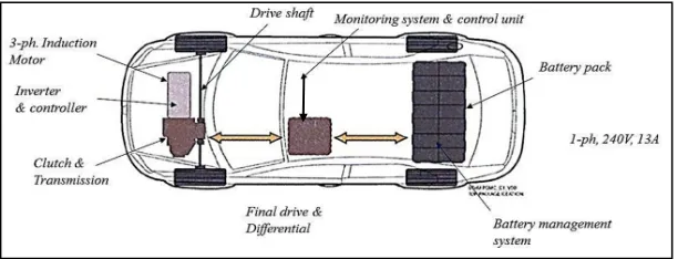
The initial design [7] was implemented in real vehicle without an in depth analysis due to time constraint in this competition. The development time involved in this competition was approximately six months. Therefore, this study was a continuation effort for the analysis to support the EV development. The configuration of the EV components was placed as shown in Fig. 1.
Fig. 1.UTeM EV design in PGMC2012.
2.Experimental procedure
the test vehicle. The new materials selected were incorporated into the new design and ANSYS CFD simulation package was utilized to analyze the performance of the new design with new materials. The validation process takes place by comparing the CFD result with theoretical.
3.Results and discussion
3.1.Preliminary test
The preliminary test was conducted to analyze the performance of the initial thermal management design in the real vehicle. A gradient road was used in these tests which include down-hill and up-hill accelerations. Thermocouples were place at various locations of the main components of EV in this test. The locations include the heat sink of the motor controller, the electric motor and the battery modules. The vehicle speed where the measurement takes place was up to 6000 rpm. In this test, only air cooled effect was monitored based on the vehicle speed.The summary of a sample reading is shown in Table 1.
Table 1.Operating temperatures from preliminary test
Locations Down-hill (oC) Up-hill (oC)
Motor Controller 30-40 30-60
Electric Motor 20-40 30-60
Battery Modules 20-40 30-40
3.2.Thermal System Design Strategy
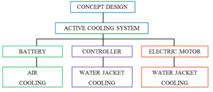
In addressing the thermal management design strategy, it is imperative to understand the temperature range of the component while in real time operation. Therefore the preliminary test, provide an early indication of the suitable design strategy needed for the three main components’ mention earlier. It was observed, the temperature window were within acceptable range (below 60 oC) while the vehicle is moving but increasing temperature were observed after the vehicle comes to a complete stop. Therefore, a combination of passive and active cooling strategies was recommended with air cooling for the battery modules and water cooling for the controller and electric motor. This design strategy is shown in Fig. 2.
Fig. 2. Design strategy of thermal management system for battery modules, controller and electric motor.
3.3.Final CATIA design, DFMEA analysis and Material Selection.
design activities to pursue next. It helps recognize the potential failure effects, the potential causes to the failure and the prevention methods. From this tool, it was observed that overheat was the major potential failure mode faced by all three components. DFMEA analysis shows that attention should be focus to the battery modules. Similarly, DFMEA analyses were performed for the motor controller and electric motor. The results show more potential failure modes, such as insufficient cooling air, faulty charging system and faulty installation. In this design, the focus is toward mechanical design therefore, potential electrical failure information was delivered to the electrical team for further action. Then, the electrical design constraints have been incorporated into the new design.Furthermore, electric motor may have problem associated with friction which may cause failure due to wear and tear as well as noise and vibration.
Information from DFMEA analysis was then supplied to the CATIA for design modification. As a result, new designs were proposed to enhance cooling flow for the battery modules, the electric motor and the controller. The existing design for air cooled ducting cause overheating due to low air velocity passing through. This is caused by saggy and corrugated ducting which disrupts the air flow. Therefore, low cooling efficiency was achieved with this design. The proposed new design provides smoother surfaces for smooth air flow with minimum resistance. Therefore better cooling efficiency was achieved. The differences between new and existing design for the battery air cooled ducting is shown in Fig.3.
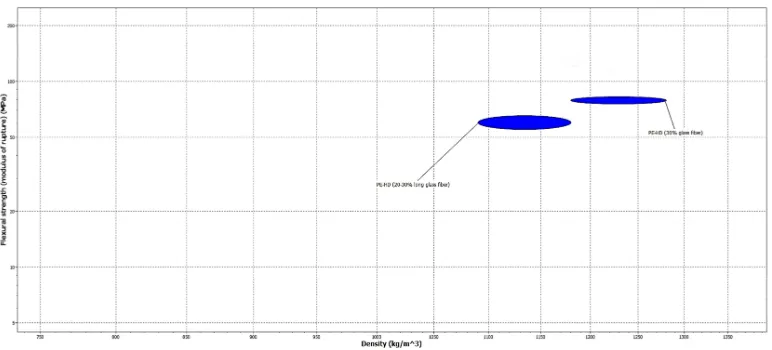
The material selection for the new design was further optimized using Cambridge Engineering Selector (CES). Results show better cooling efficiency and strength and high temperature resistance was achieved using HDPE as compared to PVC ducting. However, the cost increased dramatically utilizing this material which could be alleviate in high volume production. The HDPE properties is shown as the top right group in in Fig. 4 with the highest flexural strength.
Fig. 3.Design optimization for air cooled ducting of the battery modules.
Fig. 4.HDPE flexural strength versus density in CES for the battery modules air cooled ducting. HDPE (30% glass fiber on top right was chosen).
3.4.CFD Simulation and Validation Results
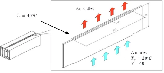
ANSYS Fluent Computational Fluid Dynamics (CFD) was used to carry out the analysis. CFD was used to determine the temperature distributions and outlet temperature of the designs. Several assumptions were made, such as uniform heat flux and temperature distribution, negligible thermal resistance, internal forced convection and steady stateflow at atmospheric pressure. For battery cooling system, the sample of analysis was the aluminum cooling channel plate located between the battery cells. Boundary conditions were applied with air inlet temperature of 20°C, air inlet velocity of 40 km/h, pressure: 1 atm (101 kPa),plate surface temperature of 40°C, convective heat transfer coefficient of 72.20 W/m2K and aluminum plate with dimensions of5mm × 110mm × 270 mm(w x h x l).The analysis region was the gaps of the plate, where the air is flowing through, as shown in Fig. 5.
Fig.5.Schematic diagram of battery plate cooling channel for analysis.
Fig. 6shows the temperature distributions across the inlet and outlet of the plate and Fig. 7shows the relative temperatures versus plate distance.
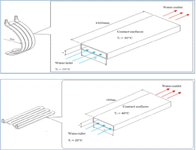
Similar procedures and assumptions have been applied for analysis of water jackets. For water jackets of electric motor and controller, both were treated as one meter straight ducts. Fig.8 shows the schematic diagram of electric motor and controller water jacket as assumed earlier.
Fig. 6. CFD result of battery plate. Fig. 7. Graph of relative temperature versus plate position.
ܶ௦ൌ ͶͲ°ܥ
ܶൌ ʹͲ°ܥ Air inlet
V = 40 Air outlet
Outlet
Fig. 8.Schematic diagram of electric motor and controller water jacket for analysis.
Fig.9. CFD result of electric motor and controller water jacket
Fig.10. Graph of relative temperature versus position for electric motor and controller water jacket
Fig.9 shows the temperature distributions across the electric motor water jacket represented in color gradient, while Fig.10 shows the relative temperatures versus length of water jacket. From the graph, it was observed that higher temperature encountered at the outlet of the water jacket, at 310 K or 37°C.
CFD validation were performed by computing the heat transfer coefficient; heat transfer rate per channel; air and water exit temperaturebased on the inlet temperature specified earlier. The heat transfer coefficient could be obtained from Reynolds number, friction factor (Petukhov equation) and Nusselt number. Table 2 and 3 summarized the air cooled and water cooled heat transfer rate and air exit temperature based on the three inlet temperature specified.
Outlet
Table 2. Summary of heat calculations for air cooled battery plate.
Table 3. Summary of heat calculations for water cooled of electric motor and controller.
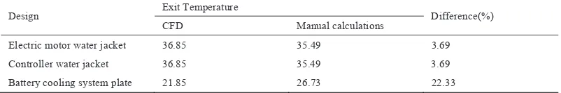
Finally, the comparison between ANSYS CFD tool were compared with the theoretical analysis and it was found to have close agreement. The differences for water cooled electric motor and controller theoretical analysis and CFD results were having close match within approximately below 5%. However, for the battery cooling system, the difference was below 25% and was noted for future improvement. The comparison between CFD results and theoretical calculation of the exit temperatures is shown in Table 4.
Table 4. CFD and manual calculations exit temperatures comparison
Design Exit Temperature Difference(%)
CFD Manual calculations
Electric motor water jacket 36.85 35.49 3.69
Controller water jacket 36.85 35.49 3.69
Battery cooling system plate 21.85 26.73 22.33
4.Conclusions
From the very beginning of the project, keys of designs were identified through information gathering and literature reviewing. Earlier conceptual designs were carried out through brainstorming method. During the design progresses, active cooling concepts were referred. The most goals - achieved designs were then chosen and proceed for drawing and drafting using CATIA. Both electric motor and controller employ water jackets as thermal management systems, while battery module employ outside air for its cooling system. Both analysis using ANSYS CFD and manual calculations were also performed. The exit temperatures from both results were compared and validated. Besides, the heat transfer rates for all three components are being calculated using equations. As the surface temperature of the component increases, the rate of heat transfer also increases. Material selections assisted by CES software shown that aluminium alloy 6060 T6 was suitable for the water jackets, HDPE material was suitable for the ducts while fire retardant PCT was suitable for the battery housing. From the analysis, new materials recommended perform better in terms of mechanical properties, thermal properties and durability. New materials used were cost half less than those used in PGMC, but the overall designs cost were expected to be higher since some additional components were added. Power consumptions need further improvements since some electrical – operated components were added. In conclusion, there were still rooms for improvement in term of power consumptions and overall designs cost. The thermal management systems have been successfully designed and the objectives of the project were achieved.
Acknowledgements
supports to complete this study.This research was supported by grant numbers [PJP/2012/CARE/Y00004, FRGS/2013/FKM/TK01/02/1/F00163, and RAGS/2012/FKM/TK01/1/B00001], as awarded by UniversitiTeknikal Malaysia Melaka (UTeM) and the Ministry of Higher Education Malaysia (MOHE).
References
[1] Alaoui, C., Salameh, Z.M., 2005.A Novel Thermal Management for Electric andHybrid Vehicles. Vehicular Technology, IEEE Transactions54, p. 468.
[2] Thermal Management Using Heat Sink. Application Note 185, March 2002.
[3] Broussely, M., 2002. Aging Mechanisms and Calendar-Life Predictions in Lithium-Ion Batteries, in “Advances in Lithium-Ion Batteries” W.A. Schalkwijk, B. Scrosati, Editor, Kluwer Academic/Plenum Publishers, New York, p. 393-432.
[4] Gross, O., Clark, S., 2011. Optimizing Electric Vehicle Battery Life through Battery Thermal Management, SAE International Journal of Engines, 4:1928-1943, 2011, doi: 10.4271/2011-01-1370.
[5] Hallaj, S. A., Selman, J.R., 2009. A Novel Thermal Management System for EV Batteries Using Phase-Change Material (PCM), J. Electrochem. Soc. Tgeg cv147 (9).
[6] Tamaldin, N., 2012. Development of Next Generation EV Thermal Management, Smart Automotive Climate Control, Dorint Pallas Wiesbaden Germany.