SUPERVISOR DECLARATION
“I hereby declare that I have read this thesis and in my opinion this report is sufficient in terms of scope and quality for award of degree of Bachelor of Mechanical Engineering
(Automotive).”
DESIGN AND FABRICATE PROPULSION
SYSTEM OF UTeM PERSONAL ELECTRIC VEHICLE (PEV)
OMAR BIN ROZANI
A report submitted in partial fulfilment of the requirements
for the award of the degree of Bachelor of Mechanical Engineering (Automotive)
Faculty of Mechanical Engineering Universiti Teknikal Malaysia Melaka
ii
DECLARATION
“I hereby declare that the work in this report is my own except for summaries and quotation which have been acknowledged.”
iii
iv
ACKNOWLEDGEMENT
First of all, I would like to thank Allah SWT for giving me strength to complete this project successfully on time. Then, I would like to express my deepest gratitude to my project supervisor, Dr. Muhammad Zahir bin Hassan who had continuously giving me guidance, ideas and support for this project. It would be difficult to complete this project without his support and understanding.
I would like to express the deepest appreciation to all my group members of Personal Electric Vehicle (PEV), Mohd Faisal bin Abdul Manas, Muhammad Aizuddin bin Othman and Muhammad Hazwan bin Md Jamal for all their guidance and help along this project. Their cooperation indeed too make my work become easier and faster. Thank you also to all my friends especially my course mate who involve directly or indirectly for this project.
I also would like to show my gratitude to thank my parents for their love, prayer, financial and never ending support, for the help in my training and for its success.
v
ABSTRACT
vi
ABSTRAK
vii
TABLE OF CONTENT
CHAPTER CONTENT PAGE
DECLARATION ii
DEDICATION iii
ACKNOWLEDGEMENT iv
ABSTRACT v
ABSTRAK vi
TABLE OF CONTENT vii
LIST OF TABLE x
LIST OF FIGURE xi
LIST OF LIST OF ABBREVIATIONS xii
LIST OF APPENDIXES xiv
CHAPTER 1 INTRODUCTION 1
1.1 Overview 1
1.2 Problem Statement 2
1.3 Objectives 2
1.4 Scopes 3
1.5 Expected Result 3
viii
CHAPTER CONTENT PAGE
CHAPTER 2 LITERATURE REVIEW 4
2.1 History of Electric Vehicle 4
2.2 Electric Vehicle 5
2.3 EV Motors 6
2.3.1 DC Motor 7
2.3.2 Series-wound Motors 8
2.3.3 AC Motors 9
2.3.4 Brushless DC Motors 9
2.3.5 Electric Wheelchair Motors 11
2.4 Efficiency 11
2.5 Battery System 12
2.5.1 Lead-Acid Batteries 12
2.5.1.1 The Absorbed Glass Matt 14
2.5.1.2 The Gel Cell 14
CHAPTER 3 METHODOLOGY 15
3.1 Introduction 15
3.2 Project flow 16
3.3 Design Consideration 18
3.3.1 Introduction 18
3.4 Development of vehicle model 20
3.4.1 PEV mathematical model 20
3.4.1.1 Tractive force 20
3.4.1.2 Aerodynamic force 21
3.4.1.3 Rolling resistance force 21
3.4.1.4 Hill climbing force 22
3.4.1.5 Acceleration force 22
3.4.1.6 Total tractive effort 22
3.4.1.7 Total amount of energy in PEV‟s fully charges batteries 23
ix
CHAPTER CONTENT PAGE
3.4.2 Modelling vehicle acceleration 25 3.4.2.1 Acceleration performance
parameter 25 3.4.2.2 Modelling the acceleration
of PEV 27
3.4.3 Small scale model 28
3.5 Analysis 29
3.5.1 Project implementation 29
CHAPTER 4 RESULT 31
4.1 Introduction 31 4.2 Effect of transmission efficiency 31 4.3 Effect of rider‟s weight 33 4.4 Effect battery energy 34
4.5 Road load 36
CHAPTER 5 DISCUSSION 37
5.1 Introduction 37 5.2 Transmission Efficiency 37 5.2.1 Hub motor advantages 38 5.3 Distribution of rider‟s weight 38 5.4 Distribution of battery‟s weight 39 5.5 Vehicle road load 39
CHAPTER 6 CONCLUSION AND RECOMMENDATION 41
6.1 Conclusion 41
6.2 Recommendation 43
REFERENCES 44
x
LIST OF TABLE
TABLE NO. TITLE PAGE
xi
LIST OF FIGURE
FIGURE NO. TITLE PAGE
2.1 Simple block diagram of electric Vehicle 5
2.2 Electric Vehicle System 6
2.3 Classification of EV motors 7
2.4 DC Motor 8
3.1 Concept flow chart 17
3.2 Three different arrangement of electric vehicle transmission 18
3.3 The force acting on a vehicle moving on a slope 20 3.4 Relationship between Torque and Force 26
3.5 Small scale model of PEV 29
3.6 Schematic diagram of PEV 30
4.1 PEV acceleration graph for 3 different type of transmission 32 4.2 Effect of traveller‟s weight to time travelled 33 4.3 Effect of traveller‟s weight to distance travelled 34 4.4 Effect of batteries energy to distance travelled 35
xii
LIST OF ABBREVIATIONS
AC Alternating Current AGM Absorbed Glass Matt DC Direct Current EV Electric Vehicle HED Hall Effect Device IC Internal Combustion
ICE Internal Combustion Engine PEV Personal Electric Vehicle PM Permanent Magnet
PMS Permanent Magnet Synchronous PMBDC Permanent Magnet Brushless DC PMH Permanent Magnet Hybrid PWM Pulse-Width Modulated SR Series Luctant
xiii
LIST OF APPENDIXES
NO. TITLE PAGE
A PEV mathematical modelling 48
1
CHAPTER 1
INTRODUCTION
1.1 OVERVIEW
The environmental argument as well as economical issues for electric propulsion becomes more compelling to develop clean, efficient, and sustainable vehicle for urban transportation. Automobiles nowadays is very important in our daily life, and the exhaust emission produce by conventional internal combustion (IC) engine vehicles are to be blame for the major problem of air pollution that cause the greenhouse effect leading to global warming.
For the last 10 years, the number of automobiles on our planet doubled to about a billion or so (Husain, 2003). The increasing of new automobile being introduced on road by car makers only contributes more on pollution problem.
2
Electric vehicle have no emission and have potential to control the pollution problem in an efficient way. Therefore, EVs are the only zero-emission vehicles possible for nowadays and future.
1.2 PROBLEM STATEMENT
The technology of electric vehicles has appeared since nineteenth century but decrease as the gasoline powered engine take over the attention. Nowadays, the future of electric vehicles is very bright. Their impacts are very significant ranging from economic, to new technology that can be applied elsewhere and most importantly, to the environment. Here are the problem statements for this study:
i. Mobility device ii. Green technology iii. Efficiency
iv. Eco design v. Affordability
1.3 OBJECTIVES
The objectives of this project are as follows:
i. To design and fabricate propulsion system of the first UTeM‟s Personal Electric Vehicle (PEV).
ii. To provide an optimized propulsion system for UTeM‟s PEV.
3
1.4 SCOPES
The scopes of this project are:
i. To conduct feasibilities studies on motor performance. ii. To study the efficiency movement of the PEV.
iii. To install and investigate the motor performance onto the UTeM-PEV.
1.5 EXPECTED RESULT
The project will result on development of the first UTeM‟s Personal Electric Vehicle (PEV). This PEV use electric bicycle motors and batteries that available in market as the propulsion method. The outcome of the project let to the development of the electric vehicle propulsion system.
1.6 THESIS OUTLINE
4
CHAPTER 2
LITERATURE REVIEW
2.1 HISTORY OF ELECTRIC VEHICLE
Electric Vehicles (EV) are not a new phenomenon. In fact, EVs have a history of over 100 years. They enjoyed much popularity between the mid-19th century and early 20th century, when electricity was the preferred method for propulsion.
The EV was silent, clean, and simple to operate. However, its range was limited by the charge of its batteries. Thus, EVs were restricted to areas where they could easily return home to recharge or where recharging facilities were made available by a local electric power company.
5
Subsequent advances in ICE technology and the invention of the electric starter negated this advantage; the greater range of gasoline cars, quicker refuelling times, and growing petroleum infrastructure, along with the mass production of gasoline vehicles by companies such as the Ford Motor Company (which reduced prices of gasoline cars to less than half that of equivalent electric cars), led to a decline in the use of electric propulsion, effectively removing it from the world‟s automotive market.
2.2 ELECTRIC VEHICLE
According to Leitman and Brant (2009), an electric vehicle consists of a battery that provides energy, an electric motor that drives the wheels, and a controller that sets the energy flow to the motor. Figure 2.1 shows the simple block diagram of electric vehicle.
6
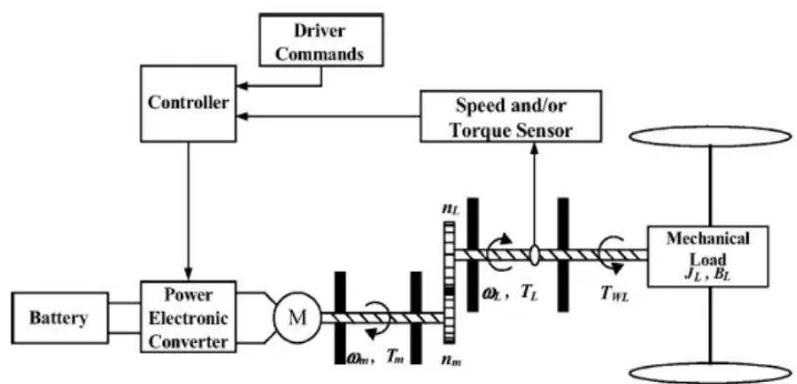
EVs are known as zero emission vehicles (ZEVs) and are much environment friendly than gasoline or LPG-powered vehicles. EVs have fewer moving parts and therefore the maintenance is minimal. EVs are also very quiet in operation and far more energy efficient than gasoline engines. EVs don‟t have ICEs in them. Instead, electrical energy is stored in a storage battery, converted from chemical energy in a fuel cell. This electrical energy is used to power an electric motor, which then turns the wheels and provides propulsion for the vehicle. In EVs, it doesn‟t burn fuel, so they don‟t produce pollution as ICE vehicles do.
EVs propulsion system consists of three major deviations which are batteries, electric traction motor and last one is gear train. These major deviations are dispersing in many significance ways such as vehicles performance, vehicles specifications, and many things.
Figure 2.2: Electric Vehicle System (Source: Ahmad Faiz, 2008)
2.3 EV MOTORS
7
Since the AC commutator motors have already been obsolete for EV propulsion, the DC commutator motors are loosely termed the commutator motors or simply the DC motors. The commutatorless motors can be further classified as two subgroups, namely the AC motors and the switched DC motors(Chau and Wang, 2005).
The AC motors include the induction motors, permanent magnet synchronous (PMS) motors, PM brushless DC (PMBDC) motors, and PM hybrid (PMH) motors, fed by sinusoidal, pulse-width modulated (PWM) or rectangular AC waveforms. The switched DC motors are mainly the switched reluctance (SR) motors which are fed by PWM or rectangular DC waveforms. Notice that the motor types encircled by round-corner boxes in Figure 1 have ever been used in EVs (Chau and Wang, 2005).
Figure 2.3: Classification of EV motors (Source: Chau and Wang, 2005)
2.3.1 DC Motor
8
DC motors is less reliable and unsuitable for maintenance-free operation because of the major problem of DC motors, due to their commutators and brushes. Nevertheless, because of improvement in technology and simple control, DC motors have been well-known in electric propulsion (Chau and Wang, 2005).
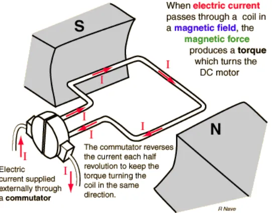
Figure 2.3 shows a diagram of simple DC motor. It consists of a loop of wire, a stationary magnet and the commutator. When current is passed through the loop of wire, it will cause a magnetic field formed in the wire. The loop of wire will align up with the field of the stationary magnet. Then the commutator is flips on the field every half rotation and this cause the loop to continually spin.
Figure 2.4: DC Motor (Source: diylive.net, 4 October 2010)
2.3.2 Series-wound motors
9
The series motor characteristic is particularly suitable for an electric vehicle as it gives excellent acceleration from rest combined with a controlled slowing down on hills and a constant high speed on the flat. Because of this reason and the fact that simple resistive and voltage controllers could be used, series-wound motors were widely used in electric vehicle from the early days onwards.
2.3.3 AC motors
Generally, there are three categories that the AC motor suitable for the use in electric vehicle: induction motors, synchronous motors and switched (or variable) reluctance motors (Westbrook, 2001). Induction and synchronous motors have been widely used for a long time in constant-speed industrial application. These types of motors become possible for electric vehicle use with the arrival of high power, high efficiency and variable frequency inverters.
All AC motors work on the same principle. A three-phase winding is distributed round a laminated stator and sets up the rotating magnetic field that the rotor „follows‟. The speed of this rotating field and hence the rotor can be calculated:
(2-1)
10
2.3.4 Brushless DC motors
A brushless motor operates much in the same way as a traditional brush motor. However, as the name implies there are no brushes (and no commutator). The mechanical switching function, implemented by the brush and commutator combination in a brush-type motor, is replaced by electronic switching in a brushless motor.
In a typical brushless motor the electromagnetic field, created by permanent magnets, is the rotating member of the motor and is called a rotor. The rotating magnetic field is generated with a number of electromagnets commutated with electronics switches (typically transistors or FETs) in a right order at right speed.
In a brushless motor, the trick becomes to know when to switch the electrical energy in the windings to perpetuate the rotating motion. This is typically accomplished in a brushless-type motor by some feedback means designed to provide an indication of the position of the magnet poles on the rotor relative to the windings. A Hall Effect Device (HED) is a commonly used means for providing this positional feedback.
In some applications brushless motors are commutated without sensors or with the use of an encoder for positional feedback. A brushless motor is often used when high reliability, long life and high speeds are required. The bearings in a brushless motor usually become the only parts to wear out.
In applications where high speeds are required (usually above 30,000 RPM) a brushless motor is considered a better choice because as motor speed increases so does the wear of the brushes on traditional motors.