THE SOURCE OF UNCERTAINTY IN 3D LASER SCANNER
Kamil, M.S., Kamely, A.M., Saifudin, H.Y., Puvanasvaran, A.P., Dan, M.M.P.
Faculty of Manufacturing Engineering Universiti Teknikal Malaysia Melaka (UTeM) Locked Bag 1752, Durian Tunggal Post Oice Durian Tunggal, 76109, Melaka, Malaysia
Author’s Email: [email protected]
ABSTRACT: 3D laser scanner become popular in manufacturing ield because of its capability in measuring various characteristics of part and reverse engineering. It is found that laser scanner which categorize under non-contact method is less accurate compared to the contact method. This is due to the output quality that depending on digitizing points captured during scanning. These digitizing points are afected from extrinsic and intrinsic parameters. Some of the parameters for commercial lasers are already calibrated prior to delivery. In this paper, extrinsic parameters are discussed based on LC15 laser scanner with Metris scan 4.1 sotware. A suggestion on model of uncertainty is suggested based on propagation of uncertainty method align with the understanding of extrinsic scanning parameters.
KEYWORDS: 3D laser scanner, Coordinate Measuring Machine, CCD.
1.0
INTRODUCTION
The capability of non-contact method in facilitating manufacturing processes is able to improve the competitiveness of most manufacturing company. This is driven by digitizing technique of products which later can be manipulated for measurement and reverse engineering. In general, the advantage of 3D laser scanner are able to perform full 3D
scan faster than the touch trigger probe although dealing with complex
components. The non-contact method approach able to prevent possible
deformation and scratches when deal with lexible or fragile materials.
However, in the case of Coordinate Measuring Machine (CMM), laser scanner is at least one order of magnitude less accurate compare to contact method touch trigger probe (Feng, et.al., 2001).
scanning paths and data manipulation of laser scanner. A diferent
approached is studied by Mekid and Luna (2007), whereby they stated that digitizing parameters contribute by the manufacturer and user are
directly afecting the accuracy of the laser scanner. This is also done
by Gastel, et.al. (2009) which study on the parameters of angle, scan depth and thermal stability test. They found that these parameters are
directly afecting the random and systematic errors. Mekid and Luna, (2007) divide digitizing parameters to two types that are extrinsic and intrinsic. Extrinsic parameters are parameters that can be controlled by
user while intrinsic parameters are not accessible by user.
In this study, the author classiied the digitizing parameters into three types which are easier to be identiied. Intrinsic parameters are come from
two sources that are; laser scanner and scan object characteristics. For laser scanner, intrinsic parameters is set and adjusted by manufacturer
which some of the parameters is stated in the technical speciication
of the product. These parameters are already calibrated before laser
scanner being used by users. For example, Metris the manufacturer of
laser scanner model LC 15 have mention parameters of depth of view
and stand of distance in their laser speciications. Non-contact method is known to be dependent on the quality of the relection which is other types of intrinsic parameters. For example, color of scan object, edges
and deep feature. These depended parameters give an option to the user in making planning and decision prior scanning. To overcome this issue, scanning technique can be used in minimizing the impact of
intrinsic parameters from scan object characteristics. For example, the
use of coating by using developer enables black and transparent objects to be detected by the laser sensor which introduced error.
In this paper, only extrinsic parameters for 3D laser scanner LC 15 manufactured by Metris are being considered. These extrinsic parameters are relying on Metris scan 4.1 sotware which facilitating the laser. Section 2 will explain about the source of uncertainty, Section
3 will discuss about uncertainty model suggested by the author and
Conclusion is followed in recapitulate the indings.
2.0
UNCERTAINTY IN LASER SCANNER
Mekid and Luna, (2007) classiied speckle noise, resolution, occlusion,
projected angle, deep features and edges as intrinsic parameters. Where intensity, distance between stripes, environmental conditions, warm
author based on the Metris Scan 4.1 sotware. These parameters are
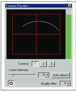
additional sources that listed by Mekid and Luna, (2007) and able to be set by the user. Figure 1 shows the illustration of the 3D laser scanner, LC15 manufactured by Metris.
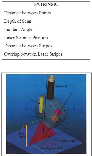
Table 1: Extrinsic Uncertainty Parameters EXTRINSIC
Distance between Points
Depth of Scan
Incident Angle
Laser Scanner Position
Distance between Stripes
Overlap between Laser Stripes
he Fracture part for Metris LC15. (1) Laser Module, (2) Mirrors, (3
μm and cannot be changed.
Figure 1. The Fracture part for Metris LC15. (1) Laser Module, (2) Mirrors, (3) Lens, (4) Filter, (5) Lens, (6) CCD Detector, (7) Housing, (8) PH10 interface with CMM. Others labeling are shown as scan of depth and ield of view that fall under laser parameters. The scanning direction, laser stripe and laser spot are just the properties of the laser
scanner (Luna, 2005).
2.1 Distance between points
Distance between points can be set prior scanning as shown in Figure 2. The minimum value for distance between points is zero (0) mm. Although the distance is set at minimum value, digitizing resolution
resolution for Metris LC 15 is stated by Mekid and Luna, (2007) to be 20 μm and cannot be changed. Digitizing resolution plays a role in
introducing error when the relection points do not fall at the feature
edges. This will cause either smaller or bigger size of scan objects. 2.2 Depth of Scan
Mekid and Luna, (2007) mentioned that the standof distance is the
distance between the output sources of the laser to the workpiece of the
measurand. They grouped it as extrinsic parameters. The author believe
that stand of distance is more appropriate to be selected as intrinsic
parameter. This is because, by referring Figure 1, standof distance is
including the distance between the laser source to the laser lens and the distance between laser lens to the surface of the workpiece. These
distances include the combination of intrinsic and extrinsic distances.
In this study, the author suggested depth of scan parameter is more suitable to be investigated since the parameter is totally dependent
on user seting thus,will be grouped under extrinsic parameters. With
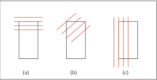
Metris 4.1, the depth of scan can be monitored from the camera preview dialog bog as shown in Figure 3.
Figure 2. The interface input for the value of points, stripe in Metris Scan 4.1.
ncident angle (α) is the angle of the laser from the laser planes to the laser position when perpendicular Figure 2. The interface input for the value of points, stripes and overlap
in Metris Scan 4.1.
2.3 Incident Angle
Incident angle (α) is the angle of the laser from the laser planes to the
laser position when perpendicular from the workpiece. The angle and
the seting increment of the angle is totally depends on the touch probe
Figure 3. The camera preview dialog box for fast review on t
angle (α), B = Scanner Position (δ)
shows three methods that can be used in manipulating the scanner position (δ) to perform a Figure 3. The camera preview dialog box for fast review on the distance
of scanner and workpiece.
10 Orientation, A = Incident angle (α), B = Scanner Position (δ)
shows three methods that can be used in manipulating the scanner position (δ) to perform a Figure 4. PH10 Orientation, A = Incident angle (α),
B = Scanner Position (δ)
2.4 Laser Scanner Position
Figure 5, shows three methods that can be used in manipulating the
scanner position (δ) to perform a scanning. This method is one of the
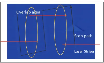
factors that studied in this project to investigate the probability of point detected at the edges of the workpiece. Although the author believed that the laser stripe and digitizing occlusions play an important role in detecting points especially at the edges, the scanner position can be used to manipulate these factors. It is believed, when angle is applied to the scanner position, the percentage of the laser scanner hit the edges of the component are higher. This is because, as shown in Figure 5(a) and Figure 5(c) the potential of the laser stripe miss the edges is high but in Figure 5(b), the percentage is minimum because in angle position. In
order words, it is a trade of factors that important to be investigated in
(a) (b) (c)
Figure 5. The laser stripe with diferent angle of laser scanner position. The angle is also depending on the interface of the laser scanner. In this project the interface of Renishaw PH10 is used. (a) The laser scanner in default position, 0° (b) The laser scanner at applied angle (c) The laser
scanner at vertical position, 90°.
2.5 Distances between Stripes
The laser light that hit the negative lens will be diverges and forms the laser stripe. Laser stripe moves on the surface of the workpiece and points is collected along the stripe. The points are registered by
the computer sotware in the form of cloud of points. This process is repeated based on the user input in the scan window seting to obtain
the desired surface scan as shown in Figure 2.
The seting by the user will determine the quality of the scan surface. Figure 6 represents an example of scanning seting of the distances
between stripes. This is because with smaller laser stripes distances, more points can be acquired. The vise versa will happen when the distances of stripes are increased. A close gap between distances will cause the increment of scanning time and slow speed scanning. Besides that, the distance between stripes can contribute to the detection
of edges features. For example, when the distances are small, the
potential in detecting the edges of a feature is grater than the use of
bigger distances of stripe seting. There should be a trade of in seting
Figure 6. (a) When deal with a plain surface without any features on it, the dista
Scan path
Laser stripe Overlap area
Laser Stripe
Figure 6. (a) When deal with a plain surface without any features on it, the distances between stripes can be increase for fast inspection. (b) The stripes between distances can be reduced for features scanning to
obtain the accuracy in inspection.
2.6 Overlap between Laser Stripes
The overlap means the coincident between laser stripes in time during scanning. When the path of the scanning direction is determined by the
user ater selecting the area needed to be scan as illustrated in Figure 7, the overlap seting will determine the distances that required for the
stripe to be overlap between one another. This will cause the volume of points increase at the area of intersection. This parameter is useful when certain feature is required to be in details.
Figure 7: The scanning path of laser scanner and the overlap area. The ov
Scan path
Laser stripe Overlap area
Laser Stripe
Figure 7: The scanning path of laser scanner and the overlap area. The overlap area is used to obtain the details in a certain scanning area.
3.0
MODEL OF UNCERTAINTY
U U U strp U d U p U o
2 2 2 2 2 2
1
Where δ = model of uncertainty, α1= incident angle, δ = scanner position, strp = distances between
(1)
Where δ = model of uncertainty, α1 = incident angle, δ = scanner position,
strp = distances between stripes, d = scan depth, p = distances between points, o = overlap between laser stripes.
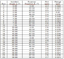
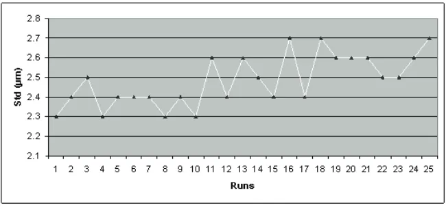
Table 2 can be used to understand the efect of these parameters in measurement. Based on the results, Figure 8, shows the efect of these
parameters during the calibration of laser scanner LC 15 by using a ceramic calibration sphere size of 15.014 mm. It shown that when the incident angle is increased, the standard deviation of the sphere
measurement is at high level. Further discussion on the efects of these
parameters in real measurement situation can be found in Kamil, S. and Mekid, (2009).
Table 2: Calibration result for Laser scanner at diferent angle.
Figure 8. The standard deviation value for the laser scanner for each calibration at diferent angle.
4.0
CONCLUSION
Non-contact methods are widely used in industries especially laser scanner because of the advantages against contact methods. It has
faster data collection, no delection contact with measurand and able
to produce 3D object for reverse engineering. However, it has lower accuracy compared to contact method. In this paper, discussion have
been done in encompass the extrinsic parameters that contribute the
level of laser scanner accuracy. It is found that incident angle plays an important role in determining the accuracy of the laser scanner although
there will be other factors efecting it. In overview, the other factors are contributed from CMM, the complexity form of the workpiece and
condition of the environment while the device is in used. A proper selection of parameters when using laser scanner LC15 is essential in
producing beter accuracy.
5.0
REFERENCES
Feng, H.Y., Yixin, L.; Feng Feng, X. (2001), “Analysis of digitizing errors of a laser scanning system”, Journal of the International Societies for precision and Nanotechnology 25, pp. 185-191.
Gastel, N.V., Cuypers, S., Bleys, P., Kruth, JP. (2009), “A performance evaluation test for laser line scanners on CMMs”, Optics and Lasers in Engineering, 47, pp. 336-342.
Kamil, M.S., (2007) “Dimension Inspection of Mesoscale Components Using Laser Scanner and CCD Camera’, (Msc Thesis), in Manufacturing Division, School of Mechanical, Aerospace and Civil Engineering, The University of Manchester, UK.
Luna, H.D,. (2005). “Investigation of Error Propagation in the Geometrical Inspection Using a CMM and Laser Scanner System”, (Msc Thesis), in Manufacturing Division, School of Mechanical, Aerospace and Civil Engineering, The University of Manchester, UK.