Oil and Gas Offshore Pipeline Leak Detection System: A Feasibility Study
M.F. Sulaima
1,a, W.M.Bukhari
1,b, F.A. Ali
1,c, M.N.M. Nasir
1,d, A.B. Yahya
1,e1
Faculty of Electrical Engineering, Universiti Teknikal Malaysia Melaka (UTeM), Hang Tuah Jaya, 76100 Malacca, Malaysia
a
[email protected], [email protected], [email protected], [email protected], e
Keywords: Pipeline Leak Detection System. Computational Pipeline Monitoring
Abstract. Pipelines leaks normally begin at poor joints, corrosions and cracks, and slowly progress to a major leakage. Accidents, terror, sabotage, or theft are some of human factor of pipeline leak. The primary purpose of Pipeline leak detection systems (PLDS) is to assist pipeline operators in detecting and locating leaks earlier. PLDS systems provide an alarm and display other related data to the pipeline operators for their decision-making. It is also beneficial because PLDS can enhance their productivity by reduced downtime and inspection time. PLDS can be divided into internally base or computational modeling PLDS Systems and external hardware base PLDS. The purpose of this paper is to study the various types of leak detection systems based on internally system to define a set of key criteria for evaluating the characteristics of this system and provide an evaluation method of leak detection technology as a guideline of choosing the appropriate system.
Introduction
Most of the fluids transported by pipelines are hazardous. This will impact on the human safety, pollution on the environment and production lost. Recent pipeline leak incidents have shown that the cost is much more than the associated downtime and clean-up expenses led to increasing awareness and concern for the environment. An effective and proper implementation of pipeline leak detection system will reduced spill volume and increased public confidence [1]. There are a numbers of oil spills issue that cause significant damage to the environment ecosystems, to property, to human life and very high financial loses. Leaks may occur because of many reasons; fatigue cracks, stress corrosion, hydrogen induction and ruptures [2].
Pipeline leak detection technologies can be categorized based on a variety of criteria. They vary from human visual inspections to hardware based sensors to the control systems based, real-time monitoring. Each approach has its strengths and weaknesses. The operational principle, data and equipment requirements, strengths, weaknesses, and the realistic performance limits (size, response time, location, false alarm, etc.) for the leak detection methods are addressed in this paper. Pipeline leak detection systems are varied and uniquely designed for each pipeline application. However, for discussion purposes, leak detection technologies can be classified according to the physical principles involved in the leak detection. Using this type of classification, general categories of leak detection technologies can be divided into the following two groups: Internally Based System and Externally Based System based on [3,4]. Computational Pipeline Monitoring (CPM) has categorized the groups of PLDS methods according to their inherent principle of leak detection as below.
Internally Base System
Based on [7], the Mass Balance Method is based on equation of conservation of mass. This technique identifies an imbalance between the incoming (receipt) and outgoing (delivery) volumes of mass. The volumes of product entering and leaving a pipeline are measured over a specified time period. The measurement results are expressed in terms of standardized volumes. The outgoing mass is subtracted from the incoming mass over the time period. A leak is suspected if the difference exceeds a threshold value. According to [8], the Pressure Point-Analysis (PPA) leak detection method is part of the pressure/flow monitoring method, which is based upon the statistical properties of a series of pressure or velocity pipeline measurements at one point being different before and after a leak occurs. The PPA method detects leaks by monitoring pipeline pressure at a single point along the line and comparing it against a running statistical trend constructed from previous pressure measurements contains evidence of a leak.
A sudden leak causes pipeline damage due to carelessly use of equipment, leads to negative pressure wave propagating at the speed of sound to both direction trough the pipeline. Such a wave can be recognised using installed high-sensitivity pressure transmitter, giving a leak alarm. It is also possible to calculate the leak location by timing interval of the pressure wave at two or more points on the pipeline. The technique called Wave Propagation method as reported in [9]. The leak position can be located if the moment T Downstream and T Upstream , when this negative wave passes the transmitter is measured.
In [10], an optimum sequential analysis technique (Sequential Probability Ratio Test) is applied to detect changes in the overall behavior of the inlet and outlet flow and pressure. It works based on the observation that although the control and operation may vary from one pipeline to another, the relationship between the pipeline pressure and flow will always change after a leak develops in a pipeline.
Externally Base System
The authors in [11, 12] were introduced distributed fibre optic sensing technique. Fibre optic is one of the promising leak detection technologies. Fibre optic sensors can be installed as distributed sensor. The cables will be attached and clamped to the pipeline, and utilize Distributed Temperature Sensor (DTS) method to detect the leaks. In [13],the leak detection in pipelines using acoustic emissions technology is based on the principle that escaping liquid creates an acoustic signal as it passes through a perforation in the pipe. Acoustic sensors affixed to the outside of the pipe monitor internal pipeline noise levels and
locations. These data are used to create a baseline “acoustic map” of the line. When a leak occurs, the
resulting low frequency acoustic signal is detected and analyzed by system processors. Deviations from the baseline acoustic profile would signal an alarm. The received signal is stronger near the leak site thus enabling leak location.
Key Consideration of PLDS Evaluation
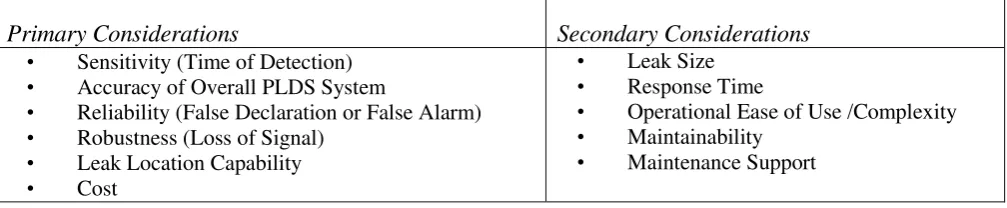
Table 1: Primary and Secondary considerations
Primary Considerations Secondary Considerations
• Sensitivity (Time of Detection)
• Accuracy of Overall PLDS System
• Reliability (False Declaration or False Alarm)
• Robustness (Loss of Signal)
• Leak Location Capability
• Cost
• Leak Size
• Response Time
• Operational Ease of Use /Complexity
• Maintainability
• Maintenance Support
A leak detection system is unique and depends on the pipeline locations, condition, types of fluids, pipeline size, length, operating parameters and instrumentation design. Key considerations criteria can be divided into two categories which is Primary and Secondary Considerations as shown in Table 1.
5-Very High , 4-High, 3-Moderate, 2-Low, 1-Very Low and 0-None. For better evaluation result, each criterion is weighted to different point base on priority and key criteria. This precise, measurable and quantifiable detail will determine the best technology. The best technology shall score highest rating in this technology evaluation.
Evaluation Result and Discussion
Table 2 represents the data and rating base on key considerations internally based (CPM) System leak detection methods in oil and gas industries while Table 3 shows the evaluation result.
Table 2: Internally Base System Comparison and Ratings [5,6,7,8]
Criteria
Compensated Volume Balance
Pressure/Flow Monitoring-
Pressure Point Analysis + Mass Balance
Rating : 5 (Very High)
Reliability (False Alarm declaration)
Free of nuisance alarm (compensated Volume balance) - depending on total accuracy.
Free of nuisance alarm with mass balance method for compensation.
Possible false alarm Free of nuisance alarm- with filtering
Rating : 0 (None) Rating : 3 (Average) Rating : 5 (Very High) Rating : 3 (Average) Rating : 5 (Very High)
Robustness (Loss of Signal)
Depending on the Flow meter robustness and accuracy
Yes, not depending on the flow meter.
Depending on the Flow meter, temperature and USD200K (Cost only on the hardware and software. Field instruments, engineering and installation are not included)
Approximately USD 440K (Price includes the hardware, software, 4 units of PT, 4 units of Flow meters, installation cost is excluded) USD340K (Cost only on the software and hardware. Field instruments, installation and engineering are not included)
Rating : 3 (Average) Rating : 3 (Average) Rating : 5 (Very High) Rating : 4(High) Rating : 3 (Average)
Ease of Pressure Transmitter
Software is
Rating : 3 (Average) Rating : 4 (High) Rating : 3 (Average) Rating : 4 (High) Rating : 3 (Average)
Response Time within 60 minutes From 5 minutes Within 9 minutes Within 60 minutes Within 60 minutes
Rating : 3 (Average)) Rating : 5 (Very High) Rating : 5 (Very High) Rating : 3 (Average) Rating : 3 (Average)
Maintainability Yearly calibration on the
field instruments.
Yearly calibration on the field instruments.
Yearly calibration on the field instruments
Maintenance Support
Yes Yes Yes Yes Yes
Rating : 5 (Very High) Rating : 5 (Very High) Rating : 5 (Very High) Rating : 5 (Very
High)
Rating : 5 (Very High)
Table 3: Evaluation result of Internally Base.
Selection Criteria
According to the evaluation process, the best rated PLDS method is RTTM (Real Time Transient Model) Method. This method is widely accepted, provide sensitivity to detect small leaks, detect
The architecture for the basic PLDS generally consist of three major elements: field instrumentation, a SCADA or RTU or PLC with associated software and telecommunications links. The sensors required for RTTM technique can be categorized as flow, pressure, and temperature. Flow meters are required at all inlets and outlets of the pipeline. Custody metering, i.e., the metering of flow necessary as the fluid
passes from one operator’s domain to another, thus serves a dual purpose. Pressure and temperature
sensors are required. Ideally these sensors should be distributed along the length of the pipe. The effectiveness of most of the PLDS software methods are depend on the sensitivity and accuracy of the field instrumentation especially the flow meter, thus it is critical to select the best performing flow meter. There appears a growing trend to utilize ultrasonic meter and coriolis mass meter for the crude oil metering application within oil and gas and Petrochemical Plants.
finalized. Fig. 1 shows the conceptual architecture design for offshore upstream pipeline leak detection system.
Fig. 1: Final Recommended Design for upstream PLDS
Summary
Internally based systems appear to offer future advantages. RTTM method is the best technology which scores the highest rating. The result and recommendation of this study result is focused on offshore upstream pipeline only. Future development and enhancement efforts on pipeline leak detection system method for oil and gas industry should be made. Major technology vendors shall play their role to develop new method or enhancement of existing method of pipeline leak detection systems A low-cost, sensitivity, accuracy, and reliability sshould be improve in developing new technology of PLDS. Combination of existing modeling with intelligent algorithm such as neural networks may offers better characteristic and advantages. For future work, this project can be improve by using simulation and detail calculation for each technology to prove the data given by each manufacturer of the technology.
References
[1] Sandberg, C. ; Holmes, J. ; McCoy, K. ; Koppitsch, H.: The application of a continuous leak
detection system to pipelines and associated equipment . (1989) Industry Applications, IEEE
Transactions.
[2] D. Harrold , “Do you know what's leaking?”, Control Engineering, vol 45, n 10, pp. 81-82,(1998)
Control Room
Field Control
Field Junction Box
Anttena for data transmission to BETA
RTTM Based Software PLDS System PC Receiver anttena
data submitted from ALPHA
Field Transmitter (Flow,
Pressure & Transmitter) Field Transmitter (Flow,
Pressure & Transmitter) Field
Junction Box
End of Pipeline at Platform Alpha End of Pipeline at Platform Beta
RT/PLC Panel
RT/PLC Panel Digital
Microcontroller Panel
PSU
Digital
Microcontroller Panel
PSU
Ethernet TCP/IP
Ethernet TCP/IP
[3] API 1130 (2007): Computational Pipeline Monitoring for Liquid Pipelines. 2nd Edition (September, 2007). American Petroleum Institute.
[4] PTS 31.40.60.1: Pipeline Leak Detection System, (September, 2002). PETRONAS Technical
Standard.
[5] Shouxi Wang, John J. Carroll (2007) : Leak Detection for Gas and Liquid Pipelines by Online
Modeling. SPE Gas liquids Engineering, June 2007
[6] Feng Jian, Zhang Huaguang (2004): Oil Pipeline Leak Detection and Location Using Double
Sensors pressure Gradient Method. Proceedings of the 5th World Congress on Intelligent Control and Automation, June 15-19, Hang Zhou, China.
[7] Geiger, G.; Matko, D.; Werner (2002), Leak Detection and Locating – A Survey. PSIG
0301(Pipeline Simulatrion Interest Group).
[8] Diane J Hovey, Edward J Farmer (2002): Pressure Point Analysis Leak Detection Methodology,
Performance and Application. EFA Technologies, AIChE Spring Meeting, March 2002, New Orleans, LA.
[9] Lijing Dong, Senchun Chai, Baihai Zhang, (2011) Leak Detection and Localization of Gas
Pipeline System Based on Wavelet Analysis. The 2nd International Conference on Intelligent Control and Information Processing, July 25-28.
[10] Zhang, X. J. (1993): Statistical leak detection in gas and liquid pipelines. Pipes & Pipelines
International, July- August 1993, p. 26-29.
[11] Information on www.sensornet.co.uk : Sensornet Group, Fibre Optic Digital Pipeline Leak
Detection – Application Guide.
[12] Großwig, S. et al. (2001): Distributed Fiber Optical Temperature Sensing Technique – A
Variable Tool for Monitoring Tasks. Proceedings of the 8th International Symposium on
Temperature and Thermal Measurements in Industry and Science, June 19 – 21, (2001).
[13] Information on www.wavealert.com :Acoustic Systems Incorporated : WaveAlert® VII Leak
![Table 2: Internally Base System Comparison and Ratings [5,6,7,8]](https://thumb-ap.123doks.com/thumbv2/123dok/550954.64756/3.595.51.565.213.800/table-internally-base-comparison-ratings.webp)


