Ahmad Zaki bin Hj Shukor, Yasutaka Fujimoto
Force Control of Musculoskeletal Manipulator Driven By Spiral
Motors
DOI UDK IFAC
10.7305/automatika.54-1.307 681.532-531.8:612.7; 531.1 3.2; 1.2.2
Original scientific paper
This paper presents force control of musculoskeletal manipulator driven by spiral motors. The kinematic and dynamic properties are shown to address the presence of ennvironmental contact with the manipulator. From this contact, the force control schemes were explored, by comparing between monoarticular-only structure and biarticular structure manipulator. Force control schemes were divided into independent muscle control, end effector step force command, and muscular viscoelasticity control. The results show advantages of biarticular actuation compared to monoarticular-only actuation in the feasibility of magnetic levitation (gap) control alongside force control.
Key words: biarticular muscle, force control, closed kinematic, parallel manipulator, muscular viscoelasticity
Upravljanje silom miši´cno-koštanog manipulatora pogonjenog spiralnim motorom. U ovome radu pred-stavljeno je upravljanje silom miši´cno-koštanog manipulatora pogonjenog spiralnim motorom. Kinematiˇcka i di-namiˇcka svojstva prikazuju prisutnost kontakta manipulatora s okolinom. Na temelju kontakta istraženo je up-ravljanje silom usporedbom jednozglobne i dvozglobne strukture manipulatora. Upup-ravljanje silom podijeljeno je u neovisno upravljanje miši´cima, upravljanje alatom manipulatora (eng. end effector) i upravljanje miši´cnom viskoelastiˇcnosti. Rezultati pokazuju prednost dvozglobne strukture u odnosu na jednozglobnu u smislu izvedivosti upravljanja magnetskom levitacijom pored upravljanja silom.
Kljuˇcne rijeˇci: dvozglobna struktura miši´ca, upravljanje silom, zatvorena kinematika, paralelni manipulator, miši´cna viskoelastiˇcnost
1 INTRODUCTION
Current implementation of mobile human-biologically-inspired robots can be seen in a variety of successful de-signs such as Humanoid Honda ASIMO [1], DLR robot arms [2], BigDog [3] and others. These designs have shown high manipulability, mobility, compliance and abil-ity to perform various tasks previously deemed as very difficult for a machine. The success is mainly attributed to the successful design and control of joint servo mo-tors at the hinges, i.e. elbows, shoulders, knees and an-kles. Although the use of joint servo motors is sufficient for current tasks, problems such as friction, backlash due to the use of gears and mechanisms are not negligible. Thus, researchers started venturing into direct drive actu-ators. However, the design of direct-drive joint actuators increases the weight of the motors.
A direct drive system for robotic systems, was reported in [4]. It avoids friction loss and realizes good controllabil-ity. Also, sensorless force control based on disturbance ob-server was shown in [5]. However, problems of mass and
volume of the robot arise (i.e. become large). Another sen-sorless force control of manipulator with geared robots was presented in [6]. The bandwith of the system was limited to gear friction. One of the solutions to improve force con-trol system was to combine accelerometer with disturbance observer [7] by enhancing sensing bandwith. Another so-lution was to implement a twin-drive system which cancels the static friction of the two geared motors via differential gear system [8]. Some actuators utilize elastic actuators between the output and gears [9] [10]. Although improving stability and safety, high frequency domain controllability is reduced.
pneu-matic muscles can be placed very near the skeleton struc-ture. However, the use of air supply could reduce mobil-ity. Also, fast and stable control of such actuators [15] is difficult to achieve compared to electrical motors. Some researchers use hydraulic actuators such as the HyQ robot [16] and exoskeleton XOS [17].
Some biarticular arm designs using electrical actua-tion have also been researched [18] [19]. In [18], the de-sign uses electrical motors alongside mechanisms (pulley, gears) to actuate monoarticular and biarticular actuators. As such, biarticular forces were viewed from joint angle perspective, without any closed-chain kinematics. Stiff-ness, feedforward inverse dynamics control was applied. For the Bi-Articularly Actuated and Wire Driven Robot Arm [19], the muscles were represented by wires for ac-tuation. By pulling or releasing the wires, 6 antagonis-tic muscles can be actuated using 6 servo motors. Force redundancy was solved using the infinity norm approach. In another research [20], virtual triarticular muscle control (with properties of AC motor control) was used to control the Lancelet robot (inspired from the ancestor of the ver-tebrae). The robot emulated swimming motion using the virtual triarticular muscle control.
Focusing on prismatic/translational/linear actuators, many works on PM linear synchronous motors have been reported. In [21], a high thrust density linear motor (HDL) has been proposed. HDL generates thrust force two times larger than linear induction motors. Tubular linear perma-nent magnet (TLPM) motors suggest practicality because of direct-drive motion and elimination of mechanical trans-mission losses [22]. An application example of TLPM is for drilling [23] and elevator door [24]. In general, by pro-viding current control in the stator of these motors, tube-shaped movers (with Permanent Magnets) are levitated and then direct drive motion can be realized.
Currently, in our laboratory, a new direct-drive transla-tional actuator, the spiral motor has been developed. The first prototype of a new spiral motor (of helical structure) which is direct drive, high backdrivable, high output ratio was shown in [25]. From the first prototype, the internal permanent version was developed and lately, the surface permanent magnet prototype [26] [27] for this research. The basic idea is that these spiral motors represent the mus-cles, one for each pair of antagonistic musmus-cles, i.e. one spiral motor for shoulder monoarticulars, one spiral mo-tor for elbow monoarticulars and one spiral momo-tor for the biarticular muscles. The reason behind this is because the spiral motor is a high force density, high forward and back-ward drivable actuator, i.e. equal forces can be applied in forward or reverse direction.
1.1 Research Focus
The monoarticular and biarticular muscles are retained in its linear form, by using spiral motors. In [28], we have shown some probable position control schemes of the biar-ticular manipulator. In this paper, the focus is to address force control on the biarticular manipulator structure at the end effector, and also apply muscular viscoelasticity control. The purpose of simulating different force control schemes is to estimate the feasibility and safety of mag-netic levitation of the spiral motor. Proper control will not only enable direct drive but also compliance.
1.2 Organization of Paper
This paper is organized as follows; Section 2 describes the geometrical analysis of the biarticular structure, Sec-tion 3 introduces the spiral motor, SecSec-tion 4 shows gap control on musculoskeletal configuration, Section 5 shows the biarticular dynamics model with environmental con-straints and Section 6 describes the force control schemes for the biarticular manipulator.
2 BIARTICULAR MUSCLE STRUCTURE
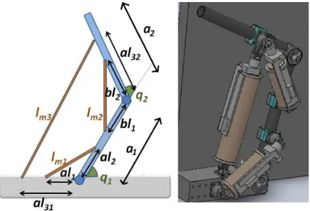
The human arm is an obvious biarticular structure, consisting of monoarticular and biarticular muscles at-tached to certain points of the arm bones. The combined flexor/extensor muscles of the planar manipulator of the biarticular structure is shown in Fig. 1. Based on Fig. 1 and using trigonometric identities, the relationship of mus-cle lengths,lmwith joint anglesqis derived as in (1).
Fig. 1. Biarticular structure (sketch and Solidworks model)
lm=
lm1
lm2
lm3
(1)
lm1 =
It is apparent that the extension or contraction of monoarticular muscles affect the respective joint angles to which they attach, i.e. muscle 1 affects the joint angleq1
and muscle 2 affects the joint angleq2. However, the
biar-ticular muscle 3 is redundant, because it affects both joint angles.
Based on (1) and (2), the relation between muscle ve-locity and joint veve-locity is given as in (3).
˙
lm=Jlmq q˙ (3)
where Jlmq is the Jacobian matrix between muscle and joint space and contains the following elements.
Jlmq=
Hence, the elements of the Jacobian matrix are derived.
∂lm1
Thus, the equation relating joint torques τ (vector of
q1andq2) and muscle forcesFlm(vector oflm1,lm2and
lm3) can be described.
τ =JlmqT Flm (6)
Also, the equation relating the joint torque and the end effector force,Fe(vector of cartesian forces) for a two link planar rotary manipulator is shown in (7).
τ =JT Fe (7)
whereJ is the Jacobian matrix from the task space to the joint space and contains the following elements.
−a1sin(q1)−a2sin(q1+q2) −a2sin(q1+q2)
a1cos(q1) +a2cos(q1+q2) a2cos(q1+q2)
(8) The relationship between the end effector forces and the muscle forces can be determined as follows.
Fe= [JT]−1 JlmqT Flmq (9)
One of the advantages of actuation redundancy of biar-ticular manipulator is the force ellipsoid, which is hexagon in shape, compared to tetragon for non-biarticular manip-ulators [29].
3 THE SPIRAL MOTOR
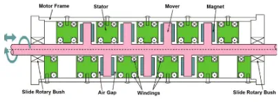
The spiral motor is a novel high thrust force actua-tor with high backdrivability, consists of a helical struc-ture mover and stator with permanent magnet. The mover moves spirally in the stator, and the linear motion is ex-tracted to drive the load. Thus, the motor realizes direct-drive motion. Moreover, the motor has high thrust-force characteristics because the flux is effectively utilized in its 3-D structure [25]. The illustration and assembled spiral motor are shown in Fig. 2 and Fig. 3.
Fig. 2. Spiral Motor Illustration
Fig. 3. Assembled Short-stroke Spiral Motor
Msx¨ = KfId+Kgxg−dx (10)
Jsθ¨ = KτIq−h(KfId+Kgxg)−dθ (11)
xg = x−hθ (12)
h = lp
2π (13)
Msx¨is the thrust of the spiral motor withMsas mass,
Jsθ¨is the spiral motor torque withJsas inertia,KfId is the force from d- axis current andKτIq is the force from q-axis current,Kgxgrepresents the force generated during magnetic levitation (xgis the gap between mover and sta-tor) andlpis lead length of screw. Gap displacementxg
is related to linear,xand angular displacement,θ. Linear and angular disturbances are labelleddxanddθ.
4 GAP CONTROL ON MUSCULOSKELETAL STRUCTURE
The direct drive control of spiral motors without attach-ing it to any structure has been shown previously in [27]. This was due to the success of maintaining two degrees of freedom control, which is magnetic levitation (gap) and rotational motion (θ) to realize forward and backward strokes. However, in the previous setup, the actuator is free to move without any constraints on the mover/stator attachments.
Fig. 4. Structure of musculoskeletal actuation: Shoulder monoarticular
In Fig. 4, we attach the 60mm stroke spiral motor to the manipulator configuration. Note the position of the mo-tor, which is intended to emulate monoarticular actuation. Gap control is essential in the direct-drive motion of the spiral motor because if motion is performed without gap control, there would be large frictional forces between the
mover and stator, The gap starts from touch down (con-tact with stator) offset position. Then magnetic levitation is performed so that stator and mover do not contact.
For vector control of spiral motor, the control variables for gap and angular terms are shown.
uxg = Kpg(xgref−xg) +Kdg( ˙xgref−xg˙ )(14)
uθ = Kpt(θref−θ) +Kdt( ˙θref−θ˙) (15)
The spiral motor thrust dynamics in terms of gap and angle are shown next.
Msx¨=Ms( ¨xg+hθ¨) =KfId+Kgxg−dx (16)
However, this time we will use only d-axis current to control the gap. Thus d-axis current reference can be de-rived by matching the gap control variable with the gap acceleration in the spiral motor dynamics (Mn,Kgn,Kτ n
are controller-assigned mass, gap constant, thrust constant values for spiral motor anddxgˆ is the gap disturbance esti-mation term).
Idref= 1
Kτ n(Mn(uxg)−Kgnxg+ ˆdxg) (17)
(a) Gap displacements (b) D-axis currents
Fig. 5. Gap levitation at -150 um offset
(a) Gap displacements (b) D-axis currents
Fig. 6. Gap levitation at -200 um offset
(a) Gap displacements (b) D-axis currents
Fig. 7. Gap levitation at -230 um offset
gap values within the stator are unknown, but can be esti-mated via linear and rotational sensors. Deformations can be caused from irregular surface of mover and/or stator.
The experimental results show that magnetic levitation was achieved for the monoarticular structure and the gap in the initial position of the actuator has at least 230µm space. In the results, the larger the initial gap offset value, the lesser d-axis current is required to maintain the gap at steady state. For direct drive motion (i.e. force or position control) combination of d and q-axis currents will have to be controlled simultaneously. This initial stage of gap sta-bilization is very important and experiments show the fea-sibility of gap control. Without stable gap control, magnets on the rotor will hit the stator blocks. Base on our expe-rience, too much collision and heat will cause the teeth of the yokes to be broken. The initial stage of force control in Section 6 prior to 0.5 s is magnetic levitation (gap) control.
5 BIARTICULAR DYNAMICS MODEL WITH EN-VIRONMENTAL CONSTRAINTS
For a two-link planar rotary manipulator, the dynamic equations of motion would incur the use of Ordinary Dif-ferential Equation of the following generalized form with
M as inertia/mass matrix,Cas Centrifugal/Coriolis,gas gravity terms,τas generalized torques/forces.
M(q)¨q+C(q,q˙) ˙q+g(q) =τ (18)
For a biarticular manipulator, due to its closed-kinematic chain, the dynamics would require an additional term [30] [31],λis Lagrange multiplier andJc is the Ja-cobian of the constraint equation(s) as shown in (19). This combined term is the vector of constraint forces.
M(q)¨q+C(q,q˙) ˙q+g(q) =τ+JT
c λ (19)
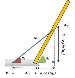
Firstly, the closed-chain system is virtually cut open at the connection point between the muscles (mover end) and the links. Then, the ’open-chain’ terms are derived using Lagrange-Euler formulation. The inertia matrix
Fig. 8. Illustration of Biarticular Constraints
Fig. 9. Biarticular Link Constraint in XY coordinates
Fig. 10. Monoarticular Link Constraint in XY coordinates
terms were obtained from the Jacobians and the Corio-lis/Centrifugal terms computed from Christofel symbols [32]. Gravity is ignored as this setup is intended to be in planar configuration.
Also, the relative acceleration at the constraint is zero (Jc is constraint Jacobian and Jc˙ is constraint Jacobian derivative),
Jcq¨+ ˙Jcq˙= 0 (20)
Unmentioned terms are zero.
The Jacobian time derivatives (Jc˙ ) of the constraints are derived by differentiating the constraint Jacobian with respect to time.
When the robot hits an environment, contact force,
JTFe will react with the end effector, and this contact
force is added to the dynamics.
M(q)¨q+C(q,q˙) ˙q=τ+JcTλ+JTFe (23)
Using (19) and (20), the dynamics of the structure can be represented as follows.
The contact forces shown previously include the Jaco-bian of the end effector, as in (8) and the cartesian forces,
Fe acting upon contact. To include the spiral motor dy-namics in the generalized closed chain model (24) has to be modified to the following.
The inertia terms from the angular rotation now emerges. With this modification, the d and q-axis currents could also be observed in the model. As an example, the size of the left-hand matrix becomes 17 (8 dof for biarticu-lar structure plus 3 dof from rotational part of spiral motor and 6 dof constraints). For the biarticular muscle, Js1to
Js3 show the inertia terms from three spiral motors, thus
the left hand terms of (25) can be expanded as shown.
and
¨
q1 . . . q¨8 θ¨1 θ¨2 θ¨3 λ¨1 . . . λ¨6
T
The right hand term of (25) can be expanded as shown.
tained by (28) and similarly for velocity and acceleration.
The environment interacting with the end effector could be represented in terms of impedance (with stiffness
Keand dampingDe).
Fe=KeXo+DeXo˙ (29)
Different environment will incur different values of stiffness and damping, i.e. stiffness of a concrete wall is greater than the stiffness of a rubber ball. The illustration of the biarticular structure in contact with the environment is shown in Fig. 11.
Fig. 11. Illustration of Biarticular Manipulator with Envi-ronment
6 FORCE CONTROL SCHEME FOR BIARTICU-LAR MANIPULATOR
Position control is sufficient for tasks which do not in-volve interaction with any objects or environment, for ex-ample spray-painting for cars in a factory line, and also workspace which has proper fence surrounding the robot (no human interference during operation). In the case of position control in the presence of environment, undesir-ably large forces would be applied as soon as the end ef-fector contacts the environment to overcome the obstacle in order to reach the desired trajectories designed.
In the presence of human, safe and compliant control is highly required to avoid damage to human/environment. This is important in human-robot interaction/co-operation. Small deviations in position are acceptable, as long as the forces are maintained not to exceed certain values (that could injur/harm human or environment), hence the term force control.
For a robotic manipulator, the forces that need to be controlled are the end effector or tool position. The biartic-ular manipulator would also require the end effector to be controlled in cartesian space and then the forces in carte-sian converted to forces in muscle actuation. Although the forces controlled are in the muscle domain, the equivalent virtual torques in the shoulder and elbow could be obtained by using the muscle to joint jacobian. This property is im-portant, because it does not make the control difficult, in-stead contributes to simplifications of the model.
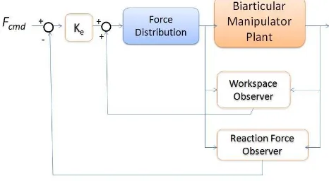
The force control scheme for the actuation-redundant biarticular manipulator could be represented as in Fig. 12. It can be seen that the force control scheme involves the use of disturbance observers to estimate the reaction forces in the cartesian domain. The cartesian velocities could be ob-tained from virtual joint velocities using conventional jaco-bian terms. Force reference command is labeled asFcmd, a vector of x-direction and y-direction force references. Ke
is the vector of force control gain for x and y.
In Fig. 12, force distribution block is shown in the con-trol. This is because the end effector forces (in x and y-direction) need to be converted to the muscle forces for shoulder monoarticular, elbow monoarticular and biarticu-lar muscle which will be tracked by muscle-level control. In short, the muscle forces are obtained by using the con-ventional jacobian transpose with the muscle jacobian, in other words, reversing (9).
Flmq= [JlmqT]−1 JT Fe (30)
Since the muscle jacobian is non-square, the Moore’s pseudo inverse matrix is used for inversion.
[JlmqT]−1= [Jlmq][JlmqT Jlmq]−1 (31)
Next, the workspace observer is designed. This is be-cause the measurable variables are from the spiral motors (linear and rotational displacements) and there are no en-coders on the elbow and shoulder joints. However, the an-gles can be calculated from the muscle kinematics shown earlier.
For the angle velocities, these can be obtained by the following equation.
Then the end effector position and velocities can be ob-tained via two-link forward kinematics and jacobian.
And end effector forces derived from muscle forces are again shown.
Then the estimated outputs of the workspace observer (x and y disturbance) can then be constructed.
ˆ
For the reaction force observer block, the same inputs are taken from the manipulator plant (i.e. muscle length, velocities). However, the outputs are slightly different than the workspace observer because it takes into account the estimated centrifugal/coriolis forces (C terms) as shown in the following equations.
ˆ
frx = fxˆ −C11(J11q˙1+J12q˙2) (40)
ˆ
fry = fyˆ −C22(J21q˙1+J22q˙2) (41)
Until this point, force control in taskspace was derived. However, these muscle forces will become reference forces for the muscle-level control to track. This is due to the equations of motion of the spiral motor. For the muscle-level control, the block diagram in Fig. 13 shows the over-all scheme. At this level, force tracking and gap control is performed simultaneously. Linear and rotational dis-turbance observers are estimated from the two degree-of-freedom plant model shown in (10) and (11). Dq-axis cur-rent references are generated to control the spiral motor actuation. The next step is d-q axis current tracking by the PI controller which is fed into the three-phase Permanent Magnet spiral motor (shown as 2 dof Spiral Motor plant). The power used for driving the manipulator structure can be obtained from the d- and q-axis currents because the spiral motor is a Permanent Magnet motor. Accordingly energy utilized can be obtained.
Fig. 13. Force Control Scheme for a Spiral Motor
The reaction force observer is almost similar to linear mo-tion disturbance observer but added with a constant fricmo-tion termDxwhich is arbitrarily chosen.
ˆ
dx = gx
s+gx(Kf nIdref+Kgxg+gxMnx˙)−gxMnx˙
ˆ
dθ = gθ
s+gθ(KτIqref −h(KfId+Kgxg) +gθJnθ˙)
−gθJnθ˙ (42)
The difference between force control for the conven-tional two-link manipulator and force control for the biar-ticular manipulator is the muscle Jacobian term. If the number of muscles used is multiplied, computational cost of the muscle Jacobian will increase. For example, struc-tures with 6 muscles from the shoulder to the elbow would incur heavier computation than 3 muscle structure.
6.1 Independent Muscle Control
For independent force control of each muscles, the in-teraction with the environment will be investigated. The initial position of the end effector was set at(0.15,0.53)m. The environment is set at x-position of 0.16. Stiffness and damping values of the environment are 3000 and 20. Al-though these parameters are set, the disturbance observer force control scheme is robust and can work in unknown or unstructured environments as well. Simulation is per-formed in two types of structure; structure with monoar-ticular muscles only and structure with monoarmonoar-ticular and biarticular muscles. Force commands were set at 10 N at
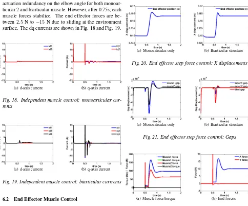
t= 0.5s for each muscles. Beforet= 0.5s, the gap mag-netic levitation is realized. The detail description of force control for spiral motors can be referred to in [33]. Com-parison between the x trajectories of both structure can be seen in Fig. 14 while gap responses are shown in Fig. 15.
(a) Monoarticular-only (b) Biarticular structure
Fig. 14. Independent muscle control: X displacements
It can be seen that collision between monoarticular-only manipulator and the environment occurs att= 0.68s
while the biarticular manipulator collides with the environ-ment faster, att= 0.60s. This is due to the additional
actu-(a) Monoarticular-only (b) Biarticular structure
Fig. 15. Independent muscle control: Gap displacements
ation from biarticular muscle which induces faster perfor-mance. However, the gap responses of the biarticular mus-cle vary relatively larger than monoarticular gap responses (red line in Fig. 15).
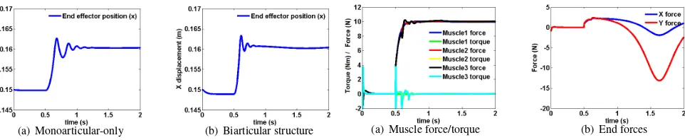
Fig. 16 shows the muscle forces and end effector forces for the monoarticular structure.
(a) Muscle force/torque (b) End forces
Fig. 16. Independent muscle control: forces for monoar-ticular
The force control of independent muscles was succes-fully achieved in the monoarticular structure. The end ef-fector forces vary between 1.5 N to−4.5 N because the end effector position changes (slides).
(a) Muscle force/torque (b) End forces
Fig. 17. Independent muscle control: biarticular forces
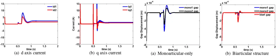
actuation redundancy on the elbow angle for both monoar-ticular 2 and biarmonoar-ticular muscle. However, after 0.75s, each muscle forces stabilize. The end effector forces are be-tween2.5 N to−15N due to sliding at the environment surface. The dq currents are shown in Fig. 18 and Fig. 19.
(a) d-axis current (b) q-axis current
Fig. 18. Independent muscle control: monoarticular cur-rents
(a) d-axis current (b) q-axis current
Fig. 19. Independent muscle control: biarticular currrents
6.2 End Effector Muscle Control
Using the same initial position and environmental pa-rameters, the muscle forces are indirectly controlled by the end effector forces in the cartesian domain. Initially, the end effector force in proper direction is given to ensure that the end effector hits the environment. After contacting with the environment, the forces are controlled to maintain end effector forces in the x-direction.
The force reference in the x-direction is given as 10 N and force reference for y-direction is 0 N. X-direction tra-jectory is shown in Fig. 20 and its gap responses depicted in Fig. 21.
Collision for biarticular structure occurs faster than monoarticular structure. The forces for the monoarticular-only structure is shown in Fig. 22.
As seen in Fig. 22, the end effector forces in x-direction were tracked, initially with overshoot. Also, y end forces are maintained at 0 N. This is achieved by monoarticular 1 (shoulder) force of 100 N and lesser force of 60 N from monoarticular 2 (elbow) muscle.
(a) Monoarticular-only (b) Biarticular structure
Fig. 20. End effector step force control: X displacements
(a) Monoarticular-only (b) Biarticular structure
Fig. 21. End effector step force control: Gaps
(a) Muscle force/torque (b) End forces
Fig. 22. End effector step force control: Monoarticular forces
For the biarticular structure case, as shown in Fig. 23, the end effector forces were also tracked successfully with the biarticular structure settling faster than the monoartic-ular structure. However, there were overshoots in the x-direction force and fluctuations in the y-x-direction force dur-ing collision. After collision, both forces stabilized with x force at 10 N and y force at 0 N. The main advantage of the biarticular manipulator compared to monoarticular ma-nipulator is the reduced muscle forces required to track the force command. The existence of biarticular muscles re-duces the effort of the elbow monoarticular muscle.
(a) Muscle force/torque (b) End forces
Fig. 23. End effector step force control: biarticular forces
(a) d axis current (b) q axis current
Fig. 24. End effector control: monoarticular currrents
(a) d-axis current (b) q-axis current
Fig. 25. End effector control: biarticular currrents
6.3 Muscular Viscoelasticity Control
The control goal of this part is to assess the spiral mo-tor redundant-actuamo-tor performance in the case of muscular force control. This control scheme is to emulate muscular viscoelasticity [34] by applying the following force com-mand;
fcmd = (ue−uf)+(ue+uf)(Km(x
0−x)−Dmx˙) (43)
whereueanduf are contractile force of virtual exten-sor and flexor muscles respectively. KmandDm values are set as10%of the environmental values. Due to the abil-ity of the spiral motor to generate both pulling and pushing force, a single spiral motor is sufficient to emulate an an-tagonistic muscle pair.
Linear and gap displacements for monoarticular-only structure and biarticular structure can be seen in Figures
(a) Monoarticular-only (b) Biarticular structure
Fig. 26. Musculoviscoelasticity control: X displacements
(a) Monoarticular-only (b) Biarticular structure
Fig. 27. Musculoviscoelasticity control: Gaps
26 and 27. For the monoarticular structure, the force re-sponses are shown in Fig. 28.
(a) Muscle force/torque (b) End forces
Fig. 28. Musculoviscoelasticity forces: monoarticular
From the force responses of monoarticular muscles (Fig. 28), the muscular viscoelasticity tracks the force successfully, with overshoots. This is done by forces of monoarticular muscles of around 30 N for monoarticular 1 (shoulder) and 20 N for monoarticular 2 (elbow). Y-Force was also stable at 0 N towards the end.
(a) Muscle force/torque (b) End forces
Fig. 29. Musculoviscoelasticity forces: biarticular
(a) d-axis current (b) q-axis current
Fig. 30. Musculoviscoelasticity currents: monoarticular
(a) d-axis current (b) q-axis current
Fig. 31. Musculoviscoelasticity currents: biarticular
To demonstrate that our controller is robust even with varying gains (or unknown environment parameters), we will show the musculoviscoelasticity control results with variations of Km and Dm with 0.2%, 30%, 200% and 400%. In all cases (refer Figs 32 and 33), the biarticular structure could track the force references.
6.4 End effector control with varying force reference
This section investigates the effect of varying fre-quency of force reference for the musculoskeletal manip-ulator. Force reference was generated using sinusoidal waveform with increasing frequency. We extend the simu-lation time from 2 seconds to 10 seconds. Fig. 34 shows the end effector x displacement. The changing position of the object is due to sinusoidal force command shown in Equation (44) (withAas the force magnitude).
fcmd=A(0.5(1−cos 2πt2
)) (44)
(a) Force tracking at 0.2% (b) Force tracking at 30%
Fig. 32. Musculoviscoelasticity forces at 0.2% and 30%: biarticular
(a) Force tracking at 200% (b) Force tracking at 400%
Fig. 33. Musculoviscoelasticity forces at 200% and 400%: biarticular
(a) Monoarticular-only (b) Biarticular structure
Fig. 34. Varying force reference: X displacements
As seen in Fig. 35, the gaps were maintained within limits for both monoarticular and biarticular structure. Monoarticular structure shows larger oscillations com-pared to biarticular.
(a) Monoarticular-only (b) Biarticular structure
For muscle forces used to track the end effector (re-fer Fig. 36), larger forces were required for monoarticular structure than biarticular (refer Fig. 37). Also, monoartic-ular end effector hits the environment several times as seen in the sparks in end effector forces.
(a) Muscle force/torque (b) End forces
Fig. 36. Varying force: monoarticular structure forces
At low frequencies, force reference was tracked succes-fully. But as frequencies increases, the manipulator could not achieve the desired force but tracks the forces with slightly lower force magnitude.
(a) Muscle force/torque (b) End forces
Fig. 37. Varying force: biarticular structure forces
D-axis current of biarticular manipulator (refer Fig. 39) shows lower magnitude than monoarticular manipulator d-axis current (refer Fig. 38).
(a) d-axis current (b) q-axis current
Fig. 38. Varying force: monoarticular structure currents
7 SUMMARY
This paper addresses force control of musculoskele-tal manipulator in the presence of environmenmusculoskele-tal contact.
(a) d-axis current (b) q-axis current
Fig. 39. Varying force: biarticular structure currents
By using disturbance observers designed in workspace and muscle-space, force control were simulated in three differ-ent schemes, independdiffer-ent muscle control, step force com-mand and muscular viscoelasticity control.
Some significant advantages of the biarticular manipu-lator were the faster responses in the independent muscle force control, reduced force overshoot in step force com-mand and efficient force distribution (reduction of monoar-ticular muscle burden) in the end effector step force com-mands and muscular viscoelasticity control.
The feasibility of force control on biarticular manip-ulator shows the uniqueness of the human arm structure that could be further explored for more advanced applica-tions in robotics. Although the results shown were for the spiral motor based structure, the force control scheme can generally be applied to other prismatic motors, i.e tubular linear motors. However the main significant of this paper is the ability to maintain gap control for the spiral motors throughout all the force schemes. This work was supported by KAKENHI 24246047.
REFERENCES
[1] M. Hirose, K. Ogawa, “Human humanoid robots de-velopment,” Phil. Trans. R. Soc. A, 365, pp 11-19, 2007.
[2] Sami Haddadin, Simon Haddadin, A. Khoury, T. Rokahr, S. Parusel, R. Burgkart, A. Bicchi, A. Albu-Schäffer “On Making Robots Understand Safety I: Embedding Injury Knowledge into Control”, accepted for publication: International Journal of Robotics Re-search, 2012.
[3] M. Malchano, K. Blankespoor, A. Howardy, A.A. Rizzi, M. Raibert,“Autonomous navigation for Big-Dog,” International Conference on Robotics and Au-tomation, pp 4736 - 4741, May 2010.
[5] T. Murakami, F. Yu, and K. Ohnishi, “Torque sen-sorless control in multidegree-of-freedommanipulator,” IEEE Trans. Ind. Electron., vol. 40, no. 2, pp. 259–265, Apr. 1993
[6] S. Katsura, Y. Matsumoto, and K. Ohnishi, “Analy-sis and experimental validation of force bandwidth for force control,” IEEE Trans. Ind. Electron., vol. 53, no. 3, pp. 922–928, Jun. 2006.
[7] S. Katsura, K. Irie, and K. Ohnishi, “Wideband force control by position acceleration integrated disturbance observer,” IEEE Trans. Ind. Electron., vol. 55, no. 4, pp. 1699–1706, Apr. 2008.
[8] C. Mitsantisuk, S. Katsura, and K. Ohishi, “Force control of human–robot interaction using twin direct-drive motor system based on model space design,” IEEE Trans. Ind. Electron., vol. 57, no. 4, pp. 1383–1392, Apr. 2010.
[9] G. Pratt and M.Williamson, “Series elastic actuators,” in Proc. IEEE/RSJ IROS, pp. 399–406, 1995.
[10] K. Abe, T. Suga, Y. Fujimoto, "Control of a Biped Robot Driven By Elastomer-based Series Elastic Actua-tor", IEEE Int. Workshop on Advanced Motion Control, 978-1-4577-1073-5/12, Mar. 2012.
[11] T.Y. Choi, J.J. Lee, "Control of Manipulator us-ing Pneumatic Muscles for Enhanced Safety", IEEE Transactions on Industrial Electronics, Vol. 57, no. 8, pp.2815-2285, August 2010.
[12] K. Hosoda, H. Takayama, T. Takuma "Bouncing Monopod with Bio-mimetic Musculor-Skeleton Sys-tem", International Conference on Intelligent Robots and Systems, pp.3083-3088, Sept 2008.
[13] R. Niiyama, A. Nagakubo, Y. Kuniyoshi "Mowgli: A Bipedal Jumping and Landing Robot with an Artificial Musculoskeletal System", International Conference on Robotics and Automation, pp.2546-2551, April 2007.
[14] H. Tomori, Y. Midorikawa, T. Nakamura, "Deriva-tion of Nonlinear Dynamic Model of Novel Pneumatic Artificial Muscle Manipulator with a Magnetorheolog-ical Brake," IEEE Int. Workshop on Advanced Motion Control, 978-1-4577-1073-5/12, Mar. 2012.
[15] D.B.Reynolds, D.W.Repperger, C.A. Phillips, G. Bandry "Modeling the dynamic characteristics of pneu-matic muscle", Annals of Biomedical Engineering, Springer, Vol. 31, pp.310-317, January 2003.
[16] T. Boaventure, C. Semini, J. Buchli, M. Frigerio, M. Focchi, D.G. Caldwell "Dynamic Torque Control
of a Hydraulic Quadruped Robot", IEEE Int. Conf. on Robotics and Automation, pp.1889-1894, May 2012.
[17] Raytheon Company: XOS 2 Exoskeleton, http://www.raytheon.com/newsroom/technology
/rtn08_exoskeleton//.
[18] S. Oh, Y. Hori "Development of Two-Degree-of-Freedom Control for Robot Manipulator with Biartic-ular Muscle Torque", American Control Conference, pp.325-330, July 2009.
[19] V. Salvucci, Y. Kimura,S. Oh, Y. Hori, "BiWi: Bi-Articularly Actuated and Wire Driven Robot Arm", The IEEE International Conference on Mechatronics, pp.827-832, April 2011.
[20] T. Tsuji, "A Model of Antagonistic Triarticular Mus-cle Mechanism for Lancelet Robot", The 11th IEEE International Workshop on Advanced Motion Control, pp.496-501, March 2010.
[21] Y. Muraguchi, M. Karita, H. Nakagawa, T. Shinya, and M. Maeda, “Method of measuring dynamic charac-teristics for linear servo motor and comparison of their performance,” in Proc. LDIA, pp. 204–207, 1998
[22] N. Bianchi, S. Bolognani, D. D. Corte, and F. Tonel, “Tubular linear permanent magnet motors: An overall comparison,” IEEE Trans. Ind. Appl., vol. 39, no. 2, pp. 466–475, Mar. 2003
[23] L. Norum, R. Nilssen, "Analysis of tubular linear per-manent magnet motor for drilling application," IEEE Int. Conf. on Electric Power and Energy Conversion Systems, pg 1-5, Nov. 2009
[24] Y. Ye, Z. Zheng, Q. Lu, "A nover tubular perma-nent magnet linear synchronous motor used for eleva-tor door,", IEEE Int. Conf. on Electrical Machines and Systems ICEMS, pg 801-804, Oct. 2007.
[25] Y. Fujimoto, T. Kominami, H. Hamada "Develop-ment and Analysis of a High Thrust Force Direct-Drive Linear Actuator", IEEE Transactions on Industrial Elec-tronics Vol.56, No.5, pp 1383-1392, May 2009.
[26] I.A. Smadi, H. Omori, Y. Fujimoto, "On Independent Position/Gap Control of a Spiral Motor", The 11th IEEE International Workshop on Advanced Motion Control, pp 478-483, March 2010.
[28] A.Z.Shukor, Y. Fujimoto, "Development of a Biartic-ular Manipulator using Spiral Motors", The 37th An-nual Conference of the IEEE Industrial Electronics So-ciety, November 2011.
[29] A.Z.Shukor, Y. Fujimoto, "Workspace Control of Biarticular Manipulator", The IEEE International Con-ference on Mechatronics, pp.415-420, April 2011.
[30] F.H. Ghorbel, O. Chetelat, R. Gunawardana, R. Longchamp, "Modeling and Set Point Control of Closed-Chain Mechanisms: Theory and Experiment", International Transactions on Control Systems Technol-ogy Vol. 8, no. 5, pp 801-814, September 2000.
[31] Y. Nakamura, M. Ghodoussi "Dynamics Computa-tion of Closed-Link Robot Mechanisms with Nonredun-dant and RedunNonredun-dant Actuators", IEEE Transactions on Robotics and Automation Vol. 5, no. 3, pp 294-302, June 1989.
[32] M.W. Spong, M. Vidyasagar, "Robot Dynamics and Control", John Wiley and Sons, pp 23-24, 1989.
[33] Y. Fujimoto, I. A. Smadi, H. Omori, Y. Wakayama, "High Thrust Force Direct-Drive Linear Actuator and Its Application to Musculoskeletal Robots", Proceed-ings of the International Symposium on Application of Biomechanical Control Systems to Precision Engineer-ing (ISAB), pp. 217-222, July 2010.
[34] K. Ito, T. Tsuji, "The Bilinear Characteristics of Muscle-Skeletomotor System and the Application to Prosthesis Control", Transactions of the Electrical En-gineers of Japan, vol. 105-C, no. 10, pp 201-208, 1985.
Ahmad Zaki Shukor received the B.E. from Universiti Teknologi Malaysia in 2002 and M.E. from University of South Australia in 2004. He is currently pursuing in PhD in Yokohama National University, Japan. From 2002, he is attached to Universiti Teknikal Malaysia Melaka. His re-search interests include actuators, robotics, and motion control. Ahmad Zaki Shukor is a gradu-ate member of the Board of Engineers Malaysia and Robotics Society of Japan.
Yasutaka Fujimoto received the B.E., M.E., and Ph.D. degrees in electrical and computer en-gineering from Yokohama National University, Yokohama, Japan, in 1993, 1995, and 1998,re-spectively. In 1998, he joined the Department of Electrical Engineering, Keio University, Yoko-hama, Japan, as a Research Associate. Since 1999, he has been with the Department of Elec-trical and Computer Engineering, Yokohama Na-tional University, where he is currently an Asso-ciate Professor. His research interests include ac-tuators, robotics, manufacturing automation, and motion control. Dr. Fu-jimoto is a member of the IEEE Industrial Electronics Society Technical Committee on Sensors and Actuators, Institute of Electrical Engineers of Japan, and Robotics Society of Japan.
AUTHORS’ ADDRESSES
Ahmad Zaki bin Hj Shukor, MEng, Assoc. Prof. Yasutaka Fujimoto, Ph.D.,
Department of Electrical and Computer Engineering, Faculty of Engineering,
Yokohama National University,
79-5 Tokowadai, Hodogaya-ku, Yokohama 240-8501, Japan
email: [email protected], [email protected]