International Journal of Physical and Mathematical Sciences
journal homepage: http://icoci.org/ijpms
MATHEMATICAL MODELING OF STRUCTURAL INTEGRITY ON HIGH RISE BUILDING USING
PARALLEL AXIS THEOREM AND FINITE ELEMENT ANALYSIS
M.A.Salim*, M.R.D.Aman, F.A.Munir, M.R.Mansor
Faculty of Mechanical Engineering, Universiti Teknikal MalaysiA Melaka, Hang Tuah Jaya, 76100 Durian Tunggal, Melaka, Malaysia
Email: [email protected]
RECEIVED DATE (2011313)
Abstract
This study provides an introduction to the concepts and principles of seismic design, including
strategies for designing earthquakeresistant buildings to ensure the health, safety, and security of
building occupants and assets. There are three main factors that contribute to the successful seismic
design. Firstly, the design team must consider a multihazard approach in designing the structure that
accounts for the potential impacts of seismic forces as well as all the major hazards to which an area is
vulnerable. Secondly, considerations need to be made pertaining to the performancebased
requirements. This requirement may exceed the minimum life safety requirements of current seismic
codes. Therefore, the safety factor must be established to respond appropriately to the threats and
risks posed by natural hazards on the building's mission and occupants. Thirdly, since earthquake
forces are dynamic and each building responds according to its own design complexity, it is essential
that the design team work collaboratively and have a common understanding of the terms and methods
used in the seismic design process. In addition to that, as a general rule, building that is designed to
resist earthquakes should also resist blast (terrorism) or wind, suffering less damage.
Key words: Modeling, high rise building, seismic, earthquake
Introduction
pitched roof frame. Cantilever beams are used to suspend structures such as balconies. Most of the weight is distributed onto the foundation beams.
This weight distribution permits a building extension such as a balcony to be safely supported. Cantilever beams are also sometimes referred to as an end load beam type since the loads are always supported mainly on one side. Some bridges are designed with cantilever beams in their construction. Flitch beam design types are made from layers of wood and steel since they're designed to be strong as well as lightweight. Since flitch beams aren't made of solid steel, they're less expensive than pure metal varieties. A flitch beam type is used to nail into place on wood structures to provide extra support. Pure steel beams cannot be nailed onto wood, so flitch beams have a distinct advantage over solid metal on wooden building exteriors. Flitch beams are designed to support vertical loads. Ibeams are by far the most common type of beam design used in construction; they're known as the universal beam. Ibeams are columns that are straight in shape. They may be arranged into different support patterns that can form L, W, H and V shapes, among others. Rounded Ibeams called C channels may also be used in some specialty construction applications. Ibeams may be used to create long spans of support in floors, walls and roofs. Beam design software is an analytical tool used to help in the selection of appropriate beams for a particular structure. A beam calculator determines what load beams of a certain shape and size will support. The material and building technique information are inputted before being calculated by beam design software.
1. Research Methodology
It is possible to have a situation where the stiffness force and the inertia force are exactly equal and opposite. When the stiffness and inertia forces are selfcanceling the system is said to be in resonance. The amplitude of vibration is then controlled by the level of damping within the structure. At resonance the external forces are balanced by the damping forces. The frequency at which resonance occurs which is when the stiffness and the inertia forces cancel are called the natural frequency or the resonance frequency of the system. If an undamped system is disturbed from its equilibrium position and no external forces are applied then it will oscillate at this natural frequency. If an undamped system is excited at its natural frequency then the amplitude of oscillations will grow linearly with time so that the response can become very large. If damping is present then the amplitude of vibration will be limited by the damping so that they will not grow to infinity. Damping causes the peak amplitude to occur at a slightly lower frequency so that the damped resonance frequency is slightly lower than the natural frequency but for typical values of structural damping this change is so small it can be neglected. If the system is excited at some frequency other than resonance then the amplitude of the response is largely controlled by the stiffness and inertia forces.
The time for a complete cycle of oscillation of a Single Degree of Freedom (SDOF) system is known as the fundamental or natural period, , usually expressed in seconds. The reciprocal of natural period is the linear natural frequency, , usually called natural frequency, fundamental frequency, or just frequency, and expressed in Hz (i.e., cycles per second). It is important to distinguish between the natural frequency of a system (building, oscillator, etc.) and the frequency of an applied force. The natural frequency, , in Equation 1.1 has nothing to do with an external force.
The natural frequency can also be expressed in radians per second (rad/sec), in which case it is known as the circular frequency, angular natural (fundamental) frequency, or just angular frequency, ω.
It is easy to derive the natural frequency for the case of a simple harmonic oscillator. For a mass on a spring,
Or
Substituting k from Hooke’s law, and recognizing that the mass, can be calculated from the weight, , an expression is derived for the natural frequency in terms of the static defection, .
Since equation 1.4 can be used to calculate the natural period, it is tempting to substitute the maximum allowable code drift (for example 2.5% of the total building height) for the static defection in order to calculate the natural building period. Such a substitution would require no structural analysis at all, but implies that the building will have maximum flexibility permitted by the code and will remain elastic when this drift is achieved. One problem with this approach is that it assumes the maximum allowable drift to be the same for all geographic regions, although the flexibility actually depends on the location since flexibility is affected by the building’s seismic resistance. Thus, while the lateral forces on the building differ, the maximum drift and, thus, the period, do not. Obviously, the building period cannot be calculated in this way.
2. Development of Structure Design
Structural designs are created in order analyze the most suitable structural that can overcome earthquake effect on highrise building. design and construction are applied in a systematic approach that matches an appropriate response to specific conditions through the following major steps:
i. Analyze Site Conditions
· The location and physical properties of the site are the primary influences the entire design process.
ii. Establish Seismic Design Objectives
· A performancebased approach to establishing seismic design objectives is recommended. This determines a level of predictable
building behavior by responding to the maximum considered earthquake. A threat/vulnerability assessment and risk analysis can be used to define the level of performance desired for the building project.
iii. Design Selection Appropriate Structural Systems
· Seismic design objectives can greatly influence the selection of the most appropriate structural system and related building
systems for the project.
3. Development of Structure Design
Three suitable design been selected because of certain reason on this designing solution. From 3 structural designs; the
most suitable design being illustrated in solid work and the best design will go further on the analysis of the structural.
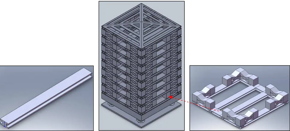
i. Design 1 using IBeam
Figure 2: Front and right view of design 1
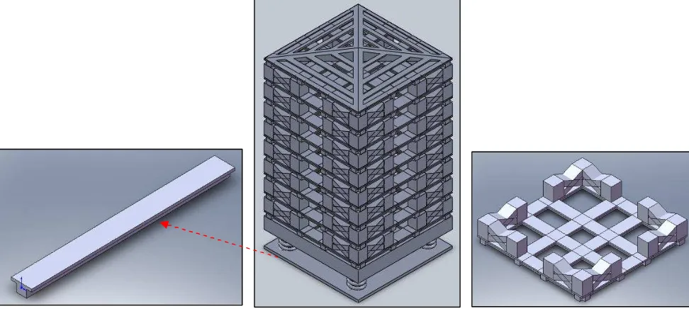
Figure 3: Top and isometric view of design 1 ii. Design 2 using TBeam
Figure 5: Front and right view of design 2
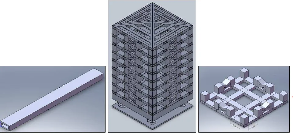
Figure 6: Top and isometric view of design 2 iii. Design 3 using Hollow Beam
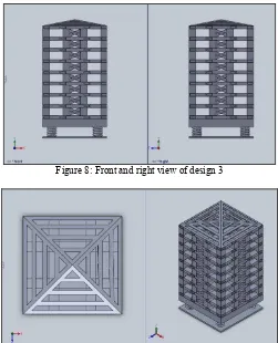
Figure 8: Front and right view of design 3
Figure 9: Top and isometric view of design 3
4. Structural Modeling
i. Normal stress second of moment inertia for beam in bending phenomena with TBeam cross section area.
Figure 10: Cross section area of TBeam Bending moment,
Area,
Then, TBeam is divided into 2 rectangles, and to find centroid value.
Table 1: Calculation of area
C1
C2
5
15
40
Y1= 17.5
Y2= 7.5
20
A1
Area, mm 2 Y
i ,mm Ai Yi ,mm 3
A1 (5) (40) = 200 17.5 3500
A2 (15) (20) = 300 7.5 2250
Total Σ =500 Σ = 5750
Then, second moment of inertia, was calculated,
Figure 11: Rectangle cross section area, for TBeam
By applying parallelaxis theorem,
Then, distance for and is
The second moment of inertia, can be determined using parallelaxis theorem for both rectangles, and , respectively.
Maximum tensile stress is
Maximum compressive stress is
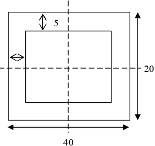
ii. Normal stress and second moment of inertia for beam in bending phenomena with HollowBeam cross section area.
b
Figure 12: Square cross section area, for HollowBeam The HollowBeam in Figure 12 can be divided into two sections and it shows in Figure 13.
iii. iv. v. vi. vii. viii. ix. x. xi.
Figure 13: Section of HollowBeam Material property of these HollowBeam shows in Table 2.
Table 2: Material properties
No Description Value
1 Material Aluminum alloy
2 Yield stress, 275 MPa
3 Ultimate stress, 415 MPa
4 Young Modulus, 73 GPa
5 Safety factor, F.S 3.00
The second moment of inertia is
Allowable stress is
Hence,
Then, the bending moment is
5
20
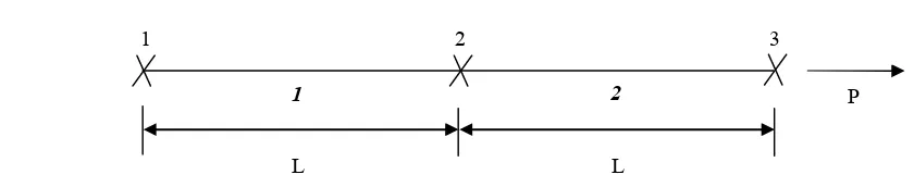
iii. Finite Element Analysis (FEA)
Figure 14: Boundary condition, nodal point of the high rise structural
The dimensional of this structure are: length, , Force, , Young Modulus, , cross section area, The boundary condition, for nodal 1 are , and , respectively. For element 1 and 2, there were shown in equation 1.5 and 1.6 below.
Then, substitute equation (1.11) into (1.12).
On the other hand,
5. Conclusion
The newly improved designed structural building have been made in order to solve the problem occurred in the highrise building during earthquake. The structural designs are being analyzed and the research on the structural building design of highrise building is being made to know the specific problem that related on this structural design. The study about the effect of earthquake on highrise building, building characteristics and also earthquake engineering are done. The conceptual designs are being made to follow the specification and application that involve on the highrise building. From the conceptual design, three selected design have been chosen which the most suitable designs are being illustrated by using the Solid work software. The calculation is done in each design to measure the most suitable design that will be used in further analysis. The analysis on the structural design also being made to determine the most strengthen and deformed shape in the analysis. On the analysis the value of force, shear strain, allowable stress, maximum stress, moments and stress (maximum shear) will be determined. Experiments was conducted on the building structure. The graph of mobility against frequency obtained from the experiment shows that when the mobility is high, the frequency also proportional to the mobility. Mobility equals to Vibration divided by Force (M=V/F). The vibration part of the equation can be in either acceleration or velocity and it is frequency related. It is shows that when the building structure start to mobilize, there are deformation occurred which give the phase data against the frequency. This is happen because when the spring received force from the outside. The spring will react to make sure the building will be in stability. The first reaction from the spring to the building will give high amplitude and then when the building becomes stable, the amplitude is starting to decrease until to its final value. So, the objectives to design the suitable highrise building using numerical approach and to develop an experimental rig on highrise building have been achieved.
6. Acknowledgement
The authors would like to acknowledge Faculty of Mechanical Engineering, Universiti Teknikal Malaysia Melaka for supporting this work through a short term grant.
7. References
[1] Wolfgang Schueller., HighRise Building Structures. Iohn Wiley & Sons, Inc. 1977
[2] Bungale ST. Structural analysis and design of tall building. New York: The William Byrd Press; 1988.
[3] Li GQ, Li QS. Theory and its application of timedependent reliability of engineering structures. Beijing: Science Press; 2001. [4] Li QS, Li ZN, Li GQ, Meng JF, Tang J. Experimental and numerical seismic investigations of the Three Gorges Dam.
Engineering Structures 2005;27: 501_13.
[5] Lv XL, Zou Y, Lu WS. Shaking table model test on Shanghai World Financial Center Tower. Earthquake Engineering & Structural Dynamics 2007; 36: 439_47.
[6] Ou JP, Long X, Li QS, Xiao YQ. Vibration control of steel jacket offshore platform structures with damping isolation systems. Engineering Structures 2007;29: 1525_38.