Fabrication of deep micro-holes in reaction-bonded SiC by ultrasonic
cavitation assisted micro-EDM
Pay Jun Liew
a,c, Jiwang Yan
b,n, Tsunemoto Kuriyagawa
aa
Department of Mechanical Systems and Design, Tohoku University, Aramaki Aoba 6-6-01, Aoba-ku, Sendai 980-8579, Japan bDepartment of Mechanical Engineering, Faculty of Science and Technology, Keio University, Hiyoshi 3
–14-1, Kohoku-ku, Yokohama 223-8522, Japan c
Manufacturing Process Department, Faculty of Manufacturing Engineering, Universiti Teknikal Malaysia Melaka, Hang Tuah Jaya, 76100 Durian Tunggal, Melaka, Malaysia Available online 30 September 2013
Keywords:
Ultrasonic vibration was applied to dielectric fluid by a probe-type vibrator to assist micro electrical discharge machining of deep micro-holes in ceramic materials. Changes of machined hole depth, hole geometry, surface topography, machining stability and tool material deposition under various machining conditions were investigated. Results show that ultrasonic vibration not only induces stirring effect, but also causes cloud cavitation effect which is helpful for removing debris and preventing tool material deposition on machined surface. The machining characteristics are strongly affected by the vibration amplitude, and the best machining performance is obtained when carbon nanofibers are added into the vibrated dielectricfluid. As test pieces, micro-holes having 10μm level diameters and high aspect ratios (420) were successfully fabricated on reaction-bonded silicon carbide in a few minutes. The hybrid EDM process combining ultrasonic cavitation and carbon nanofiber addition is demonstrated to be useful for fabricating microstructures on hard brittle ceramic materials.
&2013 Elsevier Ltd. All rights reserved.
1. Introduction
Electrical discharge machining (EDM) is one of the most popular unconventional machining processes used for producing complex shapes that are difficult to machine using other conven-tional processes. In EDM, a tool and a workpiece are submerged in a dielectricfluid, and the workpiece material is removed by means of repetitive spark discharges from electric pulse generators[1–2].
EDM has many advantages, such as low installation cost and capability to machine complex three-dimensional shapes easily in spite of material hardness [3]. In recent years, micro-EDM is strongly expected to be used for generating three-dimensional microstructures, such as holes, grooves and micro-dimples, on reaction-bonded silicon carbide (RB-SiC).
However, due to the narrow sparking gap in micro-EDM, the removal of debris is remaining a challenging issue, especially in deep hole machining and fine finishing with lower discharge energy. When the debris concentration at the bottom of the gap between the electrode and workpiece reaches a certain critical value, it will not only deform the machined geometry[4], but also lower the surface integrity of the workpiece by forming micro-cracks and thickened heat affected zones[5].
To overcome these problems, several approaches have been attempted by previous researchers, such as orbital electrode actua-tion [6], flushing [7,8], planetary movement of electrode [9], ultrasonic vibration of workpiece [10], dielectric fluid tank [11]
and tool [12]. Ultrasonic vibration has also been carried out in combination with other process improvements, such as EDM using non-circular electrode [13,14], planetary movement of tool [15], helical micro-tool[16], and micro-powders[17]. The use of ultra-sonic cavitation in macro-EDM of carbon fiber reinforced plastic (CFRP) to remove debris also has been attempted [18]. However, whether ultrasonic cavitation is effective or not in micro-EDM has not been clarified yet, especially in micro-EDM of deep micro-holes of ceramic materials.
In this paper, ultrasonic vibration was directly applied to the dielectric fluid in the machining region by using a probe-type vibrator (instead of vibrating the dielectric tank) to generate cavitation to assist micro-EDM of deep micro-holes in RB-SiC. The effect of ultrasonic vibration was investigated in combination with the addition of carbon nanofibers into dielectric fluid. As shown in the previous paper of the present authors [19], by adding carbon nanofibers in the dielectric fluid, the electrical discharge machinability of RB-SiC can be significantly improved. However, there are still problems such as tool material deposition on workpiece surface [20], and the machining efficiency is dis-tinctly lower compared with the EDM of metal materials. In the present study, a hybrid EDM process by combining ultrasonic Contents lists available atScienceDirect
journal homepage:www.elsevier.com/locate/ijmactool
International Journal of Machine Tools & Manufacture
0890-6955/$ - see front matter&2013 Elsevier Ltd. All rights reserved.
http://dx.doi.org/10.1016/j.ijmachtools.2013.09.010 n
Corresponding author. Tel.:þ81 455661445; fax:þ81 455661495.
cavitation and carbon nanofiber addition is proposed to improve machining efficiency, surface quality and form accuracy of deep micro-holes in RB-SiC ceramic material.
2. Experimental
2.1. Method
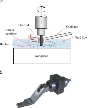
The proposed hybrid micro-EDM method by combining ultra-sonic cavitation and carbon nanofibers addition is schematically shown in Fig. 1(a). A suitable amount of carbon nanofibers are added and mixed in the dielectric fluid and then a probe-type oscillator horn is placed into the dielectricfluid over the workpiece. When ultrasonic vibration is applied to the dielectricfluid, intense ultrasonic waves travel through the liquid, generating small cavities that enlarge and collapse. This phenomenon is called as cavitation
[21]. In conventional EDM, the debris is removed by gaseous bubbles escaping from the working area through the discharge gap[15,22]. In this study, instead of gaseous bubbles, the ultrasonic cavitation will dominate the removal of discharge-induced debris. Thus, stable machining performance might be obtained.
The probe-type vibrator (oscillator horn) used in this study enables concentrative vibration of the dielectricfluid in the machin-ing region, whereas the unmachined regions are less affected. Therefore, very strong ultrasonic cavitation may be generated at very low energy consumption. From this meaning, the vibration mechan-ism in this study is distinctly different from those in traditional ultrasonic vibration which is applied to the dielectric tank.
On the other hand, carbon nanofibers play an important role in the EDM process of low-conductivity RB-SiC material, as shown previously [19,20]. The excellent electrical conductivity of carbon nanofiber can reduce the insulating strength of the dielectricfluid and increase the spark gap distance, leading to a high material removal rate and better surfacefinish. In the hybrid EDM method, the ultrasonic vibration of dielectric fluid causes strong stirring effect which prevents the carbon nanofibers from aggregation, so that the nanofibers disperse uniformly in the dielectric fluid. As a result, frequency of electro discharge in the EDM of RB-SiC might be improved.
2.2. Experimental setup
A micro-EDM machine, Panasonic MG-ED82W, produced by Matsushita Electric Industrial Co., Ltd., was used in this experi-ment. This machine is energized by a resistor-capacitor (RC) type pulse generator. The electrical capacitance is determined by condensers C1–C4, where the capacities are 3300 pF, 220 pF,
100 pF and 10 pF, respectively. This machine is capable of doing micro-wire EDM and micro-die sinking machining, with a step-ping resolution of 0.1mm. To excite vibration of dielectricfluid, a
probe-type ultrasonic cavitation generator (Fig. 1b) SC-450 (Taga Electric Co., Ltd., Japan) [23]with a power output of 50 W was used in this experiment. It has vibration frequency of 20 kHz and maximum amplitude of 14μm. During the EDM process, the tool
electrode was inserted through the hole at the end of the oscillator horn of the cavitation generator. The oscillator horn was placed 2–3 mm from the workpiece. Ultrasonic vibration was applied to
the dielectricfluid directly by the oscillator horn, which causes the cavitation effect.
2.3. Materials
An important ceramic mold material, RB-SiC, was used as workpiece in this study. The RB-SiC material composed of 6H-SiC grains (grain size1μm, 88% in volume) and a Si matrix (12% in
volume). The as-received samples were cylinders with a diameter of 30 mm and a thickness of 10 mm. The electrical resistivity of the sample is 1453Ωcm. The tool electrode used in this experiment was tungsten. Commercially available EDM oil, Casty Lube EDS (Nikko Casty Co., Ltd.) was used as dielectricfluid. High conduc-tivity carbon nanofibers, 150 nm in diameter and 6–8mm in length,
were used as an additive in dielectric.
2.4. Machining conditions
First, effect of vibration amplitude on machining efficiency was investigated. For comparison, two types of micro-EDM tests were carried out, namely, (1) ultrasonic cavitation in pure EDM oil, and (2) ultrasonic cavitation in EDM oil mixed with carbon nanofibers. Micro-hole machining was performed on the sample for duration of specified time, and average of three tests for each parameter setting was taken. Electrode dressing was performed after each EDM cycle by using wire electro discharge grinding (WEDG) in order to improve the form accuracy.Table 1 shows the experi-mental conditions.
Fig. 1.(a) Schematic diagram of the proposed hybrid micro-EDM process and (b) photograph of the probe-type oscillator horn used in the experiment.
Table 1
Condenser capacitance (pF) Stray capacitance, 3300 Vibration frequency (kHz) 2071.5
Vibration amplitude (mm) 0–14
Dielectricfluid EDM oil (CASTY-LUBE EDS) Additive Carbon nanofibers (CNFs) CNFs size (μm) Diameter¼0.15, Length¼6–8
2.5. Measurement and evaluation
In order to examine the microstructure of the samples, surface topography of the machined micro-holes was examined by a scanning electron microscope (SEM), SU1510 (Hitachi, Co., Ltd.). The depth, surface roughness and cross-sectional profile of micro-holes after the EDM tests were measured using a laser probe profilometer NH–3SP (Mitaka Kouki Co. Ltd.). The measurement of
surface roughness was performed across the center of the micro cavity along the radial direction, and the evaluation length was 100μm. Energy dispersive X-ray spectroscopy (EDX) was used to
detect material migration and measure the amount of migrated material. In order to clarify the machining stability, tool electrode
movement in theZ-direction during EDM test was captured using a Keyence high speed camera, and then VW9000 Motion Analyzer software was used to track the movement of the electrode.
3. Results and discussion
3.1. Effect of vibration amplitude
Fig. 2illustrates the effect of vibration amplitude on the depth of machined micro hole, with 0.06 g/L carbon nanofibers concen-tration in the dielectricfluid. The machining time for each test was 2 min. It is seen that the depth of machined hole increases rapidly
70 80 90 100 110 120 130 140
7 9 11 13 15
Hole depth (µm)
Amplitude (µm)
Fig. 2.Effect of vibration amplitude on depth of machined micro-hole.
0 50 100 150 200
30 60 90 120 150
Hole Depth (µm)
Time (s) Cavitation+CNFs
Cavitation
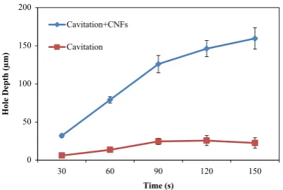
Fig. 3.Change in depth of micro-hole with time when ultrasonic cavitation is used in dielectric oil with/without CNF addition.
Fig. 4.SEM micrographs of micro-holes after machining time of 2 min with ultrasonic cavitation in (a) pure EDM oil and (b) carbon nanofibers mixed EDM oil.
-35 -30 -25 -20 -15 -10 -5 0 5
0 100 200 300 400
Depth (µm)
Distance (µm)
-120 -100 -80 -60 -40 -20 0 20
Depth (µm)
Distance (µm)
0 100 200 300 400
when the amplitude increased from 8mm to 10mm. However,
when the amplitude increases further, the depth of machined hole tends to decrease. At excessively high amplitude, the increase in number of cavitation bubbles might block the dielectricfluid from
flowing into the sparking gap. This phenomenon makes the machining process unstable, leading to the reduction of material removal rate. The results in Fig. 2 indicate that the optimum vibration amplitude for increasing the material removal rate is 10mm.
3.2. Hybrid effect of ultrasonic cavitation and carbon nanofiber addition
Fig. 3shows changes in machined hole depth under conditions (1) ultrasonic cavitation in pure EDM oil, and (2) ultrasonic cavitation in carbon nanofibers mixed EDM oil, respectively. The vibration amplitude in this case is 10mm. Compared to using
ultrasonic cavitation in pure EDM oil, when using ultrasonic cavitation in carbon nanofibers mixed EDM oil the material
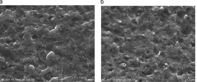
Fig. 6.SEM micrographs of machined surfaces after machining time of 2 min with ultrasonic cavitation in (a) pure EDM oil and (b) carbon nanofibers mixed EDM oil.
-35 -25 -15 -5 5 15
Feed
(µ
m
)
0 2 4 6 8 10 12
Time (s)
-35 -25 -15 -5 5 15
Fe
e
d
(
µ
m)
0 2 4 6 8 10 12
Time (s)
Fig. 7.Measurement results of electrode movement with ultrasonic cavitation in (a) pure EDM oil and (b) carbon nanofibers mixed EDM oil.
Tungsten particles
Tungsten particles
removal rate and the depth of micro hole is increased by 5–7
times. Due to the vibration-induced cavitation bubbles and strong stirring effect, the carbon nanofibers are distributed uniformly in the machining region without aggregation. As a result, the carbon nanofibers can fully play their role in EDM, leading to increases in discharge gap, discharge frequency and material removal rate. From this meaning, there is a kind of synergistic effect between ultrasonic cavitation and carbon nanofiber addition for improving machining performance in the micro-EDM of RB-SiC.
3.3. Micro hole geometry
Next, hole geometry after EDM was investigated.Fig. 4presents SEM micrographs of machined micro-holes obtained with ultra-sonic cavitation in pure EDM oil and carbon nanofibers mixed EDM oil.Fig. 5a and b shows typical cross-sectional profiles of the micro-holes shown inFig. 4a and b, respectively. The profiles were measured by laser probe profilometer NH–3SP. It is clear that with
ultrasonic cavitation in pure EDM oil (Figs. 4a and 5a), a cone shape protrusion was formed in the center of the micro hole. However, when ultrasonic cavitation is used in carbon nanofibers mixed EDM oil, as shown inFigs. 4(b) and5(b), the bottom of the micro-hole becameflat. At the same time, the depth of micro-hole is remarkably deeper inFig. 5(b) compared to the one inFig. 5(a). In pure EDM oil, stagnation of debris occurs easily at the center of micro-cavities where the debris interacts with the tool electrode[4]. This phenomenon causes concavity at the center of tool tip[4,19]. When carbon nanofibers are added into the dielectricfluid, however,
the insulating strength of dielectricfluid will be reduced, and a bigger discharge gap is obtained between the tool electrode and the workpiece[19]. Thus, debris will beflushed out effectively with the help of ultrasonic cavitation bubbles and debris concentration at the center of micro-hole will be prevented. This indicates again that the combination of ultrasonic cavitation and addition of carbon nanofi -bers in the dielectricfluid, rather than using either of them alone, is essential.
3.4. Surface topography
Fig. 6shows SEM micrographs of the machined surface. With ultrasonic cavitation in pure EDM oil, the surface of the micro-hole is very rough (0.28mmRa) and covered with resolidified material
(Fig. 6a). In contrast, in Fig. 6(b), the surface machined with ultrasonic cavitation in carbon nanofiber mixed EDM oil is smoother (0.20mmRa), and surface craters are remarkably smaller.
Different from vibration-assisted EDM of metal materials[24], the material removal mechanism in vibration-assisted EDM of RB-SiC involves spalling of large flakes, leading to a rough surface. However, the spalling of large flakes can be prevented by the hybrid EDM process using ultrasonic cavitation and carbon
nano-fiber addition in the dielectricfluid.
3.5. Stability of machining process
As the EDM machine employs an automatic feed control system, if short circuit occurs because of tool-workpiece contact or adhesion of debris, then the tool electrode is moved in the reverse direction of the feed to maintain the tool-workpiece gap.
0 1 2 3 4 5 6 7 8 9
Without cavitation With cavitation
Tungsten wt (%)
Conditions
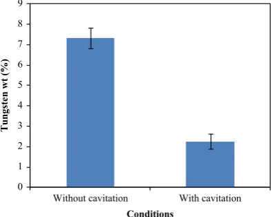
Fig. 9.Weight percentage of deposited electrode material with/without cavitation.
Fig. 10. Micro-holes obtained with (a) 50mm and (b) 23mm diameter tool electrodes.
This back-feeding action indicates the EDM process is unstable and results in the increase of machining time [25]. In this study, in order to investigate the machining stability, we captured and tracked the electrode movement.
Fig. 7 shows the measurement results of electrode movement when ultrasonic cavitation was used in pure EDM oil and carbon nanofibers mixed EDM oil. Frequent back-feeding actions occurred in Fig. 7a, indicating the occurrence of abnormal discharge and unstable machining situation. In Fig. 7b, however, continuous feeding action of electrode toward the workpiece is observed without reverse action. This result demonstrates again that the hybrid process of ultrasonic cavitation and addition of carbon
nanofibers in dielectric fluid improves the process stability and material removal rate.
3.6. Effect of ultrasonic vibration on tool material deposition
Fig. 8 presents SEM micrographs of surface machined at low energy forfine machining (70 V, stray capacitance,) with carbon nanofibers addition in dielectricfluid (concentration 0.06 g/L) with/ without ultrasonic vibration. Without ultrasonic cavitation, many tungsten particles are deposited on the workpiece surface (Fig. 8a). In contrast, with ultrasonic cavitation the tungsten particle deposi-tion is reduced significantly (Fig. 8b).
Fig. 9 shows tungsten weight percentage analyzed by EDX for both conditions. The weight percentage of deposited tungsten decreases by a factor of 3 by using ultrasonic cavitation. With ultrasonic cavitation, the cavitation bubbles oscillate rapidly at the working area, preventing the tungsten debris deposition.
3.7. Fabrication of high aspect ratio micro-hole
Next, we attempted to fabricate high aspect ratio micro-holes using the hybrid effects of ultrasonic cavitation and carbon nanofiber addition in dielectric fluid. Tungsten rods with dia-meters of 50mm and 23mm were used as tool electrodes. SEM
micrographs of the machined micro-holes are shown inFig. 10. An aspect ratio of 11.5 was achieved within 10 min by using the
0.2 0.25 0.3 0.35
0 100 200 300 400 500 600
Surface roughness, Ra (µm)
Depth of micro hole (µm)
Fig. 12.Surface roughness at different depth of micro hole.
Electrode
Workpiece
Small
bubble
Workpiece
Bubble Electrode
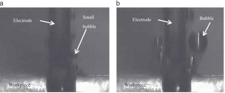
Fig. 13.High speed camera observation of micro-EDM without ultrasonic cavitation: (a) early stage and (b) later stage.
Electrode
Workpiece
Cloud cavitation
Workpiece Electrode
Cloud cavitation
50mm diameter tool, and an aspect ratio of 21.7 was obtained with
the 23mm electrode in 4 min.
In order to examine the inner surface quality of the high aspect ratio micro-hole, the sample inFig. 10(a) was cross-sectioned by a diamond cutter and polished using diamond slurry and observed by SEM.Fig. 11shows an SEM micrograph of the hole cross section. The bottom of the micro-hole isflat without cone shape protru-sion. The surface roughness of hole side walls were then measured using the laser probe profilometer at three locations of different hole depths. As shown in Fig. 12, the surface roughness ranges from 0.24 to 0.32mmRa and does not show obvious change with
the depth of micro-hole. This result indicates that the ultrasonic cavitation is effective even at the deep region of the micro-hole.
4. Process mechanism
To reveal the hybrid micro-EDM process mechanism, we observed the machining tests with/without ultrasonic cavitation using a high speed camera. To ease observation, the RB-SiC workpiece was attached to a plate of glass, and EDM tests were performed along the interface of RB-SiC and glass. High speed camera observation was done from the glass side perpendicularly to the feed direction of the tool electrode. In this way, cavitation bubbles can be clearly seen through the transparent glass. As shown in Fig. 13, without ultrasonic cavitation, lots of small
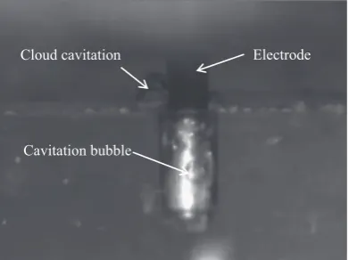
bubbles are createdfirst (Fig. 13a), and then these small bubbles continue to grow in size until theyfinally collapse (Fig. 13b). In contrast, with ultrasonic cavitation, the cavitation bubbles tend to accumulate, forming cloud cavitation (Fig. 14a). These clouds cavitation oscillate around the working area rapidly, helping to remove debris from the sparking gap (Fig. 14b). In deeper region, as shown inFig. 15, cavitation bubbles are also observed. Due to the buoyancy force, these cavitation bubbles rise towards the surface region, which is helpful to carry out the debris from the machining gap.
Cavitation phenomenon is strongly related to acoustic pressure
Pac, as determined in Eq.(1) [26]:
Pac¼2πfusAρc ð1Þ
where fusis oscillations frequency (Hz),ρ dielectric fluid density
(kg/m3), c sound velocity in dielectric (m/s) and A vibration
amplitude (m). According to Ghiculescu et al. [27], to produce cavitation, Pac must be greater than a cavitation threshold. The
cavitation threshold mainly depends on the ambient pressure (1 bar) [28]. In this study, fus¼20 kHz, A¼10mm, ρ¼767 kg/m3
andc¼1320 m/s. Under these conditions, the acoustic pressurePac
is 1.27 MPa. From this result, we can see that the acoustic pressure is far greater than the ambient pressure. In other words, the acoustic pressure is sufficiently high to cause cavitation bubbles in this study.
Normally, in a cavitation process, bubbles grow and collapse. However, in the present study, we found that cloud cavitation oscillating around the machining area instead of collapse. Accord-ing to Suslick [21], cavity growth depends on the intensity of sound. In the case of low intensity ultrasound (20 kHz), the cavity size will not grow and collapse as the one induced by high intensity ultrasound. Instead, these cavities will simply oscillate, often nonlinearly, for many cycles of expansion and compression. A cloud cavitation will be formed when these stable cavities gathered at equilibrium position, i.e., the pressure nodes level
[29]. In a cloud cavitation, the nonlinear bubble dynamics pro-duces nonlinear interactive effects which cause cascading of
fluctuation energy[30,31]. Due to the fluctuating energy in the dielectricfluid, the debris might beflushed out from the gap.
The schematic model for debris removal through the cavitation assisted micro-EDM of a deep micro-hole is shown in Fig. 16. By using ultrasonic vibration, two effects might be expected. One is the vibration-induced stirring effect which is helpful to uni-formly distribute the carbon nanofibers in the dielectricfluid. The other is the vibration-induced cloud cavitation bubbles which help
Electrode Cloud cavitation
Cavitation bubble
Fig. 15.High speed camera observation of deep region when using ultrasonic cavitation.
toflush out the debris. Due to these two effects, short circuit and unstable machining can be prevented, leading to significant improvement in EDM performance. From this meaning, the proposed hybrid micro-EDM method in this study provides possibility for high-efficiency precision manufacturing of micro-structures on ultra-hard RB-SiC ceramic materials.
5. Conclusions
Ultrasonic cavitation assisted micro-EDM of deep holes was proposed and verified by machining tests of RB-SiC. Effects of ultrasonic vibration on hole depth, hole geometry, surface topo-graphy, process stability and tool material deposition were experi-mentally investigated. The main conclusions are summarized as follows:
1. Ultrasonic vibration of dielectric fluid using a probe-type vibrator is effective to improve the micro-EDM performance including material removal rate, maximum machining depth, surface topography, hole geometry, and process stability. 2. The effect of ultrasonic vibration is significant only when
carbon nanofibers are mixed in the dielectric fluid. Without carbon nanofibers, the effect of ultrasonic cavitation alone is insignificant.
3. Vibration amplitude strongly affects the depth of machined micro hole. The maximum depth of micro hole was achieved at vibration amplitude of 10mm.
4. Ultrasonic vibration induces two major effects. One is stirring effect which is helpful to uniformly distribute the carbon nanofibers in the dielectricfluid. The other is the cloud cavita-tion bubbles which help toflush out the debris.
5. Cloud cavitation is generated not only in surface region, but also in deep region. It is the upward flow and oscillation of cavitation bubbles that help to remove the debris.
6. Micro-holes having ten micron level diameters and high aspect ratios (420) were successfully fabricated on reaction-bonded
silicon carbide in a few minutes.
Acknowledgments
The authors would like to thank Taga Denki Co., Ltd., Japan for providing the ultrasonic cavitation equipment. Professor Hitoshi Soyama of Department of Nanomechanics, Tohoku University is gratefully acknowledged for his valuable comments and advices. One of the authors P.J. Liew acknowledges the financial support from Ministry of Higher Education (MoHE) and Universiti Teknikal Malaysia Melaka (UTeM) for her Ph.D. scholarship.
References
[1]O.A. Abu Zeid, On the effect of electrodischarge machining parameters on the fatigue life of AISI D6 tool steel, Journal of Materials Processing Technology 68 (1) (1997) 27–32.
[2]M.P. Jahan, Y.S. Wong, M. Rahman, A study on thefine-finish die-sinking micro-EDM of tungsten carbide using different electrode materials, Journal of Materials Processing Technology 209 (2009) 3956–3967.
[3]D. Reynaerts, W. Meeusen, H.V. Brussel, Machining of three-dimensional microstructures in silicon by electro-discharge machining, Sensors and Actua-tors A 67 (1998) 159–165.
[4]B. Ekmekci, A. Sayar, Debris and consequences in micro electric discharge machining of micro-holes, International Journal of Machine Tools and Man-ufacture 65 (2013) 58–67.
[5]S.H. Yeo, L.K. Tan, Effects of ultrasonic vibrations in micro electro-discharge machining of microholes, Journal of Micromechanics and Microengineering 9 (1999) 345–352.
[6]E. Bamberg, S. Heamawatanachai, Orbital electrode actuation to improve efficiency of drilling micro-holes by micro-EDM, Journal of Materials Proces-sing Technology 209 (2009) 1826–1834.
[7]Y.S. Wong, L.C. Lim, L.C. Lee, Effects offlushing on electro-discharge machined surfaces, Journal of Materials Processing Technology 48 (1995) 299–305. [8]T. Masuzawa, X. Cui, N. Taniguchi, Improved jetflushing for EDM, Annals of the
CIRP 41 (1) (1992) 239–242.
[9]Z.Y. Yu, K.P. Rajurkar, H. Shen, High aspect ratio and complex shaped blind micro-holes by micro-EDM, CIRP Annals–Manufacturing Technology 51 (1) (2002) 359–362.
[10]C. Gao, Z. Liu, A study of ultrasonically aided micro-electrical-discharge machining by the application of workpiece vibration, Journal of Materials Processing Technology 139 (2003) 226–228.
[11]B.H. Yan, M.D. Chen, Effect of ultrasonic vibration on electrical discharge machining characteristics of Ti–6Al–4 V alloy, Journal of Japan Institute of Light Metals 44 (5) (1994) 281–285.
[12]H. Huang, H. Zhang, L. Zhou, H.Y. Zheng, Ultrasonic vibration assisted electro-discharge machining of microholes in nitinol, Journal of Micromechanics and Microengineering 13 (2003) 693–700.
[13]W. Zhao, Z. Wang, S. Di, G. Chi, H. Wei, Ultrasonic and electric discharge machining to deep and small hole on titanium alloy, Journal of Materials Processing Technology 120 (2002) 101–106.
[14]H. Tong, Y. Li, Y. Wang, Experimental research on vibration assisted EDM of micro-structures with non-circular cross-section, Journal of Materials Proces-sing Technology 208 (2008) 289–298.
[15]Z.Y. Yu, Y. Zhang, J. Li, J. Luan, F. Zhao, D. Guo, High aspect ratio micro-hole drilling aided with ultrasonic vibration and planetary movement of electrode by micro-EDM, CIRP Annals–Manufacturing Technology 58 (2009) 213–216.
[16]J.C. Hung, J.K. Lin, B.H. Yan, H.S. Liu, P.H. Ho, Using a helical micro-tool in micro-EDM combined with ultrasonic vibration for micro-hole machining, Journal of Micromechanics and Microengineering 16 (2006) 2705–2713. [17]G.S. Prihandana, M. Mahardika, M. Hamdi, Y.S. Wong, K. Mitsui, Effect of
micro-powder suspension and ultrasonic vibration of dielectricfluid in micro-EDM processes-Taguchi approach, International Journal of Machine Tools and Manufacture 49 (2009) 1035–1041.
[18]H. Ogawa, S. Hamada, T. Aoyama, Ultrasonic cavitation assisted EDM of CFRP, Electrical Machining Technology 36 (112) (2012) 21–26. (in japanese). [19]P.J. Liew, J. Yan, T. Kuriyagawa, Carbon nanofiber assisted micro electro
discharge machining of reaction-bonded silicon carbide, Journal of Materials Processing Technology 213 (7) (2013) 1076–1087.
[20]P.J. Liew, J. Yan, T. Kuriyagawa, Experimental investigation on material migration phenomena in micro-EDM of reaction-bonded silicon carbide, Applied Surface Science 276 (2013) 731–743.
[21]K.S. Suslick, The chemical effects of ultrasound, Scientific American 260 (1989) 80–86.
[22]J. Wang, F. Han, G. Cheng, F. Zhao, Debris and bubble movements during electrical discharge machining, International Journal of Machine Tools and Manufacture 58 (2012) 11–18.
[23]Technical data provided by the manufacturer, available from〈http://www. tagaele.com/industrial/sc450.html〉.
[24]Y.F. Chen, Y.C. Lin, Surface modifications of Al–Zn–Mg alloy using combined EDM with ultrasonic machining and addition of TiC particles into the dielectric, Journal of Materials Processing Technology 209 (2009) 4343–4350. [25]T. Endo, T. Tsujimoto, K. Mitsui, Study of vibration-assisted micro-EDM-The effect of vibration on machining time and stability of discharge, Precision Engineering 32 (2008) 269–277.
[26]D. Ghiculescu, N.I. Marinescu, G. Jitianu, G. Seritan, On precision improvement by ultrasonics-aided electrodischarge machining, Estonian Journal of Engi-neering 15 (1) (2009) 24–33.
[27]D. Ghiculescu, N.I. Marinescu, S. Nanu, Influence of macro and microgeometry machined surface on ultrasonic aided electrodischarge machining, Interna-tional Journal of Material Forming 1 (2008) 1339–1342.
[28]J.E. Barger, Thresholds of acoustic cavitation in water, Technical Memorandum 57 (1964) 1–174.
[29]J.L. Laborde, C. Bouyer, J.P. Caltagirone, A. Gerard, Acoustic bubble cavitation at low frequencies, Ultrasonics 36 (1998) 589–594.
[30]S. Kumar, C.E. Brennen, Nonlinear effects in the dynamics of clouds of bubbles, Journal of the Acoustical Society of America 89 (1991) 707–714.