UNIVERSITI TEKNIKAL MALAYSIA MELAKA
SURFACE ROUGHNESS MEASUREMENT BY USING IMAGE PROCESSING BASED TECHNIQUES
This report submitted in accordance with requirement of the UniversitiTeknikal Malaysia Melaka (UTeM) for Bachelor Degree of Manufacturing Engineering
(Robotic and Automation) (Hons)
By
WAN FARHAN BIN WAN JUSOH B051110185
8907020-03-5425 EN. RUZAIDI BIN ZAMRI
UNIVERSITI TEKNIKAL MALAYSIA MELAKA
BORANG PENGESAHAN STATUS LAPORAN PROJEK SARJANA MUDA
TAJUK: SURFACE ROUGHNESS MEASUREMENT BY USING IMAGE PROCESSING BASED TECHNIQUES
SESI PENGAJIAN: 2014/2015
Saya WAN FARHAN BIN WAN JUSOH
mengaku membenarkan Laporan PSM ini disimpan di Perpustakaan Universiti Teknikal Malaysia Melaka (UTeM) dengan syarat-syarat kegunaan seperti berikut:
1. Laporan PSM adalah hak milik Universiti Teknikal Malaysia Melaka dan penulis. 2. Perpustakaan Universiti Teknikal Malaysia Melaka dibenarkan membuat salinan
untuk tujuan pengajian sahaja dengan izin penulis.
3. Perpustakaan dibenarkan membuat salinan laporan PSM ini sebagai bahan pertukaran antara institusi pengajian tinggi. atau kepentingan Malaysia sebagaimana yang termaktub dalam AKTA RAHSIA RASMI 1972)
(Mengandungi maklumat TERHAD yang telah ditentukan oleh organisasi/badan di mana penyelidikan dijalankan)
Alamat Tetap:
DECLARATION
I hereby, declared this report entitled “surface roughness measurement by using image processing based techniques” is the results of my own research except as cited in references. the report has been not accepted for any degree and is not concurrently submitted in candidature of any other degree.
Signature : ……….
Author’s Name : ……….
APPROVAL
This report is submitted to the Faculty of Manufacturing Engineering of UTeM as a partial fulfillment of the requirements for the degree of Bachelor of Manufacturing Engineering (Robotics & Automation) (Hons.). The member of the supervisory is as follow:
(Signature of Supervisor)
ABSTRAK
ABSTRACT
DEDICATION
ACKNOWLEDGEMENTS
Bismillahirrahmanirrahim.
Table of Contents
2.2 Surface roughness measurement 4
2.3 Computer vision 5
2.6.1 Journal extraction 10
2.7 Conclusion 10
3 Chapter 3 11
3.1 Introduction 11
3.2 Gantt chart 11
3.3 Flow chart 12
3.5 Literature review 13 3.6 Define the problem statement, objective and scopes 13
3.7 Methodology 13
3.8 System structure 16
3.8.1 Hardware component vision system 16
3.8.2 Mitutoyo surface measument 16
3.8.3 Vision 17
4.4 Image Processing Methods 23
4.4.1 Image acquisition tool 23
4.4.2 Result image 24
4.4.3 Graphical User Interface ( GUI ) 25
4.4.4 Mean gray level value (Ga) 27
4.5 Stylus profile method 27
4.5.1 Average surface roughness (Ra) 28
4.6 Data plotting and regression 28
4.7 Calculate surface roughness (Ra) 29
4.8 Percentage of errors 31
4.9 Root mean square error 32
4.10 Conclusion 33
5 CHAPTER 5 34
5.1 Conclusion 34
5.2 Suggestion for future work 35
References 36
List of figures
Figure 3.1: Flow chart 12
Figure 3.2 : Hardware components vision system 14
Figure 3.3 : Flow chart for experiment 15
Figure 4.1: The optical chart provided by the F500 Vision Setup Manual 21 Figure 4.2: The specimen used in experiment 22 Figure 4.3: Area being captured using high resolution camera. 23 Figure 4.4: Image acquisition tool in Matlab 24
Figure 4.5: Clear image 25
Figure 4.6: Blur image 25
Figure 4.7: Graphical User Interface ( GUI.) 26
List of tables
Table 2.1:List of journals 8
Table 4.1Differences of picture quality due to lighting factor 25 Table 4.2: Mean gray level value for 20 specimens 27 Table 4.3: average surface rouhgness (Ra) 28
Table 4.4: Result for calculate Ra 30
1
Chapter 1
Introduction
Background of Study
Surface roughness have three elements must be identified in accordance with the wavelength or frequency. For low, medium and high frequency variations of different square sizes are referred to as type, waviness and roughness separately. Any surface continues to have three of these components together and to analyze these components need one by one (Mooneghi, Saharkhiz, & Varkiani, 2014). In addition, the surface roughness should consider the determinants of work satisfaction of machined parts (Jeyapoovan & Murugan, 2013).
of the machined components (Jeyapoovan & Murugan, 2013). Workpiece surface finish quality is a key issue on the manufacturing industry and the workpiece surface roughness inspection is a very important technology. Basically, the measurement of surface roughness can be divided into two approaches,methods of direct and indirect (B. Y. Lee & Tarng, 2001). For the direct contact a traditional method to measure the surface roughness based on the stylus profiles, this method using contact nature and give defect of scratching to work pieces, this method also unfit for online application for the slow speed. For the indirect method uses optical instruments which are inherently non- contact measurements and easy to automate (B. Y. Lee & Tarng, 2001). Over the years, a number of texture feature extraction strategies are developed, each of them getting data in a way that is very different. for example, the classic strategy, such as co-occurrence matrix, Gabor filters or approach supported wavelet transform. Recently, several alternative approaches developed to inspect the relationship between pixels in a pattern texture, such an approach supports advanced network theory, the trajectory made by walkers completed, and analysis form (de Mesquita Sá Junior & Ricardo Backes, 2012).
The parameters are the most important characterise to measurement surface roughness is Average Roughness (Ra). Parameter for surface texture is Average Roughness (Ra). Ra is calculated by an algorithm that measures the average length between the peaks and valleys and the deviation from the mean line on the entire surface within the sampling length. The geometrically it can be represented as the total ruled area divided by evaluation length L.
1.1 Problem statement.
In today manufacturing, surface roughness is the important factor to the surface finish. Lots of method can be used to measure the roughness. Direct contact method make use of physical contact between workpiece and measuring apparatus but this method consume a lot of time. This project focus on indirect method to measure the surface roughness using vision system
1.2 Objectives of Study
I. To develop MATLAB code to calculate mean gray level value for images. II. To predict the surface roughness of metallic surface using linear regression.
1.3 Scope of Study
2
Chapter 2
LITERATURE RIVIEW
2.1 Introduction
Chapter two discusses previous studies in the field of machinery that involve surface roughness on the work piece and the techniques have been applied to measure. The detail review of the method of measurement the surface roughness will be shown in this chapter about the information from different kind of sources such as the reference book, journal, internet, etc. will be used. The information also used to design the methodology section, in this section will focus on machine vision system use for measuring the surface roughness.
2.2 Surface roughness measurement
2.3 Computer vision
Computer vision technology has maintained tremendous vitality during a ton of fields. New applications still be found and existing applications to expand. Many investigations are performed to examine surface roughness of a piece of work supported pc vision technology. Though it's been shown that the surface roughness of a workpiece is strongly characterised by the surface image,sensible surface roughness instruments supported computer vision technology are still tough (B. Y. Lee & Tarng, 2001).
2.4 Contact method
For these methods, to make the measurement process, the sensor comes in contact with the surface and calculate the parameters.
2.4.1 Stylus technique
2.5 Non-contact method
There are many techniques to measure the surface roughness in non-contact ways. There is no contact between the sensor and surface with any of these methods.
2.5.1 Light scattering
A light beam of a certain wavelength is created incident on the surface under test at a controllableangle of incidence. once the surface is ideally swish, the incident light-weight is reflected in thesecular direction, specified the angle of incidence equals the angle of reflection. once the surface is rough, a locality or all of the incident beam are scattered away from the reflective region, providing a diffuse beam ( Manoj& Shivakumar, 2010). Light scattering has been used of finding the surface characterization of machined surfaces.used plane polarized light and a scatter light detector for surface characterization. Have a the two methods the angular-resolved scatter (ARS) and total integrated scatter (TIS), the two methods based on light scattering to measure surface roughness. In ARS method, the theoretical expression of ARS against surface roughness involves the state of polarization of the incident light. In TIS method, the light that scatters into a hemisphere from the surface being investigated is collected and measured using a scatter light detector for surface roughness measurement(Jeyapoovan & Murugan, 2013). When the surface is rough, a part or all of the incident beam will be scattered away from the specular region, providing a diffuse beam.
2.5.2 Laser speckle image
Some optical maser speckle techniques were developed to guage the surface roughness.. light-weight scattering caused by surface roughness and then forth specklepictures obtained is also accustomed live the surface roughness(Jeyapoovan & Murugan, 2013). Developed to evaluate the surface roughness.. Light scattering caused by surface roughness and so forth speckle images obtained may be used to measure the surface roughness(Jeyapoovan & Murugan, 2013).
2.5.3 Machine vision
The illumination playsa very importantrolewithin themachine vision system for capturingimage. evaluated the influence of lightingsupply,likegrazing angle and distance betweenlightand specimen, on optical surfaceendparameters extracted fromimage (Z. Zhang, Chen, Shi, Ma, & Jia, 2009). in several manufacturing, Machine vision has been very successfully employed to apply including to material handling, assembly and inspection ( Manoj& Shivakumar, 2010). Machine vision-based techniques area unit appropriate for on-line examination of surfaces of machined components and area unit safe on surfaces being measured and therefore the measuring instrument. Used a vision system to get surface pictures and quantified the surface roughnessemploying a multivariate analysis. the common grey value (Ga) of the surface image was calculated and calibrated with the various average surface roughness (Ra) of the surface measured by the stylus. Used the Gray Level Co-occurrence Matrix (GLCM) method.This method considers the spacial relationship of pixels on the surface image. Surface roughness is extracted by exploring the relationships of average surface roughness (Ra) with the options of GLCM of the surface image (Jeyapoovan & Murugan, 2013).
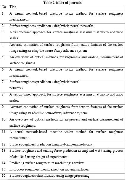
2.6 Journal mapping
have made. The journal mapping develops to guidance in this project. The table 2.1 show the list of journal has be used in this researah.
Refer appendix A table for journal summary
Table 2.1:List of journals No Title
1 A neural network-based machine vision method for surface roughness measurement.
2 Surface roughness prediction using hybrid neural networks.
3 A vision-based approach for surface roughness assessment at micro and nano scales.
4 Accurate estimation of surface roughness from texture features of the surface image using an adaptive neuro-fuzzy inference system.
5 An overview of optical methods for in-process and on-line measurement of surface roughness.
6 A neural network-based machine vision method for surface roughness measurement.
7 Surface roughness prediction using hybrid neural networks.
8 A vision-based approach for surface roughness assessment at micro and nano scales.
9 Accurate estimation of surface roughness from texture features of the surface image using an adaptive neuro-fuzzy inference system.
10 An overview of optical methods for in-process and on-line measurement of surface roughness.
11 A neural network-based machine vision method for surface roughness measurement.
12 Surface roughness prediction using hybrid neuralnetworks.
13 Surface roughness and cutting force prediction in mql and wet turning process of aisi 1045 using design of experiments.
17 3d laserimaging for surface roughness analysis.
18 Optimization of radial basis function neural network employed for prediction of surface roughness in hard turning process using taguchi’s orthogonal arrays. 19 Measurement of rollover in double-sided shearing using image processing and
influence of clearance.
20 Detection of tool condition from the turned surface images using an accurate grey level co-occurrence technique.
21 Surface roughness classification using image processing. 22 Study on prediction of surface quality in machining process.
23 Machine vision based surface roughness measurement with evolvable hardware filter
24 In situ non-contact measurements of surface roughness. 25 Modeling surface roughness in the stone polishing process. 26 Evaluation of surface roughness using
machine vision.
27 The influence of afm and vsi techniques on the accurate calculation of tribological surface roughness parameters a. spencer a,n, i.dobryden b, n.almqvist b, a.almqvist a, r.larsson a
28 A hybrid inspection method for surface defect classification.
29 Determination of seal coat deterioration using image processing methods. 30 Evalution of 3d surface roughness parameter of emd component using vision
system
31 Surface roughness classification using image processing. 32 A simplified gravitational mode to analyze texture roughness. 33 Analysis of surface roughness parameters digital image identification 34 Improved spatial gray level dependence
matrices for texture analysis.
35 Roughness measurement using optical profiler with self-reference laser and stylus instrument- a comparative study.
36 Using artificial neural networks for modeling surface roughness of wood in machining process
38 Application of digital image magnification for surface roughness evaluation using machine vision.
39 A simplified gravitational mode to analyze texture roughness.
40 Analysis of surface roughness parameters digital image identification
2.6.1 Journal extraction
From the journal mapping, an extra one more time to make the graph based on information from mapping. The Graph has been Developed by parameters and method, to make comparison between method in past research.
Refer Appendix A:
2.7 Conclusion
3
Chapter 3
METHODOLOGY
3.1 Introduction
This chapter presents the methodology where it can be described as technique and procedures that will be used in the project in a detailed way. This chapter is designed according to the previous chapter that is literature review and limitation are being considered too. The fifth step has several phases where its phase introduces the various method and tools used in order to reach objectives.
3.2 Gantt chart
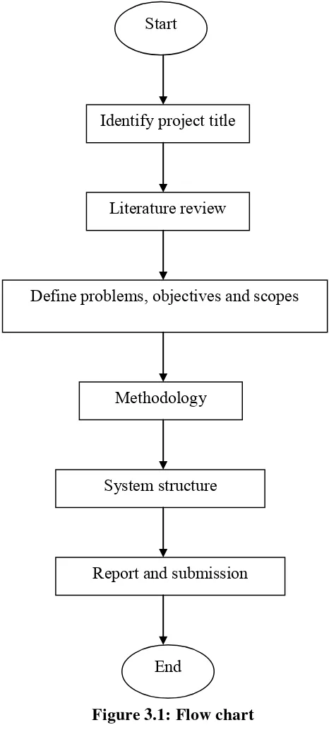
3.3 Flow chart
The figure 3.1 shows the flow chart for this project. Every step explains about the flow of this project starting from title to the submission of full report.
Identify project title Start
Literature review
Report and submission
Define problems, objectives and scopes
Methodology
System structure
End