Stitch Bonding Strength of Cu Wire on AuAg/Pd/Ni Preplated
Cu Leadframes: Influence of AuAg Thickness
Sock Chien Tey
1,a, Kok-Tee Lau
2,b, Mohd Hafizul Mohamad Noor
1,
Yon Loong Tham
1and Mohd Edeerozey Abd Manaf
21Infineon Technologies (Advanced Logic) Sdn. Bhd., Malaysia
2Carbon Research Technolgy Group, Faculty of Manufacturing Engineering,
Universiti Teknikal Malaysia Melaka, Hang Tuah Jaya, 76100, Durian Tunggal, Melaka, Malaysia
a[email protected], b[email protected]
Keywords: Cu diffusion, Thermosonic bonding, Thermocompression, Slip dislocations, Grain boundary.
Abstract. Copper (Cu) wire bonding on the pre-plated leadframes with Ni/Pd/AuAg plating has been applied extensively in the semiconductor industry for the interconnection of integrated-circuit (IC) packaging due to the lower material cost of Cu and its excellent electrical properties. Furthermore, the Cu wire bonding on the preplated leadframe has advantages, such as the tin whisker prevention and the robust package for automotive application. Nevertheless, a stitch bondability of Cu wire-preplated leadframe is facing several challenges, such as the Cu oxidation, the high hardness of Cu wire and the very thin AuAg plating on the leadframes. This paper discusses the effect of AuAg plating thickness in roughened pre-plated leadframe on the stitch bonding of Cu wires with the leadframe. The stitch bonding integrity was assessed using Dage 4000 shear/pull tool at a key wire bond responses of stitch pull at time zero (T0). Results show that the
stitch pull strength of the Cu-leadframe stitch bonding increases with the increase thickness of AuAg layer. FESEM images of the stitch bonding between the Cu wires and the pre-plated leadframes of different AuAg plating thickness did not show any defect in microstructures, thus it suggests that the bonding property is determined by diffusion mechanism at the Cu wire/AuAg stitch bonding interface. Finally, a brief discussion is provided on the stitch bondability of high performance Au-flashed palladium-coated copper wires on the pre-plated leadframe with different AuAg thickness.
Introduction
Copper (Cu) wire bonding on the pre-plated Cu leadframes is used in the current IC packaging industry as it is cheaper than gold (Au) [1]. Cu wires are susceptible to oxidation and have a higher hardness than the Au wires, thus the former wires require a stronger bonding force and ultrasonic energy during bonding [2]. Furthermore, the copper wire bonding to the preplated leadframes was reported to have a lower stitch bond yield than that of the gold wire bonding [3]. A continuous quality improvement of the IC packaging leads to the usage of roughened Ni/Pd/AuAg pre-plated Cu leadframes (manufactured by Samsung Techwin) because it provides whisker-free and reliable bonding as well as mold interlocking function of robust package, particularly for the automotive application. However, the rough and thin plating structure of Ni/Pd/AuAg provides additional bondability challenges during thermosonic bonding process due to the uneven contact surface of the roughened leadframe with the Cu wire surface and the disparity in the thermal and mechanical properties of materials constituting the multilayer plating. The study of Cu wires bonding on the roughened preplated leadframe may provide insight on surface microstructural effect of roughened preplated leadframe on the Cu wires-leadframe bondability, so that it will benefit the future development of high performance leadframe for IC interconnection packaging application.
This paper reports stitch pull strength measurement of Cu wires onto roughened Ni/Pd/AuAg pre-plated Cu leadframes plated with various AuAg thickness. Bonding interface of the stitch
bonding was observed using FESEM to detect possible microstructural defect in bonding microstructure resulted by the different plating thickness.
Experimental
The stitch bonding of Cu wires (5N bare Cu, purity: 99.999 wt%, Tatsuta Electronic Materials Co.) was performed on the roughened Ni/Pd/AuAg pre-plated Cu leadframes (Quad Flat Package [QFP] design, total lead count = 128, Samsung Techwin Co.) with various AuAg thickness, i.e., 9, 15, 24, 31 and 36 nm. The roughened prep-lated leadframes have AuAg layer on the top surface, followed by Pd layer (thickness= 5-10 nm) and Ni layer (thickness= 250-600 nm) on the Cu leadframe. The stitch bonding of Cu wires on the Cu leadframe was performed using the Shinkawa UTC1000 wire bonder (KNS capillary type with Cupra Plus version) at room temperature and in 95 vol% N2-5 vol% H2 gas environment (flowing rate of 0.3-0.5 L/min). The copper wires used in this
study have a diameter of 30 µm.
The stitch bonding quality of Cu-leadframe was assessed using the Dage 4000 pull / shear tool, in which a stitch pull strength of 30 stitch bonds that were randomly picked from five units of the leadframes was measured. The result was further analyzed using Cornerstone software. Using a field-emission scanning electron microscopy (FESEM, Model: SU8020, Hitachi), the surface and cross sections of the stitch bonding were examined to identify any abnormality in the bond microstructure.
Results and Discussion
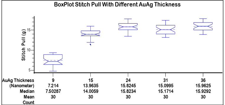
The result of the stitch bond strength is shown in Fig.1. The result shows that the stitch pull strength increases with the increase of AuAg thickness, but then it becomes constant above AuAg thickness of 24 nm. All the bonding samples showed similar failure mode of breaking at the stitch heel, which was acceptable in the wire bonding process.
The high stitch bonding strength of Cu wires at a higher AuAg thickness is probably attributed to a high diffusion activity in the Cu wire/leadframe interface. It is thought that Cu diffused into AuAg because of the smaller Cu atom size than AuAg. No intermetallic compound formation is expected because Cu is completely soluble with AuAg [4]. It is suggested that Cu atom diffused through grain boundaries and active slip planes of AuAg layer as reported elsewhere [5]. AuAg layer’s slip mechanism may be induced by a thermosonic energy or compression supplied by the Cu wire bonder, which increases slip dislocation of AuAg. Thus, it enhances the mobility of Cu atoms [6,7]. In the case of ta hinner AuAg layer, it is expected that less Cu atoms diffused into the slip plane, causing a weaker stitch bonding.
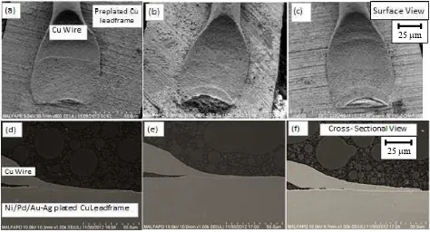
bond (no peeling and clear imprint of tool mark). The cross-sectional views show no thinning and stretch-on-the-heel of the stitch bonds for all bonding samples.
Fig. 2 Surface and cross-sectional FESEM micrographs of stitch bonding of Cu wire on the preplated leadframes with AuAg thickness of: 0.015µm [(a) and (d)], 0.024 µm [(b) and (e)], and 0.036µm [(c) and (d)].
Fig. 3 shows a higher magnification of the bonding interfaces of the Cu wire/leadframes, where the Pd/AuAg and Ni layers were observed to be located below the bonding interface. However, distinct layers of palladium (Pd) and AuAg were not visible due to the FESEM image resolution limit. Studies by Tan et al. and Loh et al. show the layer thinning of Au and sinking on the preplated leadframe surface with Cu wires with different bonding parameters [8,9]. However this was not observed across the bonding surface during the studies. This may due to the different scrubbing mode and parameter during bonding which does not induce the mechanical mixing between the wires and leadframe plating surface [10].
Fig. 3 Cross-sectional FESEM micrographs of bonding interface between Cu wire and preplated leadframes having AuAg thickness of: (a) 15 nm and (b) 36 nm.
In order to improve the stitch bondability, Pd-coated Cu wire treated with Au flash has been developed to protect Cu wire from oxidation and increases the wire’s strain rate. This process in turn improves the bonding strength and provides a bigger window for bonding process [11]. It is
2 µm
25 µm
also believed that the new Pd-coated Cu wire may contribute to a higher stitch pull strength and eliminate the occurrence of non-stick-on-lead failure. Nevertheless, Pd layer on the Cu wire may inhibit diffusion of Cu atoms from Cu wire into AuAg layer, which is observed by Liu et al. where Pd is present between the interface of Cu wire and Ag layers and no Ag was found in the Cu wire [12]. With the addition of Au flash onto the Pd-coated Cu wire, the chemical similarity with the AuAg of pre-plated leadframe and softening effect of the Au flash on the Pt-coated Cu may negate the detrimental effect of the Pd layer as the diffusion barrier of Cu atoms into the AuAg layer in pre-plated leadframe.
Conclusion
Stitch bonding strength of Cu wires on the roughened Ni/Pd/AuAg pre-plated Cu leadframes is affected by the AuAg thickness of the latter. A minimum AuAg thickness of 15 nm is required to achieve sufficient stitch pull strength between the Cu wires and the preplated leadframes. The improved stitch bondability for the leadframes with a thicker AuAg layers is attributed to a higher Cu diffusion level of Cu atoms into the AuAg layer. It is believed that the thicker AuAg layers contain a larger amount of slip dislocations created by the thermosonic or thermocompression energy of the wire bonder, thus increases the rate of Cu diffusion into the AuAg layer. This, in turn increases the stitch bonding strength of the Cu wire on the pre-plated leadframe. Although Pd layer on Pd-coated Cu wires may act as a diffusion barrier for the Cu diffusion into the AuAg layer of pre-plated leadframe, it is predicted that the addition of Au flash onto the Pd-coated Cu wires may negate the detrimental effect of the Pd layer.
Acknowledgements
The authors would like to thank Jolene Tan, Norisham, Ananth, Lim Kee Guan and the wire bond team, Infineon Technologies for the support for this paper. Kok-Tee Lau is gratefully acknowledges Ministry of Education Malaysia for the financial support (Grant No. FRGS(RACE)/2012/FKP/SG07/03/1 F00154).
References:
[1] L.Y. Hung, D.S. Jiang, C.M. Huang, Y.P. Wang, “Investigation of Ultrasonic Pd Coated Cu Wire Wedge Bonding on Different Surface Finish”, Electronics Packaging Technology Conference, pp.705-709, Dec 2011.
[2] C.C. Lee, L.M. Higgins, “Challenges of Cu Wire Bonding and Low-k/ Cu Wafers with BOA Structures”, Electronic Components and Technology Conference, pp.342-349, Jun 2010.
[3] B. An, L. Ding, T.C. Wang, T.L. Lu, L.Q. Sun, Y.P. Wu, “Improvement of the Second Bond Strength in Copper Wire Bonding on Pre-Plated Leadframe”, International Conference on Electronic Packaging Technology and High Density Packaging, pp.391-394, Aug 2011.
[4] X.J. Liu, T.C. Wang, Y.Q. Cong, J.J. Wang, “TEM Study on the Cu Wire Stitch Bonding Interface”, Conference on Electronic Packaging Technology and High Density Packaging, pp.1-5, Aug 2011.
[5] G.G. Harman, Wire Bonding in Microelectronics, third ed., McGraw Hill, New York, 2010. [6] B. Langenecker, Effects of ultrasound on deformation characteristics of metals, IEEE Trans. Sonics Ultrasonics, 13 (1966) 1-8.
[7] L. Levine, “The Ultrasonic Wedge Bonding Mechanism: Two Theories Converge”, Symposium on Microelectronics, ISHM Press, pp.128-131, 1995.
[9] L.J. Loh, K.H. Loh, W.C. Ng, “Further Characterization of Stitch Bond in Bare Cu Wire and Pd Coated Cu Wire on Various Leadframe Plating Scheme”, International Electronic Manufacturing Technology Conference, pp.1-6, Nov 2012.
[10] Y.H. Tian, C.Q. Wang, Y.N. Zhou, Bonding mechanism of ultrasonic wedge bonding of copper wire on Au/Ni/Cu substrate, Trans. Nonferrous Met. Soc. China, 18 (2008) 132-137.
[11] U. Tomohiro, Enhancing bondability with coated copper bonding wires, Microelectron. Reliab. 51 (2011) 88-96.