Design and Analysis of Self-tuned Nonlinear PID Controller for XY Table Ballscrew
Drive System
L. Abdullah, Z. Jamaludin, J. Jamaludin, M.R. Salleh, B. Abu Bakar, M.N. Maslan, T.H Chiew and N.A. Rafan
Centre of Excellence, Advanced Manufacturing Centre, Faculty of Manufacturing Engineering,Universiti Teknikal Malaysia Melaka (UTeM), Hang Tuah Jaya, 76100 Durian Tunggal, Melaka, Malaysia. [email protected], [email protected].
Abstract— Positioning systems in machine tools lately insists
for high accuracy and self adjusting mechanism to be implemented into the system in order to sustain against various disturbance forces. The disturbance forces are in the form of both cutting forces and friction forces. The aim of this paper is to propose a controller namely Nonlinear Proportional Integral Derivative (NPID) to control the position of the system. The tracking error will be compensated by the NPID controller. The tracking performance of NPID controller is compared with conventional PID controller. The degree of robustness of both controllers is quantified based on reduction in the amplitudes of cutting force harmonics using Fast Fourier Transform. It is obvious that the average tracking performance result of NPID controller outweigh the PID controller about 8 % to 40 % better. The finalize design of NPID controller do provide brighter prospect for machining application such as milling process. The execution of NPID controller will offer flexibility since the controller are an adaptive type of controller in which it can automatically adjust for better value of gain based on the error generated from the system. Finally, it is recommended that in order to improvise further the NPID controller, control designer could embedded any type of add on features like dead zone compensator and tracking differentiator into the controller to improve the tracking performance.
Keywords-npid controller; motion control; adaptive control; machine tool;xy table
I. INTRODUCTION
In machine tools application, there are several controllers have been used for the purpose of controlling the position of the system namely PID controller, Cascade Controller [1], Sliding Mode Controller [2] and Fuzzy Logic controller [3,4] to name a few. The conventional PID controller offers a direct approach to obtain preferred result. Nevertheless, as the controller facing different types of disturbance from different type of disturbance source, PID controller tend to face difficulties to control the position and to provide good transient performance [5]. This is due to the fix value of proportional gain, Kp, Integral gain, Ki, and Derivative gain, Kd . Theoretically, those gain values need to be varies when the disturbance values are varied. Then, the idea of gain scheduling controller [6] come in to solve those issue but it involves a messy and tiring job. It is because it requires the control designer to manually tuned those gain values accordingly. A more sophisticated approach like Sliding
Mode Control, Fuzzy logic control and other type of adaptive control are able to rectify the problem of a system with varying load disturbance. Unfortunately, those modern controllers are not preferred in real industrial application due to the complexity and practicality issues. As a result, PID controller is still relevant and a preferred choice in industry thanks to its functional simplicity, cost affordability and easiness to operate. In this paper, the PID controller that intact with self tuned nonlinear gain (known as NPID) is proposed and tested to control the position and tracking of XY table ballscrew drive system. The self tuned nonlinear gain is used to compensate the nonlinearity as well as to rectify the shortage in conventional PID controller. This control strategy is considered because of its simple formulation yet it is efficient to fulfill the job that is incapable to be obtained by linear traditional PID controller.
II. DESIGN OF NONLINEAR PID (NPID) CONTROLLER Self-tuned Nonlinear PID (NPID) controller is chosen to control the position of the system. The system identification process has been done in [7]. Basically, the plant is an XY table ballscrew drive system. The transfer function of the plant is as follows:
3
where Y is the position of the table in millimeter and U is the input voltage signal in volt. The design stages of NPID controller can be divided into 3 parts. The steps namely are :A. Overview on NPID equations and formulae
In general the suggested nonlinear PID (NPID) controller is developed by a sector bounded nonlinear gain, K(e) that is integrated in series (cascade) with PID controller. Fig. 1 illustrates the block diagram of the NPID control system. The parameters of the traditional PID controller are acquired based on previous work [1] which is based on the desired gain and phase margin. The self tuned gain adjustment, K(e) behave as a nonlinear function of error, e(t) which is bounded in the sector 0 ≤ K(e) ≤ K(emax) as pointed out in (2)
2nd International Symposium on Computer, Communication, Control and Automation (3CA 2013)
and (3). These can be classified as the range of available choice for the nonlinear gain, K(e). The output formed from this nonlinear function is acknowledged as scaled error, fe and the equation of fe is presented in (4). Alternatively, the overall equation of NPID controller can be viewed as in (5).
Figure 1. Block diagram of the NPID controlled system [5].
Nonlinear Gain, K(e) =
2
)
exp(
)
exp(
α
e
+
−
α
e
(2)
e ; if |e| ≤ emax
Error, e = emax*sign(e); else |e| > emax
K(emax) =
|
)
(
|
1
ω
j
G
−
(3)Scaled Error, fe = K(e)* e(t) (4) General transfer function of NPID controller,
GNPID(s) = [Kp*fe]+[Ki/s * fe]+ [KdS *fe] (5) B. Guidelines to obtain parameters of NPID controller
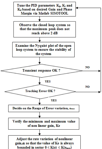
In order to design the NPID controller, the parameters of the PID controller were required to be determined first. Then, it follows with the determination of rate variation of nonlinear gain, α and finally the value of range of variation error, emax. The systematic guidelines to acquire the parameters of NPID controller is illustrated in Fig. 2 as follows :
Figure 2 Step by step procedure to acquire parameters of NPID controller
C. Stability test
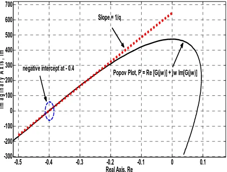
Based on (2), α signify the rate of variation of nonlinear gain whereas emax is the range of error variation. Both value of α and emax are decided to be 0.5 and 3 respectively. The selection of parameters α and emax are opted based on the highest allowable value of nonlinear gain, K(e) which is selected based on the range for stability. Noted that in the case of fix value of PID controller, the Nyquist plot could be utilized for stability test. However, for the case of NPID controller where the value of scaled error, fe keep on changing, the Nyquist plot is no longer valid. Therefore, Popov stability criterion or Lyapunov stability criterion could be employed for the said purpose. For this case, Popov Stability criterion method is utilized to verify the stability as shown in Fig. 3. Popov stability criterion also is used to decide the value of K(e). The procedures to determine the range of K(e) by using Popov stability criterion has been elaborated in great details in previous research [8]. By manipulating the Matlab software, the Popov plot of G(jw) is probably intercept the negative real axis at the point (-0.4, j0) as shown in Fig. 3. Based on this information, the maximum value of the nonlinear gain, K(emax) can be retrieved via (3). As a result, the range of allowable nonlinear gain, K(e) is equivalent to (0, 2.5).
Finally, in theory, a system is absolute stable if the Popov plot, P lies to the right of the intercept line at negative real axis. Hence, the system is stable since it satisfy the said condition.
III. PREPARE YOUR PAPER BEFORE STYLING
Figure 2. Popov plot of the NPID controlled system
Figure 3. Popov plot of the NPID controlled system
In addition to the design guidelines mentioned in Fig. 2, the existence of chatter and vibration as well need to be considered during determining the value of K(emax). It can be rectified by manually retuning the value of K(emax) based on the permissible range of K(e). Thus, the appropriate value of K(emax) for this case is 2.35. Later on, the value of the α and emax could be calculated using (2). At this point, the range value of emax need to be set first and then based on this value the parameter of α can be determined. It can be seen that the relationship between emax and Ke is linearly proportional (refer Fig. 4). The reasoning behind this correlation is if larger value of emax is selected, the NPID controller will behave in an aggressive manner since the value of Ke is big. This is to concur with the fact that higher
gain is required to correct the system with higher error. Therefore, the impact towards the system will be high (since the value of Ke is big). On the other hand, when smaller value of emax is chosen, the NPID controller will be slowly reacted since the value of Ke is small.
III. RESULT AND DISCUSSION
Table I list out the value of the parameters of the NPID controller while Table II tabulated the amplitude tracking error in micron meter for of both PID and NPID controllers.
TABLE I. PARAMETERS OF NPIDCONTROLLER
Parameter Value
Proportional Gain, Kp 1.32
Integral Gain, Ki 0.000825
Derivative Gain, Kd
Rate of variation of nonlinear gain , α
Range of error variation, emax
0.006805
0.5
3
TABLE II. FAST FOURIER TRANSFORM ERROR ANALYSES ON HARMONIC COMPONENTS OF POSITION ERROR
Spindle
Amplitude Tracking Error [micrometer]
PID NPID Error
Table II compares the harmonic amplitudes of the position error signal recorded between PID and NPID controllers at varying spindle speed rotations. As expected, as a whole, the NPID controller produces improved performance compared to the classical PID controller. However, at certain harmonic frequency, the amplitude tracking error is not reduced compared to PID controller for instance at spindle speed of 1000rpm with harmonic frequency of 3.5 Hz. This is due to the reversal motion during the movement of the table from the positive position to the negative position . This is the point where the tracking error is the highest. Secondly, the drawback of NPID controller is it require more time to process the algorithm to find for the suitable value of gain. As a result, at the point of reversal motion, the issue of time constraint raise and NPID controller might not be as efficient as during the straight line
-0.5 -0.4 -0.3 -0.2 -0.1 0 0.1 negative intercept at - 0.4
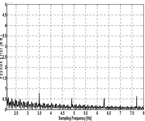
motion. This phenomenon lead to this problem. Fig. 5 and Fig. 6 show the Fast Fourier Transform (FFT) of tracking error at spindle speed of 1000 revolution per minute (rpm). The figures are tally with the value of amplitude tracking error with respect to the harmonic frequency as tabulated in Table II.
Figure 4. N-PID FFT Tracking Error at Spindle Speed of 1000 rpm
Figure 5. PID FFT Tracking Error at Spindle Speed of 1000 rpm
IV. CONCLUSION
In conclusion, NPID controller performs better than PID controller as a whole. The amplitude FFT tracking error of NPID at spindle speed of 1000 rpm, 2000 rpm and 3000 rpm are 0.7743, 0.6987 and 0.7151 micrometer respectively,
while for the case of PID, the maximum FFT tracking error are 0.7865, 1.327 and 0.787 micrometer respectively. Analyses on the harmonics content of the position tracking errors have shown the superiority of NPID controller. In addition, a step by step procedure to design a nonlinear PID controller has been discussed extensively. This will contribute a lot to the control community and for those who have interest to learn NPID controller. The contributions and benefits of the implementation of NPID controller in machine tools looks promising as it has the self tuning mechanism to compensate variable disturbances. It is recommended that the range of the spindle speed could be made wider to accommodate the demand for high speed machining.
ACKNOWLEDGMENT
This research is financially supported by the Centre of Excellence, Advanced Manufacturing Centre, Universiti Teknikal Malaysia Melaka (UTeM), with reference no. PJP/2012/AMC/Y00005.
REFERENCES
[1] Abdullah, L., Z. Jamaludin, Q. Ahsan, J. Jamaludin, N.A. Rafan, T.H. Chiew, K. Jusoff and M. Yusoff, "Evaluation on tracking performance of PID, Gain Scheduling and Classical Cascade P/PI controller on XY Table Ballscrew Drive System".World Applied Sciences Journal, vol. 21, pp. 01-10, 2013.
[2] E. A. Tannuri, A. C. Agostinho, H. M. Morishita and L. Moratelli Jr, “Dynamic positioning systems: an experiment al analysis of sliding mode control,” Control Engineering Practice, vol. 18, no.10, pp. 1121 – 1132, 2010.
[3] M. Du, Z. Zhang and Y. Liu, “ A research on expert fuzzy – PID fusion cont roller algorithm in VAV central air conditioning system,” in Third Int. Symposium on Intelligent Information Technology Application, Nan Chang, pp. 194 – 198, 2009.
[4] Reznik, L., Ghanayem, O. and Bourmistrov, A. “PID plus Fuzzy Controller Structures as a Design base for Industrial Applications.” Engineering Application of Artificial Intelligence. vol. 13, no. 4, pp. 419 – 430, 2000.
[5] Rahmat, M.F., Sy Najib Sy Salim, N.H. Sunar, Ahmad Athif Mohd Faudzi, Zool Hilmi Ismail and K. Huda, "Identification and nonlinear control strategy for industrial pneumatic actuator". International Journal of the Physical Sciences, vol. 7, no. 17, pp. 2566-2579, 2012. [6] Chih-Cheng, P., H. Thong-Shing, C. Shiaw-Wu, C. Ching-Yi, L. Yi-Ciao and W. Yao-Ting, "ZPETC path-tracking gain scheduling design and real-time multi-task flight simulation for the automatic transition of tilt-rotor aircraft". IEEE Conference on Robotics, Automation and Mechatronics, pp: 80-89. 2010.
[7] Abdullah, L., Z. Jamaludin, T.H. Chiew, N.A. Rafan and M.S. Syed Mohamed,"System identification of xy table ballscrew drive using parametric and non parametric frequency domain estimation via deterministic approach" . Procedia Engineering, vol. 41, pp 567-574, 2012.