INFRARED FOLLOWING CAR
NOR ANIS FADZILAH BINTI AMIRUDDIN
This Report Is Submitted In Partial Fulfillment Of Requirements For The Bachelor of Electronic Engineering (Industrial Electronics) with Honors
Faculty of Electronic and Computer Engineering Universiti Teknikal Malaysia Melaka
v
vi
Infrared (IR) Following Car”.
! " " #
" "
! # " "
vii
First of all, I would like to thank God for his blessing, and I would like to express my gratefulness to who had contributed in my final year project. I would like to begin my thanks giving with Mr. Amat Amir as my supervisor for support and guidance me throughout this project running and completing of this report.
Not forget also to thanksall those involved directly and indirectly helping me out during my PSM I & PSM II which I can’t state out every one of them. A special expression of gratitude is extended to everyone for their tolerance and patience in doing all the things. I must admit that they had enriched me in many ways and words alone are not enough to express my gratitude.
viii
1.1 Project Introduction 1
1.2 Project Objectives 2
1.3 Problem Statement 2
1.4 Scope of the Project 3
ix
2.1 DC Motor 5
2.2 Differential Drive 6
2.3 Working Theory of H‐Bridge 8
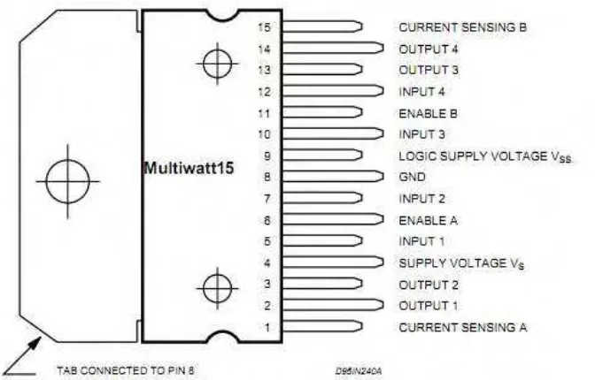
2.4 L298N Dual H‐Bridge Motor Driver 9
2.5 Infrared Light 12
2.6 Infrared Emitter 13
2.7 Infrared Receiver 14
2.8 NE555P Timer IC 16
2.9 LM7805 IC voltage regulator 18
2.10 Relay 21
3.1 Overall of Methodology Flowchart for PSM I and PSM II 25 3.2 Methodology Flowchart for PSM I (Project Part 1) 26 3.3 Methodology Flowchart for PSM II (Project Part 2) 28
4.1 Result 30
4.2 Discussion 37
V
x
1
!"# $# %&"# $
2
' !"# ( !"# !)
The objectives of this project are:
i. to design the schematic circuit diagram for the entire system ii. to simulate the schematic circuit.
iii. to fabricate the schematic circuit into the PCB board. iv. to test the effectiveness of the circuit on the PCB board.
From the above objective, the schematic circuit diagram for the system that must be designed are circuits for the pointer which is the emitter circuit, circuit for the receiver and circuit for the motor. Secondly, simulate the schematic circuit by using software is to make sure the circuit had been designed can work correctly. Thirdly, fabricate the schematic circuit into the PCB. Lastly, testing process is hold to make sure the product can work as planned.
* (+!, #-#!,!$#
3
. " /! 0 #1! !"#
Scopes of work of this project are:
i. study the theory of DC motor, IR transmitter and IR receiver.
ii. design the schematic circuit for DC motor, IR transmitter and IR receiver. iii. simulate the circuit using Proteus software.
iv. fabricate the PCB circuit. v. test the system.
2 !/ # # &"#& !
Chapter I, will discuss the introduction of the project. The introduction include sub topic of project introduction, objective of the project, problem statement of the project, scope of the project and the structure of this thesis.
In Chapter II, discussion on the literature review will be done. This literature review include the theory of the project such as the theory of DC motor that need to be use in this project, the theory of infrared emitter and receiver and lastly the components that need to be used in this project.
In Chapter III, project methodology will be discussed. This project methodology includes the sequence of the whole process in completing this project. The process began from PSM I until PSM II.
4
5
' #
Whenever talk about making a robot, the first thing comes to our mind is making the robot move on the ground. And there are always two options in front of the designer whether to use a DC motor or a stepper motor. When it comes to speed, weight, size and cost, DC motors are always preferred over stepper motors. There are many things which can do with the DC motor when interfaced with a microcontroller. For example can control the speed of the motor and can control the direction of rotation.
6
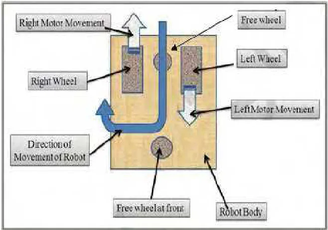
' ' 00! !$# -+ !
[image:19.612.164.493.215.446.2]By using two motors we can move our robot in any direction. This steering mechanism of robot is called as differential drive figure below shown the basic sketches, movement and the direction movement of the car.
7
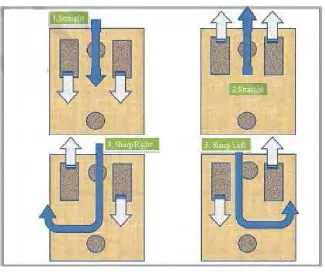
Figure 2.2: 4 types movement of the car. .
8
Table 2.1: A summary for the movement of the car.
31# # !0# # - !,!$#
Forward Forward Straight forward
Reverse Reverse Straight reverse
Forward Reverse Turn sharp to left
Reverse Forward Turn sharp to right
' * 4 $3 1! 5 0 ‐‐‐‐ %3!
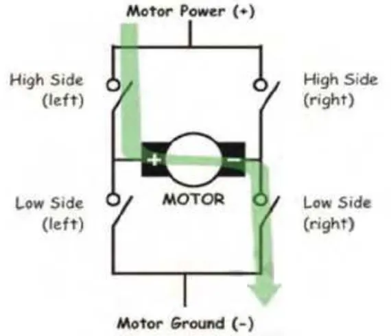
The name "H‐Bridge" is derived from the actual shape of the switching circuit which controls the motion of the motor. It is also known as "Full Bridge". Basically there are four switching elements in the H‐Bridge as shown in the figure below.
[image:21.612.186.471.402.647.2]9
As you can see in the figure above, there are four switching elements named as "High side left", "High side right", "Low side right", "Low side left". When these switches are turned on in pairs motor changes its direction accordingly. Like, if we switch on High side left and Low side right then motor rotate in forward direction, as current flows from power supply through the motor coil goes to ground.
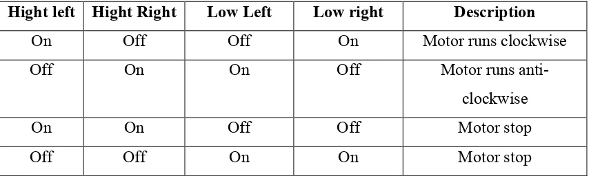
[image:22.612.121.548.333.461.2]Similarly, when you switch on low side left and high side right, the current flows in opposite direction and motor rotates in backward direction. This is the basic working of H‐Bridge. We can also make a small truth table according to the switching of H‐Bridge explained above.
Table 2.2: Truth table of the switching HEBridge.
31# +!0# 31# 31# 6 !0# 6 31# !)" /# $
On Off Off On Motor runs clockwise
Off On On Off Motor runs antiE
clockwise
On On Off Off Motor stop
Off Off On On Motor stop
' . '78 &-+ ‐‐‐‐ %3! # !
10
resistor. An additional supply input is provided so that the logic works at a lower voltage.
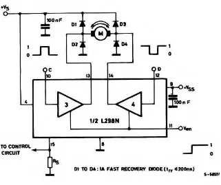
[image:23.612.161.497.287.502.2]L298N is a dual H‐Bridge motor driver, so with one IC we can interface two DC motors which can be controlled in both clockwise and counter clockwise direction and if you have motor with fix direction of motion. It can make use of all the four I/Os to connect to DC motors. L298N has operating supply voltage up to 46V, total DC current up to 4A and also had an over temperature protection.
11
Figure 2.4: Bidirectional DC Motor Control of L298N.