DOI:10.12928/TELKOMNIKA.v14i1.2710 4
Location and Position Determination Algorithm for
Humanoid Soccer Robot
Oei Kurniawan Utomo, Daniel Santoso, Saptadi Nugroho* Electronic and Computer Engineering Faculty, Satya Wacana Christian University,
Jalan Diponegoro 52 – 60 Salatiga 50711, (+62298) 311884 *Corresponding author, e-mail: [email protected]
Abstract
The algorithm of location and position determination was designed for humanoid soccer robot. The robots have to be able to control the ball effectively on the field of Indonesian Robot Soccer Competition which has a size of 900 cm x 600 cm. The algorithm of location and position determination uses parameters, such as the goalpost’s thickness, the compass value, and the robot’s head servo value. The goalpost’s thickness is detected using The Centre of Gravity method. The width of the goalpost detected is analyzed using the principles of camera geometry to determine the distance between the robot and the goalpost. The tangent value of head servo’s tilt angle is used to determine the distance between the robot and the ball. The distance between robot-goalpost and the distance between robot-ball are processed with the difference of head servo’s pan angle and compass value using trigonometric formulas to determine the coordinates of the robot and the ball in the Cartesian coordinates.
Keywords: robot, soccer, location determination, robot position
Copyright©2016 Universitas Ahmad Dahlan. All rights reserved.
1. Introduction
There are many techniques used to determine location of the robot and the ball on the field, for example: Voronoi based strategic positioning for robot soccer [1] and Monte-Carlo localization method applied in Multi-Cue localization for soccer playing humanoid robots [2]. The robot’s role on the field determination and its behavior has been researched by D.P. Playne in knowledge-based role allocation [3]. Similarly, Karen Petersen, Georg Stoll, and Oskar von Stryk developed a supporter behavior for soccer playing humanoid robots [4]. Hierarchical reactive control for humanoid soccer robot has been proposed by Sven Behnke and Jorg Stuckler [5]. The self-localization based on monocular vision for humanoid robot determines the robot’s location using a CCD camera [6]. Vision Based Self Localization for Humanoid Robot Soccer was implemented by Nuryono Satya Widodo and Arif Rahman [7] to create a robot soccer localization system. In this system, the robot’s location is used to take a decision whether or not the robot will kick the ball toward enemy team’s goal.
A soccer robot team must be able to play using a good strategy to win the game. Each robot must know the duty as a striker or a defender. The attacker is supposed to be on the attacking region position and scoring goal, while the defender is supposed to guard the defending region. The robot location and position determination becomes the problem in humanoid soccer robot. Therefore, the location and position determination algorithm is required so that the robot can know its duty and its working region.
In this paper we proposed an idea how to determine the coordinate of the robot and the ball in the field using the combination of the Centre of Gravity method and the Camera geometry analysis. The robot’s location in the Cartesian coordinate is used to create a strategy in the team. The goalpost that its coordinate has been known on the field is used as a landmark reference to determine the location of the robot on the field.
2. Research Method 2.1. Robot Control System
TELKOMNIKA
and ATMega324. The ATMeg orders to the KHR-3HV to call th
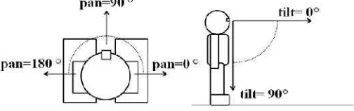
The Android Smartp and roll axis. The yaw axis is of 0° is always set to the attac
Figu
The head servo cons of pan and tilt servo is shown robot’s head have 1° in precis
Figu
2.2. Camera Geometry The principle of Came to the 2D dimension image pl projected on the image plane camera image processing [9-1
ISSN: 1693-6930
ega324 is used as the controller of the head se all the robot’s motion [8].
Figure 1. The robot control system
rtphone has the orientation sensor which has a yaw is used as 360° compass as shown in Figure 2. Th ack direction.
igure 2. The Android Smartphone compass
onsists of 2 servos: the pan servo and the tilt servo wn in Figure 3. The pan servo and the tilt servo whic
ision.
gure 3. The robot’s head servo: pan and tilt
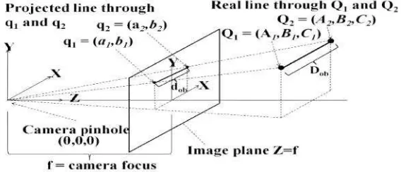
mera Geometry is projecting real object form the 3D plane. The farther an object from the camera the
ne. The pinhole camera model shown in Figure 9-10].
5
servo. It also gives
yaw axis, pitch axis, The compass value
vo. The range value hich are used in the
Figure 4. A line is p
A straight line that g the real length of Dob. The fo
length ofdob:
dob=
C
D
f
obWhere
dob = the projection lengt
f = the camera focus (c Dob = the real length of the
C = the distance betwee
2.3. The Robot Location on t 2.3.1. Goal detection
The algorithm of loc the image of the goalpost, the as a landmark reference beca goalpost detection is calculate OpenCV Library. The enemy using Android’s compass. The goal area. The 180° of the com The right and the left goalpos and the right goalpost’s COG goalpost’s COG value respecti
F
is projected to image plane using pinhole camera m
t goes through two points: Q1=(A1, B1, C1) and Q2=
following perspective equation is used to calcula
gth of the line(cm) (cm)
the line (cm)
ween camera focus and the line (cm)
n the Field
location and position determination uses informati he compass value, and the head pan value. The g cause it can be seen by the robot from any position ated using the Center of Gravity (COG) method [11 y team’s goal area and its own team’s goal area he 0° of the compass value shows the direction towa ompass value shows the direction toward the own ost are determined using the COG method. Figure
G value is located on the left side and the right s ctively.
Figure 5. The detection of the goalpost
a model
2=(A2, B2, C2) have
ulate the projection
(1)
TELKOMNIKA
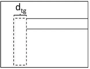
2.3.2. Robot-Goalpost Distan A goalpost that has image plane as shown in Fig fixed value, the rectangle will rectangle’s width and the dista the COG method and Android
The distance betwee
jrg = the distance betwee
f = the camera focus (c Dtg = the goalpost’s real wi
dtg = the projected goalpo
The goalpost’s dete The projected goalpost’s width the conversion value between
The camera resoluti object detected on the screen using the following formula:
R = the screen resolution dob = the width of objects d
L = the screen’s width (c
The camera focus of The screen resolution (R) is 4 calculated using Equation 2 respectively. The following equ
s cylindrical shape will be projected as a rectangle igure 6. If the distance between the robot and th will have the same width seen by the robot from ev
istance between the robot and the goalpost can be id OpenCv.
Figure 6. The detected goalpost
een the robot and the goalpost can be calculated u
ween robot and goalpost (cm) (cm)
l width (cm)
lpost’s width on image plane (cm)
tection process detects the width of the goalpost width on image plane in Equation 2 uses centimeter
en centimeter and pixel units is necessary.
lution which is used as the robot vision is 480 pi en with a length of dob will use pob pixels which c
rojection of an object in the image plane (pixel) tion (pixels)
ts detected on the screen (cm) (cm)
of f has 7.2 cm in length. The goalpost’s real wid is 480 pixels. The screen width (L) is 6.4 cm. The 2 and Equation 3 by substituting dob and pob
equation is the result of substituting Equation 2 and
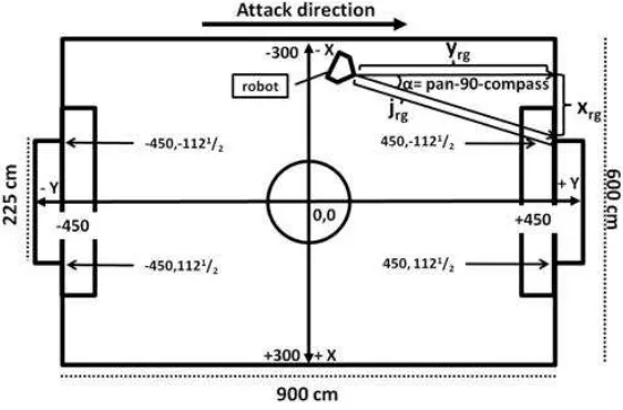
The robot’s Cartesian coordinate (xrgandyrg) relative to a goalpost as shown in Figure
7 is calculated using the trigonometric equation. The coordinate of the robot position on the field can be calculated by translating the robot’s relative coordinate based on the detected goalpost.
Figure 7. The distance between the ball and the robot
2.4. The Ball Location on the Field
The distance between the ball and the robot is calculated to determine the position of the ball on the field as shown in Figure 8 and Figure 9. The distance between the robot and the ball (jbr) is calculated using the following tangent equation:
γ
tan
r br
h
j
(robot’s height is 47 centimeters)
γ
tan
47
br
j
(5) Where
jbr = the distance between the ball and the robot (cm)
hr = the robot’s height (cm) = (47 cm)
γ
= the tilt value (degree)TELKOMNIKA
Figure 9. T
The coordinate of th ball’s relative coordinate using
2.5. The Positioning Algorith The striker and the algorithms. The attacker robo goal, while the defender robo supported by a communicati information about which robo striker robot holds the ball. Th
2.5.1. The Positioning Attack In attack condition th distance. The robot’s moveme
Figure 10. T
2.5.2. The Positioning Algorit In defense condition algorithm prevents striker rob defender robot will stay on the the line, it will retreat backward
ISSN: 1693-6930
9. The coordinate of the ball relative to the robot
f the ball position on the field can be calculated b ing robot’s coordinate on the field as shown in Figur
ithm for Attacker and Defender Robot
the defender robots require location and positi bot is supposed to be on the attacking region pos
bot is supposed to guard the defending region. cation process between the robots in a team
bot is holding the ball. The attack condition is ind The defense condition happens when the goalkeepe
ack Algorithm of Striker Robot
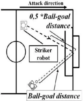
the striker robot will move forward up to the half of ment is drawn using yellow arrow as shown in Figur
. The Positioning Attack Algorithm of Striker Robot
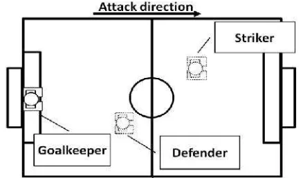
orithm of Striker Robot and Defender Robot tion the striker robot will retreat up to the center line
obot loses the ball at the front of the field. In att the behind of the field’s center line. If the defender ward. Figure 11 shows the robots configuration.
9
d by translating the ure 9.
sition determination osition and scoring n. This algorithm is m which contained indicated when the eper holds the ball.
of the goalpost-ball ure 10.
ot
Figure 11. The Positioning Defense Algorithm of Striker Robot
3. Results and Analysis
3.1. The Location Determination Algorithm of the Robot
Table 1 shows that there are error values at coordinate determination of the robot. The integer pixel values (ptg) and the error of α values cause the error of coordinate determination.
Table 2 shows the robot-goalpost distance according to the pixel value calculated using Equation 4. The farther the ball from the robot the bigger error value of jrgobtained.
Table 1. Robot’s Coordinate on The Field
Error value of α (°) Error value of jrg (%) Error value of coordinate (cm)
xrl yrl
Average 5.74 15 58.31 86.83
Standard deviation 2.22 8.33 45.92 82.26
Table 2. Thejrgand the pixel value
Pixel value (ptg) jrg(cm)
6 900
8 675
10 540
12 450
14 385.71
16 337,5
18 300
20 270
22 245.45
24 225
Compared to field which has 900 cm x 600 cm in size, the error value of the robot’s coordinate is about 9.72% in x coordinate and 9.65% in y coordinate.
3.2. The Location Determination Algorithm of The Ball
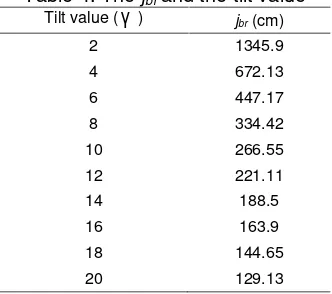
Table 3 shows that there are error values on coordinate determination of the ball. This is happened because of the integer value of the tilt γ and the errors of β values. Table 4 shows robot-ball distance according to the tilt value calculated using Equation 8. The farther the ball from the robot the bigger error value of jbrobtained.
Table 3. The Ball’s Coordinate on The Field
Error value of β (°) Error value of jbr(%) Error value of coordinate (cm)
xbr ybr
Average 5.48 27.94 62.35 91.18
TELKOMNIKA ISSN: 1693-6930 11
Table 4. Thejbrand the tilt value
Tilt value (
γ
) jbr(cm)2 1345.9
4 672.13
6 447.17
8 334.42
10 266.55
12 221.11
14 188.5
16 163.9
18 144.65
20 129.13
The error value of the ball’s coordinate is about 10.39% in x coordinate and 10.13% in y coordinate compared to field size.
3.3. The Positioning Algorithm for the Striker and Defender Robot
Table 5, table 6, and table 7 show the position determination algorithm error values of the striker and the defender robot. The positioning attack algorithm of the striker robot shown in Table 5 is affected by the robot location determination error values shown in Table 1 and the ball location determination error values shown in Table 3. The robot location determination error values shown in Table 1 affect the positioning attack and positioning defense algorithm of the striker and the defender robot shown in Table 6 and Table 7.
Table 5. The Positioning Attack Algorithm of Striker Robot
Error value of coordinate (cm)
x Y
Average 24.6 27.64
Standard deviation 13.45 9.91
Table 6. The Positioning Defense Algorithm of Striker
Error value of coordinate (cm)
x y
Average 26.7 54.02
Standard deviation 17.32 20.98
Table 7. The Positioning Algorithm of Defender
Error value of coordinate (cm)
x y
Average 25.94 14.08
Standard deviation 38.12 16.18
3.4. Computational Time
The computational time for executing the algorithm is measured using Android Logcat as shown in table 8 and table 9. The algorithm is run on 1 GHz processor and 512 RAM Android Smartphone.
Table 8. Computational Time for executing Robot Location Determination Algorithm
Time (ms)
Average 85.33
Table 9. Computational Time for executing Ball Location Determination Algorithm
Time (ms)
Average 72.67
Standard deviation 14.37
4. Conclusion
The humanoid soccer robot uses the algorithm of location and position determination to determine location and position of the robot and the ball on the field. The algorithm has the error tolerance values which are caused by the integer of pixel value, the integer of tilt value, and the error values of the difference between the compass and the pan value. The farther the ball from the robot the bigger error value of jrg and jbr obtained. The location determination’s
error values affect the position determination algorithm.
The location and position determination algorithm has 15% error value in average of robot-goalpost distance, while the robot-ball distance has 27.94% error value in average because the pixel values and the tilt values are integer. The average error value of robot-goalpost’s compass difference is 5.74°. The average error value of robot-ball’s pan-compass difference is 5.48°. Compared to field size, the error value of the robot’s coordinate is about 9.72% in x coordinate and 9.65% in y coordinate. The error value of the ball’s coordinate is about 10.39% in x coordinate and 10.13% in y coordinate compared to field size. The computational time required to determine the location of the robot has 85.33 milliseconds in average. The average of computational time required to determine the location of the ball is 72.67 milliseconds.
The number of pixels which represent the projected goalpost’s real width in image plane depends on the resolution of the camera. If the camera has high resolution then the tolerance error value of the robot and the goalpost distance will be reduced because there are many pixels used. The distance between the ball and the robot is represented by the tilt value. The servo which has higher precision of encoder will reduce the tolerance error value of the ball and the robot distance.
References
[1] S Kaden, H Mellmann, M Scheunemann, HD Burkhard. Voronoi Based Strategic Positioning for Robot Soccer. Proceedings of the 22nd International Workshop on Concurrency, Specification and Programming. Warsaw, Poland. 2013; 1032: 271-282.
[2] Hauke Strasdat, Maren Bennewitz, Sven Behnke. Multi-Cue Localization for Soccer Playing Humanoid Robots. In: Gerhard Lakemeyer, Elizabeth Sklar, Domenico G Sorrenti, Tomoichi Takahashi. RoboCup 2006: Robot Soccer World Cup X. Vol 4434. Springer Berlin Heidelberg. 2007: 245-257.
[3] DP Playne.Knowledge-Based Role Allocation.10th International Conference on Control Automation Robotics & Vision (ICARCV 2008). Hanoi. 2008; 10: 1616-1619.
[4] Karen Petersen, Georg Stoll, Oskar von Stryk. A Supporter Behavior for Soccer Playing Humanoid Robots. In: Javier Ruiz-del-Solar, Eric Chown, Paul G Plöger. RoboCup 2010: Robot Soccer World Cup XIV. Vol 6556. Springer Berlin Heidelberg. 2011: 386-396.
[5] Sven Behnke, Jorg Stuckler. Hierarchical Reactive Control For Humanoid Soccer Robot.International Journal of Humanoid Robotics.2008; 5(3): 375-396.
[6] Shih-Hung Chang, Chih-Hsien Hsia, Wei-Hsuan Chang, Jen-Shiun Chiang. Self-Localization Based on Monocular Vision for Humanoid Robot. Tamkang Journal of Science and Engineering. 2011; 14(4): 323-332.
[7] Nuryono Satya Widodo, Arif Rahman. Vision Based Self Localization for Humanoid Robot Soccer. TELKOMNIKA. 2012; 10(4): 637-644.
[8] Aditya Tri Sutrisno N, Yonas Aditya D, Bob William C, Ivan Kurniawan S, Choliq Budi S.Smart Phone Berbasis Android sebagai Kontrol Utama Robot Humanoid Soccer. The 2nd Indonesian Symposium on Robot Soccer Competition. Yogyakarta. 2014; 2: 54.
[9] RI Hartley, A Zisserman. Multiple View Geometry in Computer Vision. New York: Cambridge University Press. 2000: 153-154.
[10] Subhashis Banerjee. Camera Models and Affine Multiple Views Geometry. New Delhi: IIT Delhi. 2001: 2.
TELKOMNIKA ISSN: 1693-6930 13
Proceeding of Engineering International Conference “UNNES Conservation”. Semarang. 2013; 1: 142-146.
[12] Saptadi Nugroho, Darmawan Utomo. Rotation Invariant Indexing For Image Using Zernike Moments and R–Tree.TELKOMNIKA.2011; 9: 335.