accredited by DGHE (DIKTI), Decree No: 51/Dikti/Kep/2010 265
Nine-Phase Induction Motor Dynamic Model Based On
3x9 Transformation Matrix
Arman Jaya1,2, Soebagio1, Mauridhi Hery Purnomo1
1
Electrical Engineering Department, Sepuluh Nopember Institute of Technology (ITS), Surabaya Campus ITS Sukolilo, Surabaya
2
Electronic Engineering Polytechnics Institute of Surabaya (PENS), Surabaya e-mail: [email protected], [email protected], [email protected]
Abstrak
Analisis model dinamik motor induksisembilan fasa menjadi sulit karena berbasis pada matrik 9x9 dan sebuah rangkaian trafo terkopel secara magnetik. Agar model dinamik dalam bentuk qdn pada motor induksi sembilan fasa diperoleh dengan mudah, sederhana, cepat dan konsisten, maka analisis motor berbasis pada matrik transformasi 3x9 dan rangkaian ekuivalen motor model T. Matrik transformasi 3x9 disubstitusikan ke persamaan dalam bentuk abc agar diperoleh persamaan matrik dalam bentuk qdn.
Persamaan qdn menghasilkan rangkaian ekivalen qd yang sama dan rangkaian ekivalen n berbeda
dengan metode yang berbasis pada rangkaian trafo terkopel secara magnetik. Hasil simulasi menunjukkan bahwa karakteristik dinamik motor induksi 9-fasa yang berbasis pada model T dan rangkaian terkopel secara magnetik mempunyai respon dinamik yang sama untuk torka dan kecepatan.
Kata kunci:Matrik qdn ordo 3x9, rangkaian ekuivalen trafo model T, model dinamik qdn
Abstract
Analysis of the dynamic model nine-phase induction motor becomes difficult because based on a 9x9 matrix and a circuit of magnetically coupled transformer. In order to gain the qdn dynamic model of the nine-phase induction motors in easy, simple, quick and consistent way, the motor analysis will based on 3x9 transformation matrix and the equivalent circuit T model. The 3x9 transformation matrix qdn is substituted into the equation in form abc so that the matrix equation of qdn is obtained. Then qdn equation results a similar qd equivalent circuit, which has different methods n that is, based the circuit of magnetically coupled transformer. Simulation results show that the dynamic characteristics of 9-phase induction motor based on the T model and magnetically coupled circuit have similar torque and speed dynamic response.
Keywords: 3x9 matrik qdn, T model of motor equivalent circuit, qdn dynamic model
1. Introduction
A dynamic model of qdn for induction motor is required to determine the characteristics of the starting conditions of motor until it gets steady state. All dynamic induction models of motor have been introduced by using the analysis based on the circuit of 1-phase transformer, which is magnetically coupled by stator and rotor frequency references [1]-[3]. A single-phase transformer circuit can easily be converted into T models of electrical circuit by primary/secondary reference because it has similar frequency. Mutual reactance of transformer under steady-state conditions is constant because all primary and secondary winding of the transformer are silent.
Meanwhile, all the motor parameters obtained from testing the motor are based on the equivalent circuit T model. All parameters are expressed in the stator reference [6][7]. Mutual inductance can be obtained from the mutual reactance. Inductance of the stator and rotor can be obtained from leakage reactance the motor. At T model, the frequency of the rotor follows the stator frequency. Thus, there is a difference base in the analysis and testing of induction motors.
To generate dynamic model in term qdn, a square matrix is required according to the phase number of induction motors [8]. The transformation matrix 9-phase system has been introduced to anticipate the development of equipment that is considered to produce large power and small dimensions [9][13]. Transformation matrix for the 9-phase induction motors has 9x9 orders. Strong effort is required to obtain dynamic model of the 9-phase induction motors in term qdn.
A 3x9 matrix transformation can be used to simplify the form the analysis of the equation of 9-phase systems and can speed up calculations with the same result. Purpose of simplification can be achieved when a small number of matrix elements are used in the analysis. Transformation matrix used in the modeling of 9-phase induction motor has a line of three. Thus, the form of the transformation matrix 9-phase system is much simpler than the 9x9-transformation matrix.
Therefore, it will be simple, consistent and fast to obtain the analysis of the dynamic modeling of 9-phase induction motor using 3x9 transformation matrix based on the motor equivalent circuit T model. This dynamic model using qdn transformation is based on equivalent circuit T model by reference to the stator. Simulation is used to test the simple dynamic model by a synchronous reference frame. Motor load is made from full to half-full load. A dynamic response obtained from the simulations shows that there is no difference between the proposed model with the dynamic model by synchronous and rotor reference frame.
2. Research Method
2.1. A Dynamic Model of the nine-phase induction motors in term qdn
A nine-phase system in term abc that can represent nine-phase voltage, current and flux has the following equations:
t F
fa1 mcosω (1)
) 9 / 2 cos( 1F ωt π
fb m (2)
) 9 / 4 cos( 1 F ωt π
fc m (3)
) 3 / 2 cos(
2 F ωt π
fa m (4)
) 9 / 8 cos( 2 F ωt π
fb m (5)
) 9 / 8 cos( 2 F ωt π
fc m (6)
) 3 / 2 cos(
3 F ωt π
fa m (7)
) 9 / 4 cos(
3 F ωt π
fb m (8)
) 9 / 2 cos(
3 F ωt π
fc m (9)
Coordinate transformation of fabc to fqdn in term matrix that follows the pattern of Park.
cos
θ
sin θ
1
2
cos (
θ 2 π / 9) sin (θ 2 π / 9) 1
2
cos (
θ 4 π / 9) sin (θ 4 π / 9) 1
2
cos (
θ 2 π / 3) sin (θ 2 π / 3) 1
2
2
cos (
θ 8 π / 9) sin (θ 8 π / 9) 1
2
9
cos (
θ 8 π / 9) sin (θ 8 π / 9) 1
2
cos (
θ 2 π / 3) sin (
T( )
θ
θ 2 π / 3) 1
2
cos (
θ 4 π / 9) sin (θ 4 π / 9) 1
2
cos (
θ 2 π / 9) sin (θ 2 π / 9) 1
2
T
(10)
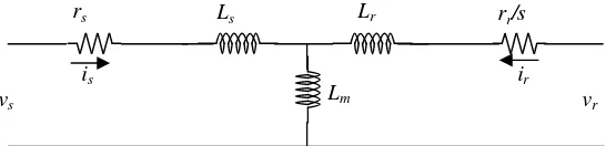
A circuit model of 9-phase induction motor consist of nine equivalent circuits of the same, and can be described in an equivalent circuit T model in a single-phase that opens at the rotor by stator reference as shown in Figure 1. Thus, all the parameters of the motor have the same references that are stator reference. Ls and Lr value is the combined value between
mutual inductance with inductance leakage stator or rotor. The voltage is expressed in deffrential matrix equation as follows:
Figure 1. Motor equivalent circuit T model
( )
( ) s
s s s
d t
t dt
λ
v r i (11)
( ) ( )
s r
r r
d t
t
s dt
r λ
v i (12)
In Equations 11 and 12, the resistances are diagonal matrix by order of 9x9 while the voltage, current and flux linkages are 1x9 order of column matrix. Whereλ1(t) =is(t)(Lls+ Lm) +
ir(t)Lmandλ2(t)=ir(t)(Llr+ Lm) +is(t)Lm. If Ls= Lls+ Lmand Lr= Lm+ Llrthen Equations 11 and
12 can be decomposed in the flux linkage as:
1( )t s( )t mr( )t
λ λ λ (13)
where,
0 0 0 0 0 0 0 0 0 0 0 0 0 0 0 0 0 0 0 0 0 0 0 0 0 0 0 0 0 0 0 0 ( ) ( ) 0 0 0 0 0 0 0 0 ( )
0 0 0 0 0 0 0 0 0 0 0 0 0 0 0 0 0 0 0 0 0 0 0 0 0 0 0 0 0 0 0 0
s s
s s
s s s s s
s s
s s
L L
L L
t t L t
L L
L L
λ
L i i
rs Ls Lr rr/s
Lm vr
vs
0 0 0 0 0 0 0 0 0 0 0 0 0 0 0 0 0 0 0 0 0 0 0 0 0 0 0 0 0 0 0 0 ( ) ( ) 0 0 0 0 0 0 0 0 ( )
0 0 0 0 0 0 0 0 0 0 0 0 0 0 0 0 0 0 0 0 0 0 0 0 0 0 0 0 0 0 0 0
m m
m m
mr mr r m r
m m
m m
L L
L L
t t L t
L L
L L
λ
L i i
and
2( )t r( )t ms( )t
λ λ λ (14)
where,
0 0 0 0 0 0 0 0
0 0 0 0 0 0 0 0
0 0 0 0 0 0 0 0
0 0 0 0 0 0 0 0
( ) ( ) 0 0 0 0 0 0 0 0 ( )
0 0 0 0 0 0 0 0
0 0 0 0 0 0 0 0
0 0 0 0 0 0 0 0
0 0 0 0 0 0 0 0
s s
s s
r r r s r
s s
s s
L L
L L
t t L t
L L
L L
λ L i i
0 0 0 0 0 0 0 0
0 0 0 0 0 0 0 0
0 0 0 0 0 0 0 0
0 0 0 0 0 0 0 0
( ) ( ) 0 0 0 0 0 0 0 0 ( )
0 0 0 0 0 0 0 0
0 0 0 0 0 0 0 0
0 0 0 0 0 0 0 0
0 0 0 0 0 0 0 0
m
m
m
m
ms ms s m s
m
m
m
m
L L
L L
t t L t
L L
L L
λ
L i i
Equations 11 and 12 are multiplied by T(s) and modify on the right of the equation
respectively to produce the following equation:
1
1
( )
( ) qdn s ( )
qdns qdns qdns s s s qdn
d t d θ
t θ θ θ t
dt dt
-1 λ T( )-1
v r i T( )T( ) T( ) λ (15)
2
2
( )
( ) ( )
qdnr qdn s
qdnr qdnr s s s qdn
d t d θ
t θ θ θ t
s dt dt
r -1 λ T( )-1
v i T( )T( ) T( ) λ (16)
Multiplication of transformation matrix in term qdn by its inverse matrix is done to produce identical matrix expressed as follows:
1
s s
1 0 0
( ) ( ) 0 1 0 I
0 0 1
T T (17)
s s
s s
s s
s 1
s
s s
s s
-sinθ cos θ 0
-sin (θ 2 π / 9) cos (θ 2 π / 9) 0
-sin (θ 4 π / 9) cos (θ 4 π / 9) 0
-sin (θ 2 π / 3) cos (θ 2 π / 3) 0
( ) 2
-sin (θ 8 π / 9) cos (θ 8 π / 9) 0
9
-sin (θ 8 π / 9) cos (θ 8 π / 9) 0
-s
s
d
dt ω
T
s s
s s
s s
in (θ 2 π / 3) cos (θ 2 π / 3) 0
-sin (θ 4 π / 9) cos (θ 4 π / 9) 0
-sin (θ 2 π / 9) cos (θ 2 π / 9) 0
where
θ
s
ω
st
, multiplication of transformation matrix in term qdn by its derivative inverse matrix produces as follows:s s
0 1 0
( )
( ) 1 0 0
0 0 0
s
d
dt ω
-1
s
T
T ω (18)
Equations 17 and 18 are substituted into equations 15 and 16 to obtain:
1
1
( )
( ) qdn ( )
qdns qdns qdns qdn
d t
t t
dt
λ s
v i ω λ
r
(19)
2
2
( )
( ) ( )
qdnr qdn
qdnr qdnr qdn
d t
t t
s dt
s
λ
v i ω λ
r
(20)
rqdnsandrqdnrare 3x3 diagonal matrixes
In Equations 19 and 20, the resistances are 3x3 diagonal matrix while the voltage, current and flux linkage are 1x3 column matrix. Thus, the flux linkage in term qdn is obtained from multiplication equations 13 and 14 with the transformation matrix of 9-phase system in term qdn such as:
-1 -1
qdn1 s s s s s s mr s s r
λ (t) = T(θ )L T(θ ) T(θ )i (t) + T(θ )L T(θ ) T(θ )i (t)
qdn1 qdns qdns qdn_mr qdnr
λ (t) = L i (t) + L i (t) (21)
-1 -1
qdn2 s r s s r s ms s s s
λ (t) = T(θ )L T(θ ) T(θ )i (t) + T(θ )L T(θ ) T(θ )i (t)
qdn2 qdnr qdnr qdn_ms qdns
λ (t) = L i (t) + L i (t) (22)
whereLqdns,Lqdnr,Lqdn_msdanLqdn_mrcan be expressed as:
0 0
0 0
0 0
s
s
s
L L
L
qdns
L ,
0 0
0 0
0 0
r
r
r L
L
L
qdnr
L and
0 0
0 0
0 0
m
m
m
L L
L
qdn_ms qdn_mr
L = L
Part derivative of Equations 19 and Equation 20 is replaced by 22, 23 and 18 (matrixs)
to obtain the equation as follows:
dt t t d t dt
t d
t ls qs ds m qs qr
qs s qs
)] ( i ) ( [i L ) (
ω
) ( i L ) ( i
r s
λ
dt t t d t dt t d t s qr qs m dr qr lr qr r qr )] ( i ) ( [i L ) ( ω ) ( i L ) ( i r s λ v (24) dt t t d t dt t d
t ds dr
m qs ds ls ds s ds )] ( i ) ( [i L ) ( ω ) ( i L ) ( i
r s
λ v (25) dt t t d t dt t d t s dr ds m qr dr lr dr r dr )] ( i ) ( [i L ) ( ω ) ( i L ) ( i r s λ v (26) dt t t d dt t d
t ns nr
m ns ls ns s ns )] ( i ) ( [i L ) ( i L ) ( i
r
v (27) dt t t d dt t d t s nr ns m nr lr nr r nr )] ( i ) ( [i L ) ( i L ) ( i r v (28)
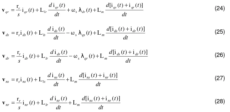
From equations 23 to 28 can be established equivalent circuit of 9-phase induction motors in qdn model as shown in Figure 2a, 2b and 2c.
Electromechanical torque generated in the motor in termqdncan be expressed as:
)) ( )
( (
2 i t i t
p
Te λqrdr λdrqr (29)
Substitute part of flux rotor linkage in Equation 22 into Equation 29 to obtain a new equation as in Equation 30.
)) ( ) ( (
2L i i t i i t
p
Te m qsdr dsqr (30)
(a) The motor equivalent circuit in termq
(b) The motor equivalent circuit in termd
(c) The motor equivalent circuit in termn Figure 2. The motor equivalent circuit in termqdn
rs Lls Llr rr/s
Lm vnr
vns
iqs iqr
rs Lls Llr rr/s
Lm vqr
vqs
+ - - +
iqs iqr
ωsλdr ωsλds
rs Lls Llr rr/s
Lm vdr
vds
- +
+-ids idr
Electromechanical torque equation is also obtained from the mechanical equations by neglecting rotor friction and load friction as follows:
m L
e T J
T
θ (31)
where: Jis load inertia TLis load torque
2.2. Simulation
Equations 19 and 20 are the basic simulation of 9-phase induction motors. However, the desired result is the flux linked to the stator and the rotor, so that Equations 19 and 20 are substituted into the qdn modified equations 32 and 33 as follows:
) ( )
( )
(
t t
dt t d
qds qds
s qds qds
λ ω
i r v
λ
s
(32)
) ( )
( )
(
t t
s dt
t d
qdr qdr
r qdr qdr
λ ω
i r v
λ
s
(33)
whereωsexpressed as:
0 0 0
0 0
0 0
s s
ω ω
s
ω (34)
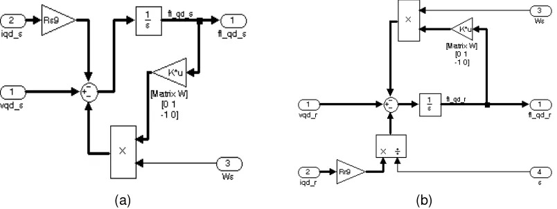
Equations 32, 33, and 34 are forms of the basis of the simulation model in term qdn for stator flux and rotor flux of 9-phase induction motor as shown in Figure 3. All initial conditions are zero in motor Equation.
(a) (b)
Figure 3. Motor flux linkage, (a) Stator flux linkage, (b) Rotor flux linkage
From Equations 21 and 22, the flux can be expressed in term current when λ = Li, so by combining both the stator flux and the rotor flux equations and then insert the inductance values in term qdn the equation 24 is obtained.
nr dr qr ns ds qs m r m m r m m r m m m s m m s m m s nr dr qr ns ds qs qdn i i i i i i L L L L L L L L L L L L L L L L L L 0 0 0 0 0 0 0 0 0 0 0 0 0 0 0 0 0 0 0 0 0 0 0 0 λ λ λ λ λ λ λ (35)
Simulations obtained from Equation 36 can be seen in Figure 4. Figure 4 has already shown the stator flux and rotor flux act as input, while the stator and rotor current act as output.
nr dr qr ns ds qs m r m m r m m r m m m s m m s m m s nr dr qr ns ds qs qdn L L L L L L L L L L L L L L L L L L i i i i i i λ λ λ λ λ 0 0 0 0 0 0 0 0 0 0 0 0 0 0 0 0 0 0 0 0 0 0 0
0 1 λ
i
(36)
Figure 4. Simulation of motor current as a function of the motor flux
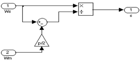
Simulation of the motor is not complete before the slip is obtained. The slip that occurs in motor is according to the following equation 37:
s m s
s
ω
ω
ω
(37)wheremis the rotor angular velocity in electrically
When the input is synchronous rotor speed, the output is the slip. Simulation of slip model can be seen in Figure 5.
Figure 5. Simulation of slip as a function angular velocity
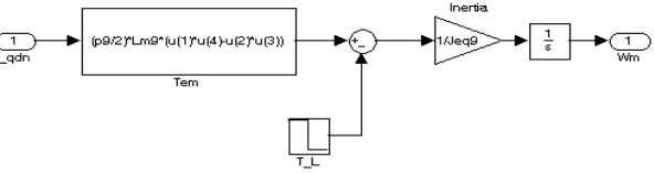
Figure 6. Simulation of the mechanical angular velocity as a function of torque
Simulation of the induction motor can be made by combining simulation of motor parts to form a simulation of 9-phase induction motor as a whole. Simulation of induction motor is shown in Figure 7.
Table1.Parameter induction motor [15]
Parameters Nine-phase induction motor Rs 0,47Ω
Xs 0,69Ω
R’r 0,53Ω
X’r 0,69Ω
Xm 13,42Ω
Vs 73V
Figure 7. Simulation of 9-phase induction motor based on equivalent circuit T model
3. Results and Discussion
In this paper, the induction motor is a nine-phase induction motor with very low voltage. This motor was developed from a 3-phase induction motor for electric car need with the goal of a high level of safety. Motor data are taken from previous research as presented in Table 1. The number of poles and the inertia motors respectively are 2 and 0.025 kg-m2.
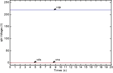
frames that have been developed previously are used as validation. Source voltage of 9-phase induction motor is 9-phase voltage symmetry that is divided in groups of 3-phase, each different phase angle of 40° as shown in Figure 8. After that, the source voltage is transformed to the coordinates of the reference that the stator qdn can generatevq = 225 V,vd = 0 V andvn= 0 V as shown in Figure 9.
Stator and rotor produced currents in term qdn can be seen in Figures 10 and 11. Rotor currents show a negative value to the stator current, which means that the actual current is unidirectional due to the opposite rotor current to the direction given. Just at the start, the stator current (id) is higher than rotor current (iq). Then when approaching steady-state current, for a
moment, the stator current (id) turns lower than the rotor (iq) current. At steady-state with full
load, the stator current (id) is higher than the iq current. When the stator current (id) is still lower
than iq current and does not change position despite the motor load, the (id) is lowered to
half-full load.
Figure 8.vabcoutput voltage which is the result of the transformation of the term vqdnby= 0
Figure 9.vqdnoutput voltage which is the result of the transformation of the term vabcby=s
Figure 10. Motor currentiqdnby=s
0 5 10 15 20
-100 -50 0 50 100
Times (ms)
In
p
u
t
v
o
lta
g
e
(V
)
va1 va2 va3 vb1 vb2 vb3 vc1 vc2 vc3
0 1 2 3 4 5 6 7 8 9 10 11 12 13 14 15 16 17 18 19 20
0 50 100 150 200 250
Times (s)
q
dn
V
ol
ta
ge
s
(V
)
vns vds
vqs
0 1 2 3 4 5 6 7 8 9 10 11 12 13 14 15 16 17 18 19 20
-150 -100 -50 0 50 100 150
Times (s)
Iqd
M
o
to
r
C
u
rr
e
n
t
(A
)
Ids
Iqs
Figure 11. Motor currentiqdnby=sin the area of load changes (from full to half load)
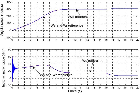
Characteristics of 9-phase induction motor obtained from the simulation for synchronous reference frame can be seen in Figure 12 and 13. The transient response of angular speed of the proposed method is no over-shoot and in the same time achieving steady-state conditions at full load compared to models using synchronous reference and rotor reference. The load decrease does not cause oscillations in response of angular speed. Meanwhile, the transient response of the oscillating torque equally and the same time achieve steady-state conditions at full load compared to the synchronous reference frame. The load decrease does not cause oscillations in response of torque and angular speed. The proposed model has the same maximum torque of the models using synchronous reference. At steady-state with full load, the torque generated is similar between the proposed motor model with a model that uses synchronous reference and rotor reference. In areas of change, from full to half load, the torque on both motors is down and the speed is faster. Both torque and speed responses have a large value. Both motors have no overshoot and oscillation when the load changes. They remain the same in next steady-state conditions.
Figure 12. Characteristics of torque and angular speed vs. time in the refference frames
13 14 15 16 17
-25 -20 -15 -10 -5 0 5 10 15 20 25
Times (s) Iqd
M
o
to
r
C
u
rr
e
n
t
(A
)
Ids Iqs
Idr
Iqr Load changing time
0 1 2 3 4 5 6 7 8 9 10 11 12 13 14 15 16 17 18 19 20
-100 0 100 200 300 400
A
n
g
u
la
r
s
p
e
e
d
(
ra
d
/s
e
c
)
0 1 2 3 4 5 6 7 8 9 10 11 12 13 14 15 16 17 18 19 20
-20 0 20 40 60 80
Times (s)
In
d
u
c
ti
o
n
m
o
to
r
to
rq
u
e
(
N
-m
)
Ws refference
Ws and Wr refference
Ws refference
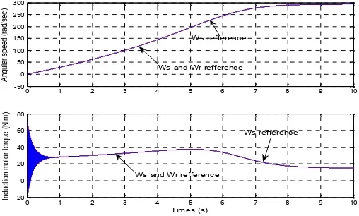
Figure 13. Characteristics of torque and angular speed vs. time by the refference framesin
the starting area
4. Conclusion
Analysis of qdn dynamic model of 9-phase induction motor indicates that at the qd equivalent circuit has no difference with the previous method, but in the neutral equivalent circuit (n), there is a parameter mutual inductance between the stator to the rotor. From the simulations, it can be seen that the synchronous reference frame, compared to the previous method, shows the characteristic torque and angular speed of 9-phase induction motor reaching steady-state in the same time to produce the same maximum torque. The transient response does not occur of oscillation and over-shoot. Dynamic characteristics of 9-phase induction motor based on the T model and magnetically coupled circuit have similar torque and speed dynamic response. In the circuit-based model of T, torque and angular speed response with similar maximum torque achieve steady-state rather than the model based on magnetically coupled circuit.
References
[1]. Bimal K Bose. Modern Power Electronics and AC drives. Prentice Hall PTR. 2002. [2]. R Krishnan. Electric Motor Drives. Prentice Hall. 2001.
[3]. Ned Mohan. Electric drives an integrated approach. MNPERE. Minneapolis. 2003. [4]. Paul C Krause. Analysis of Electric Machinery.MNPERE. Minneapolis. 2004.
[5]. Victor G, Sergey EL. Micromechatronics, Modeling, Analysis, and Design With Matlab. Florida: CRC Press. 2004.
[6]. Saffet Ayasun, Chika O Nwankpa. Induction Motor Tests Using MATLAB/Simulink and Their Integration Into Undergraduate Electric Machinery Courses.IEEE Trans. On Education. 2005; 48(1): 37– 45.
[7]. Soebagio. Teori Umum Mesin Listrik. Surabaya: CV. Srikandi. 2008.
[8]. Bambang Sujanarko, M Ashari, Mauridhi HP. Improve Voltage of Cascade Inverter Using Sine Quantization Progression.TELKOMNIKA. 2010; 8(2): 123-130.
[9]. E Levi, et al. Multiphase induction motor drives – a technology status review.IET Electr. Power Appl. 2007; 1(4): 1996–2005.
[10].Zheng Yu, Kang Min. Analysis of Nine phase Induction Motor Under Unbalance Supply. Journal of Mechanical & Electrical Engineering. 2011; 28(8): 1006–1011.
[11].Libo Zheng, et al. Dual-Plane Vector Control of a Five-Phase Induction Machine for an Improved Flux Pattern. IEEE Trans. On Ind. Electronics. 2008; 55: 1996–2005.
[12].Ayong Hiendro. A Quantities Method of Induction Motor under Unbalanced Voltage Conditions.
TELKOMNIKA. 2010; 8(2): 73-80.
[13].L Parsa, H A Toliyat. Sensorless Direct Torque Control Of Five-Phase Interior Permanent-Magnet Motor Drives.IEEE Trans. Ind. Appl.2007; 43(4): 952–959.
[14].Arman Jaya, Soebagio, Mauridhi HP. Transformation Terms abc To qdn For 9-Phase System With 3x9 Matrix.Academic Research International. 2012; 2(1): 90–101.
[15].Arman Jaya, Soebagio, Mauridhi HP. Steady-State Characteristics of Nine-Phase Induction Motor Squirrel Cage Rotor by Very Low Voltage. International Journal of Academic Research. 2012; 4(3): 46–57.
0 1 2 3 4 5 6 7 8 9 10
-50 0 50 100 150 200 250 300
A
ng
ul
ar
s
pe
ed
(
ra
d/
se
c)
0 1 2 3 4 5 6 7 8 9 10
-20 0 20 40 60 80
Times (s)
In
du
ct
io
n
m
ot
or
t
or
qu
e
(N
-m
)
Ws refference
Ws and Wr refference
Ws refference