Jefferson Lab FY03 R&D Activities in Support of RIA
J. Delayen, E. Daly, K. Davis, L. Harwood, A. Hofler, C. Hovater Thomas Jefferson National Accelerator Facility
Abstract
In FY 03 Jefferson Lab received funding for generic R&D activities in support of RIA. This effort is in two areas: LLRF control system development, and testing of the SNS cryomodules to assess their suitability for RIA. As part of the first task we are developing, in collaboration with DESY, a model of the LLRF control system including the cavity and the rf system. As part of the second task we are performing a number of measurements (microphonics level and spectrum, Lorentz and piezo tuner transfer functions, tuner resolution, coupler capability, etc.) on the medium beta SNS cryomodules that are under production at JLAB. Results of these activities will be presented.
Category: R&D for Main Linac
Introduction
In FY 2003, Jefferson Lab submitted a work proposal to DOE titled: Development of a Low-Level RF Control System and Integrated Test of a RIA Driver Cryomodule System. This work proposal was only partially funded and our activities have focused on two areas: modeling of an rf control system and investigation of new control techniques, and
measurements on the SNS cryomodules under production at JLab to assess their suitability for the RIA driver linac.
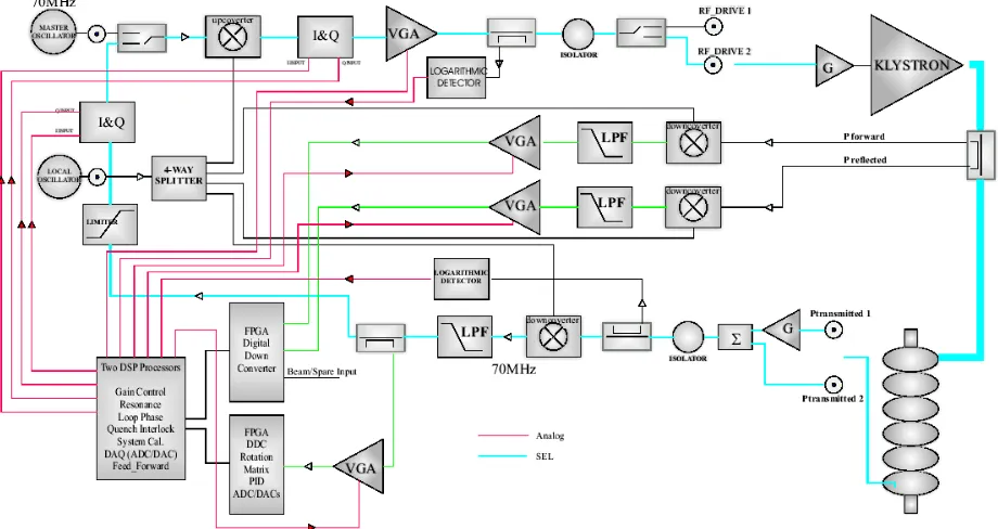
LLRF Control System Development
Although they are different accelerators, from an rf control system perspective, the RIA driver and the JLab 12 GeV upgrade present similar issues and will benefit from similar solutions. Both will operate in a regime that is new in the SRF accelerator technology: they are comprised of a large number of high-Q, lightly (but non-negligibly) beam-loaded superconducting cavities running cw. The dynamic behavior of the rf field in the
accelerating structures will be affected both by the beam loading and by ambient
microphonics. The similarity and synergy between those two projects has allowed us to make progress toward both by combining resources.
The draft of the RIA requirements document has greatly benefited from a similar document written for the 12 GeV upgrade.
The RIA project has also benefited from Jefferson Lab’s collaboration with Cornell and DESY. In periodic videoconference meetings, various topics pertaining to the
failure analysis. This periodic exchange of information on software and hardware issues and pooling of resources and expertise has been beneficial to all involved.
We have also participated in the “redesign” of the SNS LLRF system. It is the most modern LLRF system that is under development and production, and its design will benefit both the RIA and the 12 GeV Upgrade LLRF systems.
Jefferson Lab is using the MATLAB/Simulink library for RF systems [1] developed for TTF to develop a model for the RIA SRF cavities. This model is generic and is applicable to a wide range of superconducting accelerators. The library includes beam loading, Lorentz force detuning effects, and klystron saturation characteristics. It supports systems operating in a self-excited loop or as a generator driven resonator under I/Q or amplitude and phase control. We are at present incorporating into the model data obtained from measurements on SNS cavities [2], and as experimental data becomes available, the model will be updated accordingly. As opportunity arises data obtained from other RIA cavities will also be incorporated into the model. A future enhancement to the mechanical portion of the cavity model is to develop a description of microphonics using a statistical white noise process. The model will also be used to investigate electronic damping of
mechanical modes [3].
The goal of this effort, if continued in future years, is to produce a cost-effective LLRF control system that will be applicable to a wide range of accelerators with only minor modification of the hardware and customization of the software.
Figure 2: Simulink model of the LLRF control system.
As mentioned above, the RIA driver linac is only lightly beam loaded. Consequently, the rf power required for phase and amplitude control will be mostly determined by the
window inside which the deviation of the cavity frequency from the reference frequency is expected to reside. This deviation has two components: a static or slow varying
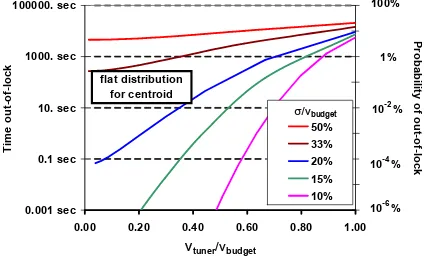
component due to the stability of the tuners and pressure fluctuations, and a dynamic component due to microphonics. The larger the control window, the smaller the probability that a cavity would lose lock, but also the larger the cost of the installed rf power sources (klystrons, IOT’s, etc.). We have developed a model that relates the size of the control window, the accuracy with which the average frequency of the cavity can be set with the tuners, the level of microphonics, and the probability that a cavity would be out of lock [4]. The model relies on a number of assumptions:
1) Excursions of the cavity’s frequency away from the reference frequency can be separated into two classes: those slow enough to be corrected by the tuner and those that occur so quickly that the tuner cannot compensate for them
2) The time probability distribution of the fast events can be characterized by a Gaussian with standard deviation σ
3) The centroid of the Gaussian drifts uniformly within the tuner activation window of ±νtuner of the rf frequency.
Based on this model, which is illustrated in Fig. 3, reasonable numbers for the tuner accuracy, rms microphonics, and control window are +/- 4 Hz, 3.5 Hz, and +/- 25 Hz, respectively.
0.001 sec 0.1 sec 10. sec 1000. sec 100000. sec
0.00 0.20 0.40 0.60 0.80 1.00
ν
tuner/νbudgetFigure 3: Probability of a single cavity being out-of -lock during one day as a function of tuner activation window (+/- νtuner) and rms microphonics (σ), normalized to the control
window (+/- νbudget).
Measurements on the SNS Cryomodules
Medium-β SNS cryomodules are now in full production at JLab, and, although SNS and the RIA driver linac are quite different accelerators – the former being a single species, single charge state, low-Q, heavily beam loaded pulsed accelerator, and the latter being a multiple species, multiple charge state, high-Q, lightly beam loaded, cw accelerator--, since they cover roughly the same velocity range, the SNS cryomodules may be appropriate for use in RIA. We, therefore, have conducted a series of tests on each SNS cryomodule to-date to assess their suitability to RIA. In particular, we have performed measurements on the fundamental rf power coupler, the mechanical and piezo tuners, and on the dynamic behavior of the cavities’ frequency.
Fundamental rf power coupler
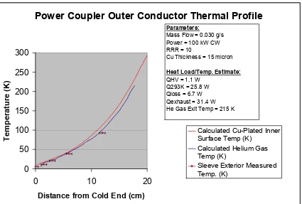
than the expected RIA requirement of 20 kW or less. The cavity functioned acceptably during the test.
As shown in Fig. (4) the measured temperatures along the helium-gas-cooled outer
conductor were in good agreement with predictions and calculations. Tests to date indicate that the high power coupler designed for SNS will be applicable to RIA.
Power Coupler Outer Conductor Thermal Profile
0
Distance from Cold End (cm)
Tem
Cu Thickness = 15 micron
Heat Load/Temp. Estimate:
Figure 4: Calculated and measured temperature profile during cw operation of an SNS coupler
Mechanical frequency tuner (resolution and hysteresis)
Cavity #1 (M03) Tuner Hysterisis
-10000 -9000 -8000 -7000 -6000 -5000 -4000 -3000 -2000 -1000 0
Step Position
Figure 5: Range and hysteresis of an SNS mechanical tuner
The RIA requirements are substantially different. Because of the much-reduced bandwidth, the most important requirement is the ability to achieve a predetermined frequency with high accuracy without backlash and deadband. This was measured by operating the stepper motor back and forth in a square wave pattern and reducing the step size until no change in the cavity frequency was observed. As indicated in Fig. (6) a deadband-free operation of <1 Hz was observed when the mechanical tuner was operated at a frequency of 0.1Hz, satisfying the stringent RIA requirements.
M02 Cav 3 Mech Tuner Resolution, 1 Half-step motor drive
Piezo frequency tuner (resolution and hysteresis)
For the piezo tuner we have found from measurements on several cryomodules that the range is greater than 3 kHz, the hysteresis is ~ 500 Hz and the resolution is less than 1 Hz. To determine the piezo hysteresis, the voltage is ramped from 0 to 800 V and back. The hysteresis is the change in frequency at a given piezo voltage.
The deadband of the piezo tuner was measured in a way similar to the mechanical tuner. It was driven with a square wave voltage and the amplitude was reduced until no cavity frequency change was observed. The deadband was measured to be <1Hz satisfying the RIA requirements.
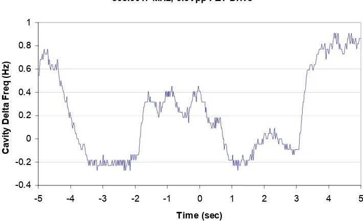
Piezo Tuner Minimum Resolution Test, SNS M01 Cavity 1 805.0017 MHz, 0.3Vpp PZT Drive
-0.4 -0.2 0 0.2 0.4 0.6 0.8 1
-5 -4 -3 -2 -1 0 1 2 3 4 5
Time (sec)
Cavity Delta Freq (Hz
)
Figure 7: Frequency of a cavity when the piezo tuner is operated at 0.2 Hz. Resolution and deadband are <1Hz
We have also measured the microphonics level generated by the operation of the piezo tuner. Operation of the piezo tuner with a square wave voltage generates microphonics similar in magnitude to the step change in frequency. In order to reduce the microphonics to about ¼ of the change in frequency, the voltage change from initial to final value needs to be accomplished in at least 10 msec [5].
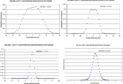
Probability density of microphonics
measurements, where the slow drifts (<1Hz) have been removed, are shown in Fig. (8). We also found large temporal variations for individual cavities where the level of microphonics varied dramatically in time, presumably due to the dynamic state of the refrigerator and cryogenic distribution system. Oscillations of the order of 50 Hz were sometimes observed.
At present it is not possible to conclude that the SNS cryomodule design is compatible with the RIA microphonics requirements.
Figure 8: Probability densities of microphonics measured on several SNS cavities
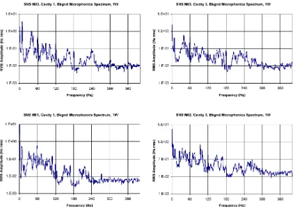
Frequency spectrum of microphonics
We also performed extensive measurements of the frequency spectrum of microphonics on many cavities. This information would later be incorporated in the LLRF model described earlier. The data shows rich frequency spectra and, as was the case for rms level we found large differences in the frequency spectra of microphonics in different cavities. This implies that the LLRF control system will have to be flexible and adaptable, and possibly customizable for each individual cavity
Figure 9: Spectra of microphonics measured on several SNS cavities
Lorentz transfer function
Transfer functions from rf field modulation to cavity frequency have been measured on the medium-β SNS cavities. This data will then be incorporated in the LLRF model described earlier and will be included in the software of the LLRF control system. We anticipate performing the same measurements on all the cavities that will be used in the RIA driver from the lowest to the highest β as the opportunity arises.
Unlike low-β structures, medium-β structures show a rich and complex mechanical mode spectrum that can vary significantly from one cavity to the next. As a consequence we expect that a LLRF control system for those cavities, when they are operation in a high-Q mode will require a substantial amount of customization.
Cavity Position 2, Lorentz Transfer Function (5MV/m, 805.000 MHz)
M:\asd\asddata\CMTF\M03\Cav 2 Lorentz Mech Modes\Lorentz Xfer M03_2.xls
Cavity Position 1, Lorentz Transfer Function (5MV/m, 805.006 MHz)
25
M:\asd\asddata\CMTF\M03\Cav 1 Lorentz Mech Modes\Lorentz Xfer M03_1.xls
Figure 10: Amplitude (red) and phase (blue) of the transfer function from cavity field modulation of cavity frequency modulation for 2 SNS cavities.
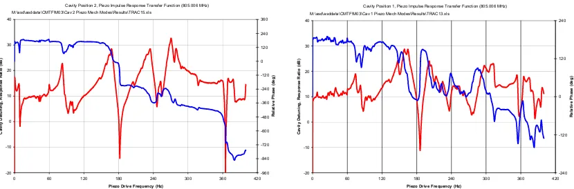
Piezo tuner transfer function
One of the possible means of reducing the microphonics-induced frequency variations is to counteract them with an active piezo tuner. The SNS cavities are equipped with piezo tuners to compensate for the dynamic Lorentz detuning caused by pulsed operation. If such piezo tuners are used to compensate for microphonics then complete transfer functions from piezo drive to cavity frequency are required. We have measured such transfer functions and examples are shown in Fig (11).
The variability between cavities was even more pronounced than in the case of the Lorentz transfer functions.
An attempt was made at using the piezo tuner in a simple proportional feedback system to reduce the microphonics-induced frequency variations. This was not successful as some mechanical modes were reduced while some were amplified. This was not unexpected given the measured transfer functions. For such a feedback system to be effective,
compensators –possibly customized for individual cavities—will need to be developed and incorporated in the feedback system.
Cavity Position 2, Piezo Impulse Response Transfer Function (805.006 MHz)
-20
M:\asd\asddata\CMTF\M03\Cav 2 Piezo Mech Modes\Results\TRAC15.xls
Cavity Position 1, Piezo Impulse Response Transfer Function (805.006 MHz)
-20
M:\asd\asddata\CMTF\M03\Cav 1 Piezo Mech Modes\Results\TRAC13.xls
Future Activities
In future years JLab’s activities in support of RIA will concentrate of the development of a LLRF control system for all of RIA’s superconducting cavities, and on performing an integrated test of a RIA driver accelerator building block (cryomodule, LLRF control system, and rf power).
The similarity between the LLRF control system requirements of RIA and the 12 GeV upgrade implies that both programs would benefit from a common development effort. As part of this activity, we expect to perform similar measurements on all the superconducting cavities and cryomodules developed for the RIA program. Such measurements have already been conducted at ANL.
Because of its extensive development and testing infrastructure (currently applied to the SNS project), as well as its wide-ranging expertise, JLab is uniquely positioned to perform a complete, integrated development and test of a RIA cryomodule. This would include a cryomodule, a LLRF control system and an rf power source.
References
[1] A. Vardanyan, V. Ayvazyan, and S. Simrock, “An Analysis Tool for RF Control for Superconducting Cavities,” EPAC’02, Paris, June 2002, pp. 1673-1675.
[2] A. Hofler, J. Delayen, C. Hovater, and S. Simrock, “RF System Modeling for the JLab 12 GeV Upgrade and RIA,” to be presented at SRF2003 Workshop,
Lübeck/Travemünde, September 2003.
[3] J. R. Delayen, “Electronic Damping of Superconducting Cavities”, PAC’01, Chicago, June 2001.
[4] J. R. Delayen, L. H. Harwood, “Determination of Low Level RF Control Requirements for Superconducting Cavities from Microphonics Measurements”, PAC’03, Portland, OR, 12-16 May 2003.