Faculty of Electrical Engineering
FEASIBILITY STUDIES AND SYSTEM PERFORMANCE OF 2 MW
SOLAR PV PLANT AT UTeM
Hamza Z. M. Abunima
Master of Electrical Engineering
(Industrial Power)
FEASIBILITY STUDIES AND SYSTEM PERFORMANCE OF 2 MW SOLAR PV
PLANT AT UTeM
Hamza Z. M. Abunima
A dissertation
submittedIn partial fulfilment of the requirements for the degree of Master of Electrical Engineering (Industrial Power)
Faculty of Electrical Engineering
UNIVERSITI TEKNIKAL MALAYSIA MELAKA
DECLARATION
I declare that this dissertation entitle “Feasibility Studies and System Performance of 2 MW Solar PV Plant at UTeM” is the result of my own research except as cited in the references. The dissertation has not been accepted for any degree and is not concurrently submitted in the candidature of any other degree.
APPROVAL
I hereby declare that I have read this dissertation and in my opinion this dissertation is sufficient in terms of scope and quality for the award of Master of Electrical Engineering (Industrial Power).
DEDICATION
To my family who has supported me significantly, a special feeling of gratitude to my great parents Zohdi Abunima and Najwa Alswerke who have supported me through my life. I will always appreciate their sacrifices for me. Their encouragement had a main role in achieving my goals and wishes throughout my career. I am extremely proud of them.
I would like to thank my sweetheart Somaya Abunima for her wholehearted and unconditional support. She always pushes me to be the best I could be. She had stood beside me in my alienation.
i ABSTRACT
ii
ABSTRAK
Fotovolta (FV) menjadi semakin penting sebagai salah satu sumber tenaga boleh
diperbaharui yang paling meyakinkan untuk menangani cabaran perubahan iklim.Empat sistem
FV dipasang di UTeM iaitu Polycrystalline, Thin Film, HIT dan Monocrystalline dengan jumlah
kapasiti sebanyak 23.88kW. Oleh yang demikian, kajian ini bertujuan untuk menilai rekabentuk
elektrik lengkap loji kuasa 2 MW solar FV tersambung grid yang bertempat di UTeM Melaka.
Untuk mencapai matlamat ini, kaji selidik tapak telah dilakukan untuk meninjau keadaan lokasi
pemasangan serta jarak ke titik sambungan yang berkemungkinan. Di samping itu, data
meteorological boleh diperolehi dari perisian Meteonorm. Sistem FV yang sedia ada di UTeM
digunakan untuk mengambil data meteorologi di tapak. Seterusnya, orientasi modul FV, saiz
kumpulan FV dan saiz kabel ditentukan berdasarkan data yang diperolehi. penyongsang dan
alatubah yang digunakan untuk loji FV ini adalah dicadangkan dan seterusnya dikaji. Kajian ini
memperlihatkan faktor-faktor utama yang memberi kesan kepada prestasi sistem kuasa solar FV.
Selain itu, nisbah prestasi dan hasil spesifik loji yang dicadangkan akan dikira untuk
mengesahkan kesahihan rekabentuk loji. Skema Feed-in Tariff (FiT) juga turut dianalisa. Model
kewangan projek akan dinilai dan dinyatakan sebagai penyeragaman kos tenaga, pembayaran
kembali, kadar pulangan dalaman dan nilai terkini untung bersih. Penemuan penting dalam
kajian ini mencadangkan bahawa projek ini mempunyai nilai ekonomi dan alam sekitar yang
secara sosialnya memberi manfaat kepada masyarakat di negeri Melaka. Loji solar FV yang
dicadangkan ini dijangka akan menjana tenaga tahunan sebanyak kira-kira 2,395 MWj, dengan
pulangan pelaburan sebanyak 13.7%. Oleh yang demikian, cadangan pembinaan loji kuasa 2
MW solar FV ini adalah sesuai dilaksanakan setelah mengambilkira faktor teknikal dan juga
iii
ACKNOWLEDGEMENTS
I would like to express the deepest appreciation to my supervisor, Dr. Gan Chin Kim for his ongoing support, encouragement and guidance from the initial to the final stage of writing this dissertation. Without his interaction and constant help, this dissertation would not have been possible.
I would like to thank my classmate, Noorsharin Mohamed Nawawi for his advices and helpful recommendations during my research. He demonstrated to me that practical experience contributes to enhance the researcher performance. I also thank Tan Pi Hua from Sharp-Roxy Malaysia for his ideas and suggestions.
iv
1.1 Research Background 1
1.2 Problem Statement 4
1.3 Research Objective 5
1.4 Scope 6
1.5 Contribution 7
1.6 Dissertation Outlines 8
2. LITERATURE REVIEW 9
2.1 Three phase grid-connected PV plant 10
2.2 Malaysia’s climate 11
2.3 Optimum azimuth and tilt angle 13
2.4 Optimum inverter design 14
2.4.1 Power rating 14
2.4.2 Inverter topology 16
5.2 Factors affecting PV system performance 16
v
2.5.2 Sunlight intensity 18
2.5.3 Cell temperature 19
2.5.4 PV panel orientation 20
2.5.5 Shading effect 21
2.6 Losses estimation in PV applications 22
2.6.1 Inverter and transformer losses 22
2.6.2 Voltage drop in DC cables 24
2.6.3 Losses due to dirt, dust, and mismatch 25
2.7 Technical analysis of PV system 28
2.8 Economic analysis of PV system 29
3. SYSTEM DESIGN 31
3.1 Introduction 31
3.2 Site Survey 32
3.2.1 Site Visit 32
3.2.2 Climate condition of the site 34
3.3 PV panel orientation 42
3.3.1 Sun position at the target site 43
3.3.2 Module azimuth angle selection 44
3.3.3 Module tilt angle selection 45
3.3.4 The incident energy on the oriented module 46
3.4 Plant’s equipment and devices 48
3.4.1 PV modules 48
3.6.1 Over-current protection 81
3.6.2 Surge protection 83
vi
4. RESULTS AND DISCUSSION 86
4.1 Introduction 86
4.2 Technical Analysis 86
4.2.1 Key factors for technical performance evaluation 86
4.2.2 Sun irradiance 88
4.2.3 Overall system efficiency 90
4.2.4 Energy produced by PV plant 95
4.2.5 Degradation rate 101
4.2.6 Specific yield 102
4.2.7 Performance ratio 103
4.2.8 Practical data 105
4.3 Economic analysis 106
4.3.1 Feed-in Tariff 107
4.3.2 Income 108
4.3.3 Investment cost 108
4.3.4 Financial models of the PV plant 109
4.3.5 Economic comparison of the systems 116
4.4 Summary 118
5. CONCLUSIONS 121
5.1 Summary of research 121
5.2 Attainment of research objectives 123
5.3 Research contributions 124
5.3.1 Project site feasibility studies 124
5.3.2 PV plant design 125
5.3.3 Energy yield prediction 126
5.3.4 Economic evaluation 127
5.4 Suggestion for future work 128
REFERENCES 129
APPENDIX A 143
vii
TABLE OF TABLES
Table 2.1 : Technical analysis of a 1 MW PV plant in KNUST 29 Table 3.1: Monthly average temperature at the plant's site 38 Table 3.2 : Symbols for recording cloud cover classifications 40
Table 3.3 : Modules efficiency at STC 50
Table 3.4 : STC of PV modules 51
Table 3.5 : Electrical characteristics of thin film module at STC 52 Table 3.6 : Electrical characteristics of polycrystalline module under STC 52
Table 3.7 : Reference conditions under NOCT 53
Table 3.8 : Electrical characteristics of thin film module under NOCT 53 Table 3.9 : Electrical characteristics of polycrystalline module under NOCT 53 Table 3.10 : Temperature coefficients of thin film module and polycrystalline module 56 Table 3.11: Mechanical characteristics of thin film module and polycrystalline module 56
Table 3.12 : Characteristics of inverter SPV 1800 60
Table 3.13 : Characteristics of 415V/11kV step-up Transformer 61 Table 3.14 : Modules' characteristics used in matching the PV arrays to the inverter’s voltage
process 64
viii
Table 3.20 : Maximum number of the modules NS-F130G5 and ND-R245A5 that are each
separately connected to SPV 1800 inverter. 71
Table 3.21 : The PV plant design parameters at the plant’s site 72 Table 3.22 : Possible array configurations of the thin film modules 73 Table 3.23 : Possible array configurations of the polycrystalline modules 73 Table 3.24 : DC Cable specifications for 1 MW thin film system 77 Table 3.25 : DC Cable specifications for 1 MW poly-crystalline 78 Table 3.26 : AC Cable specifications for AC side in the plant 80 Table 3.27 : Charactersics of circuit breakers and fuses installed in the arrays of the PV
plant 82
Table 3.28 : SPDs specifications of the thin film and poly-crystalline systems 83 Table 3.29 : Arrays configurations of the thin film and polycrystalline modules 84 Table 3.30 : DC Cable specifications for the proposed PV system 85 Table 3.31 : AC Cable specifications for the proposed PV system 85 Table 3.32 : Charactersics of circuit breakers and fuses installed in the arrays of the proposed
PV plant 85
Table 3.33 : SPDs specifications of the thin film and poly-crystalline systems 85 Table 4.1 : The tolerance of rated Pmax of thin film module and polycrystalline module 91 Table 4.2 : Pmax Temperature coefficient and de-rating due to temperature for thin film
module and polycrystalline module modules at the plant location 93 Table 4.3 : Efficiency of cables, inverter, and transformer at the plant 94 Table 4.4 : Resulting efficiency due to the losses influencing the proposed solar PV plant 95 Table 4.5 : Daily average energy produced by the two systems of the plant 96
Table 4.6 : Monthly average energy produced by the plant 99
ix
Table 4.8 : Degradation rates for thin film module and polycrystalline module 101 Table 4.9 : Specific yield of the two systems of the plant 103 Table 4.10 : Performance ratio of the two systems of the plant 105
Table 4.11 : FiT rates for PV applications from SEDA 107
Table 4.12 : Percentages of the project expenses over the plant lifetime 109 Table 4.13 : Present values of the cash inflow over the plant lifetime to calculate IRR 111 Table 4.14 : Net present value of the PV plant over its lifetime of 21 years at a discount rate
of 7.5% 113
Table 4.15 : Discounted values of lifetime cost and energy generation of the plant
throughout the plant lifetime period of 21 years 115
Table 4.16 : The losses due to factors influencing the solar PV plant performance 118 Table 4.17 : Annual energy production, specific yield, and performance ratio of the
proposed PV plant 119
Table 4.18 : Financial models of the proposed PV plant 119
x
TABLE OF FIGURES
Figure 1.1 : The Expected Target of Renewable Energy Development by 2050 3 Figure 2.1 : Schematic diagram of a grid-connected PV system (three-phase) 11
Figure 2.2 : Azimuth and tilt angles 13
Figure 2.3 : Inverter overloading due to array power exceeding the inverter power rating 15 Figure 2.4 : PV module consists of Np branches, and each branch contains Ns solar cells 17 Figure 2.5 : V-I characteristics of the model of BP-MSX120 at different irradiances and
standard cell temperature 18
Figure 2.6 : V-P characteristics of the model BP-MSX120 at different irradiances and
standard temperature 19
Figure 2.7 : V-I characteristics for four different temperatures for BP-MSX120 module 20 Figure 2.8 : Hourly total radiation received by fixed and two-axis tracking panel on
18/06/2003 in Sanliurfa 20
Figure 2.9 : V-I characteristics for unshaded group, shaded group, string with partial shading,
and string without partial shading 22
Figure 2.10 : Effects of different types of dust accumulation on the solar intensity falling on
PV panel 26
Figure 2.11 : Partial shading experiment applied on a number of group of cells in the PV
module 27
xi
Figure 3.2 : Captured photo of the proposed site 34
Figure 3.3 : Monthly mean irradiance of direct and diffuse radiation at horizontal surface at
the solar PV plant’s site 36
Figure 3.4 : Monthly mean energy incident on horizontal surface at the solar PV plant’s site 36 Figure 3.5 : Hourly average irradiance at the plant’s site 37 Figure 3.6 : Fluctuation of the ambient temperature at the plant’s site 38 Figure 3.7 : Hourly average temperature at the plant’s site 38 Figure 3.8 : Cloud cover unit (Okta) for the plant’s site 40 Figure 3.9 : Linear trapezoidal rule for the daily irradiance curve at the plant’s site 41 Figure 3.10 : Peak sun-hour irradiance at the plant’s site 42
Figure 3.11 : Azimuth and Altitude angle of the sun 43
Figure 3.12 : Sunpath diagram for Melaka city on 4 January 2015 43
Figure 3.13 : Azimuth, Altitude and tilt angle 44
Figure 3.14 : Summation of the tilt and the altitude angle equals 900 45 Figure 3.15 : Average incident energy versus changing in tilt angle at the plant location. 46 Figure 3.16 : The optimum orientation of the PV module at the plant’s site 47 Figure 3.17 : Average irradiance power on tilted plane and horizontal plane at the solar
power plant’s site 47
Figure 3.18 : Monthly mean energy incident on tilted surface of 100 at the solar PV plant’s
site 48
Figure 3.19: The proposed modules: thin film NS-F130G5 and poly-crystalline ND-R245A5 49
Figure 3.20 : Nameplate label of thin film module 51
Figure 3.21 : Nameplate label of polycrystalline module 51
xii
Figure 3.23 : Current and power versus voltage characteristics for polycrystalline module
at 25 0C 54
Figure 3.24 : Connection point selected for the grid penetration 62 Figure 3.25 : Position of the connection point in the distribution lines 62 Figure 3.26 : Accepted voltage range from the PV string to match the voltage of SPV 1800 65 Figure 3.27 : String voltage equals the summation of PV modules voltage 66 Figure 3.28 : Range of thin film string voltage at all possible temperatures at the plant’s site 68 Figure 3.29 : Range of polycrystalline string voltage at all possible temperatures at the
plant’s site 69
Figure 3.30 : Arrays configurations of the 1 MW thin film system 74 Figure 3.31 : Arrays configurations of the 1 MW poly-crystalline system 74
Figure 3.32 : Schematic diagram for DC cables side 77
Figure 3.33 : Schematic diagram for AC cables side 79
Figure 4.1 : Hourly average sun irradiance at the plant’s site for panel tilt angle of 10o 89 Figure 4.2 : Peak sun hour at the plant’s site for panel tilt angle at 10o 89 Figure 4.3 : Hourly average cell temperature of thin film module and polycrystalline module
at the plant’s site 92
Figure 4.4 : Hourly average power produced by thin film module during the day at the plant
location 96
Figure 4.5 : Hourly average power produced by polycrystalline module during the day at the
plant location. 97
Figure 4.6 : Hourly average power produced by the 1 MW thin film system during the day
at the plant location 97
Figure 4.7 : Hourly average power produced by the 1 MW poly-crystalline system during the
xiii
Figure 4.8 : Monthly average energy produced by thin film module at the plant location 98 Figure 4.9 : Monthly average energy produced by polycrystalline module at the plant
location 99
Figure 4.10 : Monthly average energy produced by the two systems of the plant 100 Figure 4.11 : Monthly average energy generated by the plant as a whole 100 Figure 4.12 : Impact of degradation on yearly average energy generated by the two systems
of the plant throughout 21 years of lifetime 101
Figure 4.13 : Energy produced by the plant during its lifetime 102 Figure 4.14 : Specific yield of the thin film and poly-crystalline systems at the plant over 21
years of lifetime 103
Figure 4.15 : Monthly energy produced by NA-E130G5 (thin film) module over 2014 105 Figure 4.16 : Monthly energy produced by Plus-SW-245 (polycrystalline) module
over 2014 106
Figure 4.17 : Monthly average income of the plant 108
xiv
HIT Heterojunction with intrinsic Thin Layer IRR Internal Rate of Return
KNUST Kwame Nkrumah University of Science and Technology LBS Pounds (Weight Unit)
LCOE Levelized Cost of Energy
MGTC Malaysia Green Technology Corporation NOCT Nominal Operating Cell Temperature NPV Net Present Value
SEDA Sustainable Energy Development Authority Malaysia
xv STC Standard Test Conditions
T Metric Ton
TNB Tenaga National Berhad
xvi
LIST OF PUBLICATIONS
1 CHAPTER 1
1. INTRODUCTION
1.1 Research Background
In recent years, the risks of traditional power resources have become more severe, which affect our lives. Matters such as depletion of natural sources, increase of the ratio of CO2 in the air and climate change have made the need of new alternative sources of power more urgent than before. Most of the attentions now are directed toward renewable energy such as solar energy and wind energy. The average solar radiation which reaches earth’s atmosphere is 1366 watts per square meter, and has an average solar power of 173000 TW striking the earth. Since sunshine is scattered and reflected after penetrating the atmosphere, the average solar radiation on the sea level on a clear day is approximately 1000 watts per square meter (Chen, & Kai, 2012). According to the consultation firm Enerdata, the world electricity consumption in 2013 was around 20,000 TWh (Enerdata, 2014). Approximately, 20000 TWh is needed to satisfy the world electricity demand which needs 36.5 billion PV panels with 15% efficiency, which occupies a land area of approximately 20 million acre.
2
solar power by 2020, to meet the demand of 84.4 GW (Pearsal, 2011). The most productive country of solar power is Germany, which produces a major portion of its energy demand using solar power; and already met 6% of electricity consumption in 2012. At certain hours in 2012, the solar power plants contributed 40% of the power demand in Germany. Germany sets the target to reach the expected capacity of solar power in 2020 around 51.75 GW, meeting 7.4% of power needs (Appen et al., 2013).
The peak electricity demand in west Malaysia is approximately 16,562 MW, in which 45.5% of the total energy is generated by TNB is using fuel gas, followed by coal at about 40.5%, and hydropower at around 11.7% and distillates 2.0% (TNB 2013).
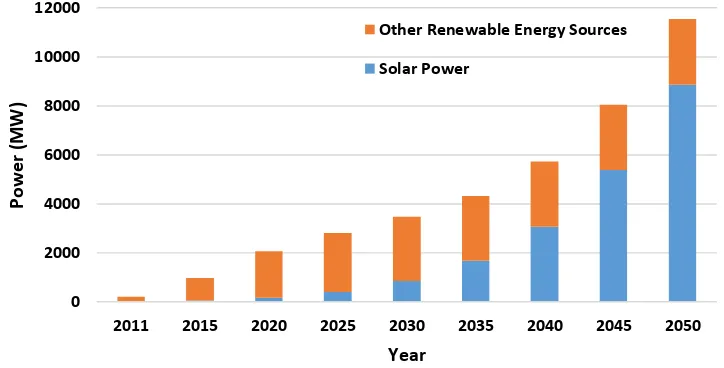
Recently, solar power has been given more attention in Malaysia, which can be seen from the government subsidies and incentives dedicated to encourage PV installation. Malaysian government aimed for a significant step toward enhancing renewable energy in 2011 by issuing Renewable Energy Act 2011 (Tam, 2013). The Sustainable Energy Development Authority Malaysia (SEDA) was established under this Act to promote, stimulate, facilitate and develop sustainable energy. Some recommendations have been introduced such as policies of laws, promoting sustainable energy by introducing Feed-in Tariff law, and carrying out related researches, assessments, and studies. At the end of 2012, the total renewable energy capacity connected to the Malaysia grid was 98.52 MW, in which 25 MW of them was produced by solar power (SEDA Report, 2012). The target for SEDA is a total expected renewable energy (RE) capacity of 2,065 MW by 2020, in which 175 MW of it will be produced by solar power. The expected targets of Renewable Energy development in Malaysia by 2050 are shown in Figure 1.1 (SEDA Action Plan, 2008).
3
energy and the system’s technical lifetime. Inaccurate design of solar plant may negatively affect the output power of the plant and pose danger to the solar plant equipment.
Figure 1.1 : The Expected Target of Renewable Energy Development by 2050 The PV applications can be divided generally into two categories; off-grid applications and grid-connected. Off-grid PV system is a system that is not connected with the utility grid, and it is considered a stand-alone system. This system normally contains storage unit to supply energy when needed, and it is used in small-scale applications.
Grid-connected PV system is a system that is connected to the utility power grid, and it supplies the power directly into the grid, so any onsite load is fed by combination of power generated by the PV system and the utility power grid. Grid-connected system does not require storage unit because no extra power after feeding the public grid (Kumi, & Hammond, 2013). The produced energy from the solar power system can be sold to the main grid under economic system which is normally called Feed-in Tariff. In this research, grid-connected system has been evaluated and verified of its possibility of achieving its target.
This dissertation presents evaluation and analysis on a 2 MW solar PV plant located in Melaka. Two types of PV module technology were considered, namely poly-crystalline and thin film modules. The study was conducted considering that the location of the plant (Melaka) has coordinates of 2.3o North latitude, 102.3o East longitude, and at altitude around
0
2011 2015 2020 2025 2030 2035 2040 2045 2050