Analytical Studies of the Excitation System of Synchronous
Generator in Steam Power Plant Unit 3 and 4 at PJB UP Gresik
Rizky Catur Pamungkas
1, Muhamad Yusvin Mustar
2, Ramadoni Syahputra*
31,2,3Department of Electrical Engineering, University of Muhammadiyah Yogyakarta
Jl Lingkar Selatan Tamantirto Kasihan Bantul, (0274) 387656 *Corresponding author, e-mail: [email protected]
Abstract–Generator or alternator is a device that has a function to convert or transform mechanic energy to electricity. Electricity conversion need process with giving strengthening with excitation current to coil magnetic field that placed on sync generator. Excitation current that flows on magnetic field coil will cause magnetic flux. Generator sync on PLTU unit 3 and 4 PJB UP Gresik use excitation system with excitation static type, this type of excitation it uses carbon brush as a media to conduct excitation current, this excitation system use the output of sync generator. In reality this excitation current which exist on PLTU unit 3 and 4 have to should always be taken care so the system can operate normally and commonly the fault that happened is under excitation and over excitation so it can be prevent. Step taken to avoid damaging the generator sync that caused by excitation current, steps that have to be taken are understanding the characteristic of system excitation setting, anchor current, voltage generator, and loading. The value of loading is very affecting the value of excitation current that injected to generator, the purpose of this process of excitation current injection is to maintain the stability from sync generator voltage so that the condition is staying on its normal condition. Copyright © 2017 Universitas Muhammadiyah Yogyakarta- All rights reserved.
Keywords : Sync Generator, Excitation Current, Excitation System, Over Excitation, Under Excitation.
I.
Introduction
Generator or also called an alternator is an electric machine that serves as a tool to generate electrical energy by converting mechanical energy into electrical energy. The magnetic field coil on the synchronous generator rotor is given an excitation current (excitation) to generate GGL induction. Excitation of the synchronous generator is a direct current in the field windings that exist on the rotor, with the exisiting of the current it will generate magnetic flux.
Disturbances that often occur in the generator include disturbances in the stator, disruption in the rotor (excitation system), and back up the existing installation outside the generator. One of the most common disturbances of generators is the disturbance of the amplifier system or excitation system, which can be fatal to the
generator causing the generator to trip and disrupting the supply of electricity to the consumer. Based on the problems mentioned above, the authors are interested to examine the excitation system and synchronous generator characteristics that exist in PLTU units 3 and 4 in PT PJB UP Gresik. By knowing the excitation system and its characteristics, it is possible to avoid damage to the generator resulting from excessive excitation or deficiency.
II.
Basic Theory
2.1 Definition Of Generator
Copyright © 2017 Universitas Muhammadiyah Yogyakarta - All rights reserved Journal of Electrical Technology UMY, Vol. 1, No. 3
useful form of energy. Synchronous generator is an electric machine that has a function to generate electrical energy by converting mechanical energy into electrical energy (Armansyah, 2016). The generator works by faraday law which in large measure states the magnitude of the induced electrical force will be directly proportional to the rate of change of the sum of the line of force through the coil.
Fig. 1. GGL induced per coil winding
The rotation speed of the rotor with the rotating magnetic poles has the same speed as the stator rotary field, it becomes the source of the sync speed at the generator itself. The generator rotor consists of the field winding supplied by direct current and will produce a magnetic field having the same rotational speed and direction as the rotation of the rotor. The relation between the machine magnetic field and the generator's electric frequency can be explained in the equation as follows :
...(2.1)
Explanation : f = Electrical frequency (Hz)
n = Rotary speed or rotation of magnetic field (rpm)
p = Number Of Poles
2.2 Excitation on Synchorous Generator System Excitation system is a amplifying system
contained in the generator, by providing a current amplifier at the generator field coil that arise because of the magnetic field caused by a direct current.
Excitation current is a current which is given to the magnetic poles, with a large set smaller than the value of the excitation current, it can obtain the value of the desired generator output voltage and reactive power (Basofi, 2014).
Excitation system itself is divided into two types of excitation systems with brush and without
brushes (brushless excitation).
1. Excitation system with brush
Excitation system with brush This itself is divided into 2 types of excitation system dynamic and static excitation systems.
a. Dynamic excitation system
Dynamic excitation system is a excitation current which this excitation system supplied by the exciter machine (engine driver). In this excitation system can use a DC generator or an AC generator but first rectified by rectifier
because the current used in the excitation system is a direct current. The flow will be channeled to the slipring then channeled to the second generator amplifier field.
Fig. 2. Excitation System Dynamic
b. Static excitation system
The static excitation system also is described as a self-excitation because this excitation system is supplied from the synchronous generator itself but needs to be rectified by the rectifier first. On the rotor there is little left and the magnetic field will induce a voltage in the stator. the voltage will then be put back into the rotor which previously had been rectified by the rectifier,
Fig. 3. Static Excitation System
2. Excitation system without brush
This excitation system prioritizes the performance of pilotexciter and a system that will deliver on the main generator excitation current. pilot exciter consists of an alternating current generator that hasa three-phase stator coil and a magnetic field that is attached to the rotor shaft. The following diagram on the working principle of the excitation system without brush:
Fig 4. Excitation system without brush
2.3Effect of Exicitation Setting on Generator Excitation Settings Sync The excitation system be changed it will affect the value of the magnetic flux ( ö) along with the rise in the value of the excitation current. This is made clear in the following equation:
Regulated excitation current in the generator working in parallel where the condition of rotation ( n) fixed the value of the magnetic flux will go up as well as reactive power needed will also increase, but the value of active power will
not be changed so as to affect the value of the power factor.
Generators that work in parallel (G1 and G2) will supply each half load of reactive power, so each generator will supply a current of value I so current that must be supplied to the generator system to work in parallel yng is worth 2I.
In the generator working in parallel and a strengthening of the generator is increased (eg G1), there will be a rise in the value of the induced voltage generator 1 (E1) which makes E1> E2 this will result in the circulation currents (I s).
III.
Research Methodology
In this research there are several steps work done to achieve the desired end result according to the flow diagram as can be seen in Fig. 3.1.
Thesis Research Flow Diagram
START
PRELIMINARY STUDIES
FORMULATION AND IDENTIFICATION OF PROBLEMS
STUDY OF LITERATURE AND THEORETICAL BASIS
OBSERVATION OF SYNC GENERATOR SYSTEMS ON
LOCATION
DATA COLLECTION
PROCESSING AND ANALYSIS OF DATA
RESULT
CONCLUSION
END
Fig. 5. Flow diagram of the research
3.1 Preliminary studies
Copyright © 2017 Universitas Muhammadiyah Yogyakarta - All rights reserved Journal of Electrical Technology UMY, Vol. 1, No. 3 3.2 Formulation and Identification of Problems.
After conducting the preliminary studies carried out identifying the existing problems on location research.Then cause from the problem can be followed by observation directly or withstages Interview. In this research raised issues regarding the existing excitation system in the power plant units 3 and 4 at PT PJB UP Gresik.
3.3 Basic Theory of Library Studies.
The next step is doing library research and the basic theory is to find the reference (information) that can be used as a base or as a parameter in resolving the issues raised in the thesis. This literature study can be sourced from journals, books, and other sources.
3.4 Evaluation Observations Sync Generator Systems in Work location.
This observation aims to determine the parameters of what will be used in resolving the issues raised in the final work. This observation is also to understand the system and the process of excitation of the power plant units 3 and 4 at PT PJB UP Gresik.
3.5 Data collection.
The data that need required to support the completion of this thesis. The data collection can be done by direct observation data needed in the power plant units 3 and 4 at PT PJB UP Gresik. Data collection can also be done by means of interviews with the various parties concerned with the topics raised in this thesis
3.6 Data processing.
Data processing is performed after all the data needed for the study was complete. case that do is grouping the data, in this research data are grouped in the form of excitation current, excitation voltage, power factor, and loading the synchronous generator in the power plant units 3 and 4.
3.7 Analysis.
Once the data has been processed then do follow-up may be charting the relationship existing parameters with the conditions of a synchronous generator in the power plant units 3 and 4. From the graph of these parameters it can be concluded and the anticipation that may be taken if there is a
problem related to this thesis that occurred in the power plant generation systems uni 3 and 4 at PT PJB UP Gresik.
3.8 Result and Conclusions.
After analyzing the existing data or graph then conclude the thesis. After finished the thesis we expected this thesis can become a reference in the event of disruption or problems in the field related to the topic of discussion.
IV. Results and Discussion
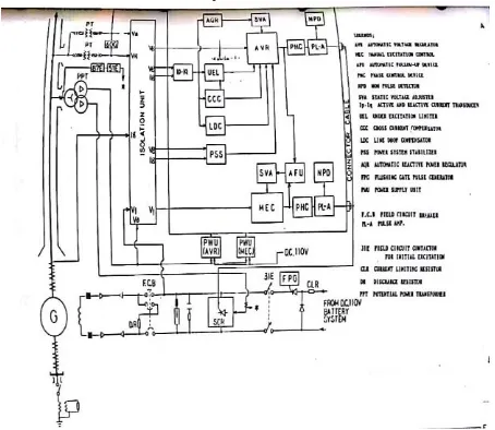
4.1 Working Principle Excitation System Power Plant Units 3 and 4 PJB UP Gresik.
Excitation systems at power plant units 3 and 4 do not require the generator additional source excitation synchronous generator, but take advantage of it's own generator output as the excitation source but first needs to be rectified using the thyristor. Excitation system is also called as self-excitation or more commonly known as a static excitation system
Fig. 6. Excitation System Sync Generator PLTU Unit 3 and 4 di PT PJB UP Gresik
sourced from the battery to the rotor by activating the FCB ( field circuit breaker) which exists. With current injection that comes from the battery, the generato sync will begin generates a voltage terminal. This process will continue until the value of the synchronous generator voltage reaches 15% of the nominal voltage of the synchronous generator. When this condition is reached, the
thyristor will be active and raise the value of the synchronous generator terminal voltage up to 15 KV.
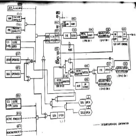
When the condition of excitation current has reached a value of 40% of the excitation current at no load, the contactor 31e which becomes a liaison between the generator rotor with the battery will open, on the condition excitation system will begin to be supplied by the output of the synchronous generator sindiri, but first output of the synchronous generator will be rectified and lowered in advance by the thyristorrectifier.
Fig 7. Excitation System Process In PLTU Units 3 and 4 in PT PJB UP Gresik
The value which is the terminal voltage generator output power plant units 3 and 4 are at 15 KV 3 phase voltage output terminal of the synchronous generator is first necessary impaired to use transformers step-down to obtain the
excitation voltage of 790 VAC 3 phase.
The output voltage of the transformer step-down
This excitation with a value of 790 VAC 3 phase will then be rectified and lowered again its value to produce a DC voltage with a value of 110 VDC.
4.2 Analysis of Characteristic of Synchronous Generation Excitation System at PLTU Units 3 and 4 in PT PJB UP Gresik
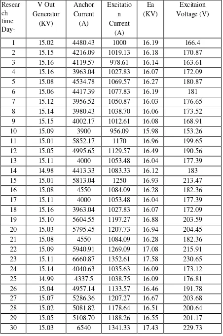
At Table I, the value of Vout generator, frequency, active power, reactive power, current anchors, excitation current, excitation voltage and power factor is the average value per hour in one day.
Copyright © 2017 Universitas Muhammadiyah Yogyakarta - All rights reserved Journal of Electrical Technology UMY, Vol. 1, No. 3 4.3 Analysis of the Relation of Current Excitation
Against the Current of anchors
Fig. 7 shows the relation between the excitation current to the current anchor that of the power plant units 3 and 4, on the graph shows that the value of the excitation current (If) is proportional to the value of the current anchor (Ia) which is in a synchronous generator, in other words that the greater the value of the excitation current is injected it will make the value of the current anchor on a synchronous generator will be the anchor. Great current change according to the large value of the excitation current is injected to the rotor coil contained in the synchronous generator power plant units 3 and 4.
Fig. 7. Graph of Excitation Current Relation with Anchor Current in Synchronous Generator PLTU
Units 3 and 4
4.4. Analysis of Effect of Voltage Fluctuation on
Sync Generation
Synchronous generator Based on the specifications of the generator as well as the daily operations of data power plant units 3 and 4 in the table daily operations, the value of Ea to the
The above data can be used in determining the value Zbase (impedance) using the following
equation:
...(4.1)
From the data and calculations above, the value of Ea as follows:
formula can be seen from the following table: Table II shows the Value of Calculation Results GGL Induction on Synchronous Generator Power Plant Units 3 and 4 PJB UP Gresik
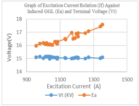
From the table on the above calculation can be made a graph showing the relationship between the excitation current is injected to the terminal and the EMF induced voltage (Ea). The following chart:
Fig. 8. Graph of Relation between Excitation Current (If) with Induced GGL (Ea) and Terminal
Voltage (Vt) in Synchronous Generator PLTU Units 3 and 4
Regarding the effect of the excitation current (If) of the induction GGL (Ea) and the terminal voltage (Vt) to the synchronous generator power plant unit 3 and 4 in PJB UP Gresik. The graph shows that the greater the value of the excitation current injected into the synchronous generator will make the value of EMF induction that there are likely to increase. It was determined that the increase of the terminal voltage (Vt) to the synchronous generator caused by the increasing value of the excitation current (If) which is injected, it aims to maintain the stability of terminal voltage (Vt) generator synchronous, so the terminal voltage that is initially low due to a change or an increase in the load, then it can be stabilized again by increasing the excitation current is injected to strengthen the current strengthening of the existing terrain at a synchronous generator.
4.5 Relation of Load and Excitation Current
Figure 9 shows that the greater the value of the load that is in the power plant units 3 and 4 PJB UP Gresik then the value of the excitation current (If) were injected at a synchronous generator that is also increased, it aims to maintain the stability of the terminal voltage of the generator synchronous power plant units 3 and 4 of the. The principle is that when the value of loading up it will result in the value of the network voltage decreases, it makes the value of the terminal voltage will also decrease. So to overcome this, the need to increase the value of the excitation current injected into the synchronous generator.
Fig. 9. Graph of Load Relation with Excitation Current on Synchronous Generator PLTU
Units 3 and 4
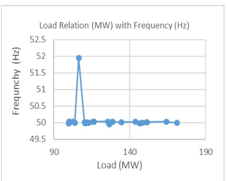
Power plant units 3 and 4 at PJB UP Gresik also preserve the value of the frequency synchronous generator that remains constant is in the range of 50 Hz. It can be seen from the graph as follows:
Copyright © 2017 Universitas Muhammadiyah Yogyakarta - All rights reserved Journal of Electrical Technology UMY, Vol. 1, No. 3
Fig. 10. Graph of Relation to Excitation Flow on PLTU Units 3 and 4 PJB UP Gresik
In the graphs above show the fluctuation condition, it could be due when the system has been synchronized with the network's existing system will serve the needs of loading.
By knowing the characteristics of this synchronous generator excitation system, damage to the generator, which is caused by under excitation or over-excitation can be avoided.
V.
Conclusion
Excitation system used in the power plant units 3 and 4 in PJB UP Gresik is a static excitation systems. System of static excitation is an excitation system that utilizes the output voltage of the synchronous generator itself to get excitation current. Excitation current (If) affect the value of the current anchor (Ia) which is in a synchronous generator in the power plant units 3 and 4. The effect in question is the value of the excitation currents (If) is proportional to the current value of the anchor (Ia). Analysis performed explains that value excitation current (If) affect the value of the output voltage fluctuation in the synchronous generator in the power plant units 3 and 4, that the value of the excitation current (If) is proportional to the induced emf (Ea) and the generator output voltage (Vt).
Imposition of that of the power plant units 3 and 4 in PJB UP Gresik changing, it is tailored to the needs of the network and consumers. Changes in the terminal voltage (Vt) generator sync in the power plant units 3 and 4 at PJB UP Gresik is constant, which is in the range of 14.98 to 15:16
KV of the existing nominal voltage of 15 kV. The condition of the excitation system in the power plant units 3 and 4 PJB UP Gresik can be said to be in good shape. This is because the existing excitation system managed to maintain the stability of the terminal voltage synchronous generator that is stable in the range of 15 KV.
References
[1]. Bandri, Sepannur. 2013. Analisa Pengaruh Perubahan Beban Terhadap Karakteristik Generator Sinkron. Padang: Institut Teknologi Padang.
[2]. Basofi, Syamsul Amien. 2014. Studi Pengaruh Arus Eksitasi Pada Generator Sinkron Yang Bekerja Paralel Terhadap Perubahan Faktor Daya. Medan: Universitas Sumatera Utara.
[3]. D. Jolevski. 2009. Excitation System of Synchronous Generator. Split: University of Split. [4]. Jerkovic, dkk. 2010. Excitation System Models Of
Synchronous Generator. Osijek: University of Osijek
[5]. Kurniawan, Aditia. 2015. Analisa Pengaruh Arus Eksitasi Generator Terhadap Pembebanan Pada PLTA Cirata Unit 2. Bandung: Politeknik Negeri Bandung.
[6]. Priyadi, Irnanda. 2014. Terhadap Efek Harmonisa Pada Hubungan Belitan Generator Sinkron Dengan Beban LHE. Bengkulu: Universitas Bengkulu.
[7]. Ridzki, Imron. 2013. Analisis Pengaruh Perubahan Eksitasi Terhadap Daya Reaktif Generator. Malang: Politeknik Negeri Malang [8]. Septian, Dwi. 2016. Studi Sistem Eksitasi Pada
Generator Sinkron Di Pembangkit Listrik Tenaga Air (PLTA) Musi Bengkulu. Yogyakarta: Universitas Muhammadiyah Yogyakarta
[9]. Sunarlik, Wahyu. 2013. Prinsip Kerja Generator Sinkron. Diunduh pada tanggal 15 November 2017. Pukul 20.40 WIB., dari
http://updkediri.ac.id/wp- content/uploads/2014/06/Prinsip-Kerja-Geneator-Sinkron.pdf.
[10].Syahputra, R. 2012. Distributed Generation: State of the Arts dalam Penyediaan Energi Listrik. Yogyakarta: LP3M UMY.
[11].Syahputra, R. 2016. Transmisi dan Distribusi Tenaga Listrik. Yogyakarta: LP3M UMY.
[12].Syahputra, R. 2015. Teknologi dan Aplikasi Elektromagnetik. Yogyakarta: LP3M UMY. [13].Terimanda, Nasrun Hariyanto, Syahrial. 2016.
[14].Tiantoro, Feliks. 2009. Analisis Sistem Eksitasi Pada Generator Sinkron Tiga Fasa 67 MVA Di PT Indonesia Power PLTA Panglima Besar Soediran Unit Bisnis Pembangkit Mica Banjarnegara. Purwokerto: Universitas Jendral Soedirman. [15].Syahputra, R., Robandi, I., Ashari, M. (2015).
Reconfiguration of Distribution Network with DER Integration Using PSO Algorithm. TELKOMNIKA, 13(3). pp. 759-766.
[16].Syahputra, R., Soesanti, I. (2016). Design of Automatic Electric Batik Stove for Batik Industry. Journal of Theoretical and Applied Information Technology (JATIT), 87(1), pp. 167-175.
[17].Syahputra, R., Robandi, I., Ashari, M. (2014). “Optimal Distribution Network Reconfiguration with Penetration of Distributed Energy Resources”, Proceeding of 2014 1st International Conference on Information Technology, Computer, and Electrical Engineering (ICITACEE) 2014, UNDIP Semarang, pp. 388 - 393.
[18].Soedibyo, Ashari, M., Syahputra, R. (2014). “Power loss reduction strategy of distribution network with distributed generator integration”, Proceeding of 2014 1st International Conference on Information Technology, Computer, and Electrical Engineering (ICITACEE) 2014, UNDIP Semarang, pp. 404 - 408.
Authors’ information
Rizky Catur Pamungkas Received B.Sc degree from Department of Electrical Engineering Universitas Muhammadiyah Yogyakarta, Yogyakarta, Indonesia in 2018. His research interests are in computational of power system and artificial neural network in power system
Muhamad Yusvin Mustar Received Diploma degree Electrical Engineer from Universitas Haluoleo, Kendari in 2009, B.Sc. degree from Department of Electrical Engineering Universitas Muhammadiyah Yogyakarta in 2011, M.Eng. degree from Department of Electrical Engineering and Informatics Technology, Universitas Gadjah Mada, Yogyakarta, Indonesia in 2014. Muhamad Yusvin Mustar, M.Eng. is a Lecturer in Department of Electrical Engineering, Faculty of Engineering, Universitas Muhammadiyah Yogyakarta, Indonesia. His research interests are in human-robot interaction, human-machine interaction, robotics, electrical and electronics engineering.
Ramadoni Syahputra received B.Sc. degree from Institut Teknologi Medan in 1998, M.Eng. degree from Department of Electrical Engineering, Universitas Gadjah Mada, Yogyakarta, Indonesia in 2002, and Ph.D degree at the Department of Electrical Engineering, Faculty of Industrial Technology, Institut Teknologi Sepuluh Nopember, Surabaya, Indonesia in 2015.