MODELLING AND SIMULATION OF CYLINDER DEACTIVATION SYSTEM APPLIED TO PASSENGER VEHICLES
AIZUDDIN FAHMI BIN MOHD RIDUAN
SUPERVISOR DECLARATION
“I hereby declare that I have read this thesis and in my opinion this thesis is sufficient in terms of scope and quality for the award of the degree of
Bachelor of Mechanical Engineering (Automotive)”
MODELLING AND SIMULATION OF CYLINDER DEACTIVATION SYSTEM APPLIED TO PASSENGER VEHICLES
AIZUDDIN FAHMI BIN MOHD RIDUAN
This thesis is submitted as to fulfil the requirements for the award of the degree of Bachelor of Mechanical Engineering (Automotive)
Faculty of Mechanical Engineering Universiti Teknikal Malaysia Melaka
AUTHOR DECLARATION
“I hereby declare that the work in this thesis is my own except for summaries and
quotations which have been duly acknowledged.”
Signature: _______________________________
Author: AIZUDDIN FAHMI BIN MOHD RIDUAN
Dedicated to
ACKNOWLEDGEMENT
The writer expresses his highest gratitude to the supervisor of this project, Dr.
Ahmad Kamal bin Mat Yamin for his contributions and support throughout the
research was carried out. Without him, the project cannot be done any better and
smoother.
Recognition is also given to other lecturers who help the writer along the way
during the methodology process which helped the writer achieved the simulation
results for this research.
Finally, the writer wants to express his deepest sincere appreciation to all his
colleagues that assisted him not only with the research but also other side projects
ABSTRACT
Cylinder Deactivation System, CDS or generally referred to as variable
displacement is a technology developed that can permit the total engine displacement
to vary by shutting down one or more cylinders to increase overall fuel efficiency.
The primary study of this research was to simulate how CDS would perform when
applied to passenger vehicles by using MATLAB Simulink. Vehicle modelling using
MATLAB Simulink is a process of creating a reference tool to the real world
counterpart and using existing parameters to obtain results via simulation. The
difficulty in this case study was formulating a functioning model for simulation
purposes and determining the CDS performance under any number of working
cylinders. Objectives of the research were formulating the vehicle longitudinal
model, predicting CDS performance when applied to passenger vehicles, and
proposing a control strategy for the CDS when used. The methods used were first
deriving the necessary equations based on vehicle dynamics, creating the vehicle
longitudinal model using the developed equations, and finally simulate it to get the
theoretical results. The results gathered from this research were based on the output
CONTENTS
CHAPTER TITLE PAGES
AUTHOR DECLARATION ii
DEDICATION iii
ACKNOWLEDGMENT iv
ABSTRACT v
CONTENTS vi
LIST OF TABLES ix
LIST OF FIGURES x
LIST OF SYMBOLS xi
CHAPTER 1 INTRODUCTION 1
1.0 Introduction 1
1.1 Problem statement 4
1.2 Objectives 4
1.3 Scope of study 5
CHAPTER 2 LITERATURE REVIEW 6
2.0 Introduction 6
2.1 Fuel-efficient assist system relating to speed 6
2.1.1 Variable displacement 7
2.1.2 Variable valve timing 8
2.1.3 Start-stop system 10
2.1.4 Driving mode change 11
2.1.4.1 ECO mode 12
2.1.4.2 Normal mode 13
CHAPTER TITLE PAGES
2.1.4.4 EV mode 14
2.1.5 Active spoiler 14
2.2 Previous work of CDS 15
2.3 Vehicle speed as reference 16
CHAPTER 3 METHODOLOGY 17
3.0 Introduction 17
3.1 Derivation of equations for modelling 17
3.1.1 Equations of motion 17
3.1.1.1 Vehicle load distribution 18
3.1.1.2 Drag forces 19
3.1.1.3 Tyre/road tractive properties 20
3.1.1.4 Wheel dynamic equations 22
3.1.2 Powertrain model 23
3.1.2.1 Engine torque curve 24
3.1.2.2 Engine dynamics 25
3.1.2.3 Gearbox model 25
3.1.3 Brake system model 26
3.1.3.1 Servo actuated brake system 27
3.1.3.2 Brake friction characteristic 27
CHAPTER 4 RESULTS AND DICUSSION 29
4.0 Simulation of the vehicle longitudinal model 29
4.1 Vehicle longitudinal model engine parameters 30
4.2 Result and discussion from the simulation 31
4.2.1 Vehicle speed with all cylinders running 31
4.2.2 Vehicle speed with CDS 33
4.2.2.1 Vehicle speed (3 cylinders) 33
4.2.2.2 Vehicle speed (2 cylinders) 34
4.2.2.3 Vehicle speed (1 cylinder) 35
4.2.2.4 Vehicle speed comparisons 36
CHAPTER TITLE PAGES
CHAPTER 5 CONCLUSION 38
5.0 Conclusion 38
5.1 Recommendation for project continuation 39
REFERENCES 40
LIST OF TABLES
NO TITLE PAGES
1.1 EEV requirements for road vehicles 2
1.2 EEV requirements for two wheelers 3
3.1 Pacejka Magic Tyre Model coefficients 22
LIST OF FIGURES
NO TITLE PAGES
1.1 Volkswagen engine with ACT 2
2.1 Bentley V8 engine with variable displacement 7
2.2 General VVT system configuration 9
2.3 Mercedes Benz start-stop system button 10
2.4 Prius Gen 3 mode buttons placement 12
2.5 Pagani Huayra active spoiler and Formula 1 DRS 15
2.6 Perodua Caliphs and manually operated CDS 15
3.1 Tyre friction against slip ratio graph 21
3.2 Throttle setting against wheel speed 26
4.1 Basic layout of the vehicle longitudinal model 29
4.2 Vehicle speed vs time graph 31
4.3 Brake torque 32
4.4 Vehicle speed vs time with 3 working cylinders 33
4.5 Vehicle speed vs time with 2 working cylinders 34
4.6 Vehicle speed vs time with 1 working cylinder 35
LIST OF SYMBOLS
ܨ = Force acting on the vehicle
ߤ = Pacejka ‘magic’ model constant
ܨ = Normal force
ܨ = Total force acting on the vehicle
ܸሶ = Rate of velocity
g = Gravitational acceleration
m = Mass of vehicle
ܨௗ = Drag force
L = Wheelbase
B = Length from rear axle to center of gravity
C = Length from front axle to center of gravity
H = Height of center of gravity
ܨ = Aerodynamic force
ܨ = Resistance force
ܥ = Rolling resistance coefficient
A = Frontal area of the vehicle
Cd = Aerodynamic drag coefficient
ߩ = Density of air
ߣ = Slip ratio
߱ሶప = Wheel dynamic
߬ = Engine torque delivered to each wheel
߬ = Brake torque applied to each wheel
߬ = Reaction torque on each wheel due to the tyre tractive force
߬ௗ(ఠ) = Viscous friction torque
߱ = Wheel speed
CHAPTER 1
INTRODUCTION
1.0 INTRODUCTION
Modern vehicle nowadays strive to achieve EEV status which abbreviates
from Energy Efficient Vehicle. EEV is defined as vehicles that meet a set of define
specification in terms of carbon emission level (g/km) and fuel consumption
(l/100km) (source from Malaysian Automotive Institute, MAI). One strategy to reach
the EEV requirement is by employing a fuel-efficient assist system. A lot of systems
had been used in today’s cars such as variable valve timing (VVT), cylinder
deactivation system (CDS), active spoiler, start-stop and many more. In this research,
most of the work will be based on the cylinder deactivation system since it is the
most common fuel-efficient assist system applied to passenger vehicles.
Cylinder deactivation system, CDS or also commonly known by variable
displacement is a technology developed that can allow the overall displacement
engine to change by deactivating one or more cylinders to increase the overall fuel
efficiency. This system is widely used in multi-cylinder internal combustion engines.
Even though this application has been seen only recently, the technology was around
for quite some time. The first being is the hit-and-miss engine where it was
developed in the late 19th century. It was a single cylinder stationary cylinder which
had a centrifugal governor that cuts the cylinder out of the operation as long as the
engine speed was operating above a set limit usually by holding the exhaust valve
open. Current technology of CDS however uses the same principle but cuts off any
Due to the cause of decreasing the fuel consumption, it is important that CDS
needs to be research much more prominently. Prior to this, CDS has only been used
in vehicles with big engines such as V6’s and V8’s. However, the system now seems
to be adapted into smaller engine such as the in-line 4-cylinder engines. This is
because car manufacturers are opted for engine downsizing of engine to reduce
carbon emissions, increasing fuel efficiency and also cut cost. The study about CDS
is significant because this system has recurrent problem which is pumping losses
when the cylinders in an engine are partially off.
[image:16.595.122.518.254.443.2]
Figure 1.1 Volkswagen engine with Active Variable Displacement (ACT)
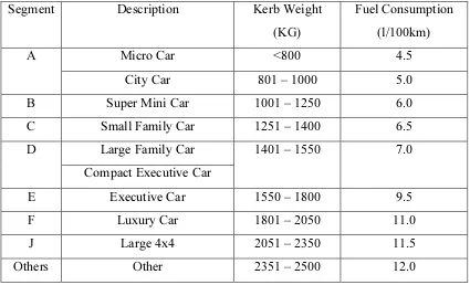
Table 1.1 EEV requirements for road vehicles
Segment Description Kerb Weight
(KG)
Fuel Consumption
(l/100km)
A Micro Car <800 4.5
City Car 801 – 1000 5.0
B Super Mini Car 1001 – 1250 6.0
C Small Family Car 1251 – 1400 6.5
D Large Family Car 1401 – 1550 7.0
Compact Executive Car
E Executive Car 1550 – 1800 9.5
F Luxury Car 1801 – 2050 11.0
J Large 4x4 2051 – 2350 11.5
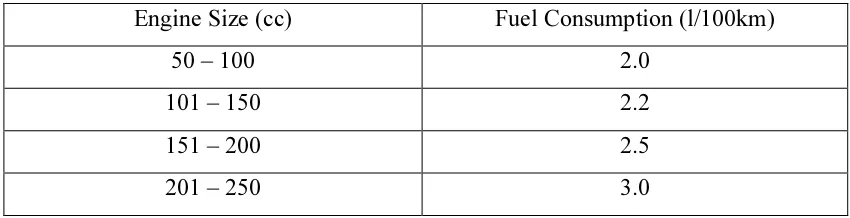
[image:16.595.107.532.508.766.2]Table 1.2 EEV requirements for two wheelers
Engine Size (cc) Fuel Consumption (l/100km)
50 – 100 2.0
101 – 150 2.2
151 – 200 2.5
201 – 250 3.0
Pumping losses has always been a major concern in CDS. This inefficiency
occurs during light-load or part-load driving conditions where only a portion of the
engine’s total power is used. Throughout part-load driving, the throttle valve is
nearly closed and this causes the engine to draw air into the cylinders with extra
work hence inadvertently making pumping loss happens. One way overcome this is
by decreasing the compression ratio which in return also reduces the pumping loss
during part load. Another solution to counter this is by induce more air into the
cylinders during light-load conditions
To decrease the compression ratio, we can take inspiration from the Atkinson
Cycle which is commonly used in hybrid vehicles. The Atkinson Cycle consist of 5
strokes process which are intake, first compression, second compression, power and
exhaust in a flowing order. What differentiates the Atkinson Cycle and the widely
used Otto Cycle in automobiles is that during the first compression, the intake valve
is kept open till the second compression stroke so that the air can be pushed out back
into the intake manifold. This causes the compression ratio to decrease and also flow
the air back into the other cylinders which needs more air thus decreases the
pumping loss. Other ways to draw more air into the cylinder is by having a
turbocharger or using a 4-2-1 exhaust manifold which can help engine breathing to
be more efficient. Besides mechanical solutions, employing a control strategy into
the engine process can also help improve the overall efficiency by controlling the
valve timing or number of cylinder usage during part-load conditions.
Some of the solutions stated to counter the pumping loss have been applied in
modern vehicles of today. The Atkinson Cycle as said is commonly used in hybrid
vehicles because the electric motor can compensate the side effects when
compression ratio is decrease. Even though pumping loss can be reduce when the
compression ratio is decrease, the negative effect to that is producing less power
performance, the side effect can be countered. Turbocharging can be seen more and
more in passenger vehicles nowadays due to output power it can produced even in
small capacity engines. The prime example of this can be seen in Volkswagen
engines with variable displacement technology where the turbo can help draw more
air into the working cylinders.
1.1 PROBLEM STATEMENT
Cylinder Deactivation System, CDS currently is being adapted more
regularly into smaller engines unlike before. This is to help increase the engine’s
maximum efficiency during part-load driving. Hence, the research challenge is on
how to formulate a math model to generate a control strategy so that the number or
functional cylinders during part or full load can be determined.
1.2 OBJECTIVES
1. To develop a vehicle longitudinal model.
2. To predict the performance of the cylinder deactivation system when applied
to passenger vehicles.
3. To propose a control strategy when the cylinder deactivation system is used.
The aim of this research is to model and simulate the cylinder deactivation
system when applied to passenger vehicles. The first objective is done so that a clear
output data which is the vehicle speed can be generated from the model to predict the
performance of CDS. The second objective is executed to determine how the
cylinder deactivation system can affect the car performance by applying it to the
vehicle longitudinal model. The third and final objective is done to find out the
number of functioning cylinders required by the engine depending on the load
1.3 SCOPE OF STUDY
1. A compact city car (A-segment) with a kerb weight 801-1000kg will be used
as the test subject for the research.
2. The input data that will be from the driving cycle.
3. A level road surface is one the parameters for the simulation test as the
vehicle model will be drive forwards only with no cornering.
The data of this research is first followed up by the first objective. When the
vehicle longitudinal model is complete, the simulation then can take place to
generate the necessary data. The second outcome would be coming up with a control
strategy. The analysis from the results can help to formulate the control strategy for
the vehicle. The third result would be predicting the performance of the system when
CHAPTER 2
LITERATURE REVIEW
2.0 INTRODUCTION
Cylinder Deactivation System, CDS has prominently evolved throughout the
years in automotive advancement. As stated before, it has been around since the 19th
century. The application of the systems varies depending on how the manufacturers
intend on making it work in an internal combustion engine. However, the most
significant similarities between all of them are that it depends on the speed of the
moving vehicle. Hence, it is important to study existing similar CDS counterparts as
well any other fuel-efficient assist system that have been applied to modern vehicles
so that the modelling of vehicle longitudinal model can take place.
2.1 FUEL-EFFICIENT ASSIST SYSTEM RELATING TO SPEED
In this section of the report, information regarding fuel-efficient assist system
applied to passenger vehicles will be explained. It is noted that the examples shown
are systems that functions based on the vehicle motion speed. Even though the
research will be based on CDS, other examples such as variable valve timing,
start-stop system, driving mode change and active spoiler will be taken into consideration
to help guide the modelling of the vehicle longitudinal model for simulation
2.1.1 Variable displacement
Variable displacement can be considered the main example for cylinder
deactivation system due to its working mechanism. It operates by changing the
engine output capacity which is done usually by switching off one or more cylinders
which in return change the total displacement of an engine to give out better fuel
efficiency.[1] This system is widely used in vehicle which has multi-cylinder engines.
Car manufacturers have been applying this technology since 2005 but the idea have
been long existed prior before that.
During low-load conditions, the system is applied so that it can increase the
fuel efficiency and also reduced the gas emission in the process. Normally, the driver
only uses one third of an engine’s total power output in this kind of situations.
During which, the throttle valve is nearly shut. However, the engines still requires
some work to draw in air into the engine. Due to this, pumping loss will occur.
There are even in some cases where a car with higher capacity engine needs
to pull in a lot of air at light load conditions which can cause the pressure in the
cylinder at top dead center (TDC) to be roughly half that of a typical common
[image:21.595.132.503.465.690.2]smaller in-line engines. Thus, result in lower fuel efficiency.
With variable displacement system functioning at a lower driving load, only
fewer cylinders will be required to draw air into the engine which can help to raise
the air pressure. In absence of this system, fuel is unnecessarily pumped into each
cylinder for combustion process even when no additional power is required during
part-load situations. Therefore, by altering the total engine working cylinders to half,
the amount of fuel consumed in theory can be reduced to half as well. The fuel
consumption figures is said to be decrease to almost 25% when the engine
displacement is cut down during this operation.[3]
The total displacement of an engine can be decreased by shutting down or
deactivating a cylinder with maintaining the intake and exhaust valves of a certain
cylinder to be closed.[2] By doing so, the exhaust gases are unable to escape at the
end of a cycle will be compressed when the piston moves upwards and will be
pushed downwards when it moves downwards. This phenomenon can be called as
the “air spring” effect. The decompression and compression of the trapped exhaust
gases will have an overall effect of where no extra load will be put on the engine.
Latest development concerning variable displacement can be seen from a fuel
cut delivery system where it is also use by the engine management system to turn off
any of the cylinders. The change between full cylinder and deactivated cylinder
operations is also help by improving the ignition and can as well as using an
electronic throttle position. This type of fuel-efficient assist system is usually used in
engines with large capacity displacement which are not designed to be efficient
during low load conditions. For example, a V12 engine can have half of its cylinders
shut off but the disadvantages in that cause the system to have unbalanced cooling
and increase in vibration.
2.1.2 Variable valve timing
Variable valve timing or better known as VVT is a system that can adjust the
engine’s valve lifting timing and it is normally done to increase the performance of
the vehicle while raising the fuel economy and decreasing emissions. This system is
rapidly being used with a combination of variable valve lift systems. Mechanical
devices or electro-hydraulic and camless system are one of the few ways in which
being enforced, many automobile manufacturers prefers the VVT system in their
engines. For a case of a two-stroke engine, a power valve system is used to get the
performance of a VVT system.
In an internal combustion engine, the flow of the intake and exhaust gasses
into and out of the cylinders respectively are controlled with the used of valves. The
lift, timing, and duration of these valves events will have implication on the output
performance of the engine. If an engine does not use variable valve timing, the valve
timing will be equal for all the engine speed and conditions, thus certain
compromises are necessary.[4] An engine that is equipped with this system however
is free from this constraint which allows the performance to become better with the
engine operating range. The valves are usually actuated by camshafts where the cam
lifts the valve open for a certain period of time throughout intake and exhaust stroke.
The timing of the valves for opening and closing is also essential as the camshaft is
[image:23.595.116.529.381.639.2]driven by the crankshaft through chains, gear, or timing belts.
Figure 2.2 General VVT system configuration
The engine when operating at high speeds requires large amount of air to get
the best possible output. However, the intake valves may close before sufficient air
has gone into the cylinder which can results in low output performance. If the
happen when the engine is at lower speeds because it can cause unfinished
combustion to take place and the fuel to exit the engine since the valves are still
open. This in result will induce a reduction in engine performance and also an
increase in emissions.
2.1.3 Start-stop system
A car that has start-stop or stop-start system can automatically shuts down
and restart the internal combustion engine so that the amount of time the engine
spends during idling will be decrease and hence increasing the fuel efficiency as well
as reducing emissions. This technology is very useful for road vehicles in cities or
urban areas where most of the time is spend on queuing at traffic light junctions or
during rush hour where cars constantly come to a halt. This system is predominantly
introduced in hybrid electric vehicles but also has been seen used by car that is
powered by a normal combustion engine. The fuel efficiency is said to be raised from
[image:24.595.116.530.444.673.2]5% to 10% for non-electric vehicles or micro-hybrids.