5 CHAPTER 2 LITERATURE REVIEW
2.1. Literature Review
2.1.1. Previous Research
Ali, Chowdary and Gonzales (2013) aims An Integrated Design Approach for Rapid Product Development journal shown the integrated design approach using reverse engineering (RE), re-engineering (ReE), and rapid development (RpD) system to infuse agile characteristic in the proposed design and development process. It also explain about the integration of RE, ReE and RpD with unconventional approach achieving reduced lead times for design and development of products. Applicate that method to recover the broken clutch shoe design by using Computer Aided Design (CAD) model.
6 2.1.2 Present Research
7
Table 2.1 Comparison Between Previous and Current Research
Author Title Data
Collection Tools Objective Data
Ali, Chowdary and
Gonzales (2013)
An integrated design approach for rapid product
development
Contact CMM Recover broken part
Broken clutch shoe (existing product
without technical drawing)
M. Hussain, CH.
Rao and Prasad
(2008)
Reverse Engineering : Point
Cloud Generation with CMM for Part Modeling and Error
Analysis
Contact
and
non-contact
CMM Design and Error Analysis Injection mould (existing product without technical drawing) Mansor (2002)
Free-Form Surface Models Generation using Reverse engineering Technique –An
Investigation Contact and non-contact 3D scanning, CMM
Investigation Physical object
Lamandau (2015)
Reverse Engineering Approach In Making Emirates Plate (Dia-25cm)
Design At Pt Doulton
Contact CMM Design new product
Emirate Large Plate (Dia-25)cm technical drawing
8 2.2. Gap Analysis
Ali, Chowdary and Gonzales (2013) and M. Hussain, CH. Rao and Prasad (2008)
use reverse engineering to get the design from existing product which are broken
clutch shoe and injection mould. Both are processed without technical drawing
data. M. Hussain, CH. Rao and Prasad (2008) using non-contact scanner and
calculate the error analysis of both scanning process. Mansor (2002) make an
investigation of reverse engineering method which is generated by using
free-form surface generation in model making. Therefore, this research presents
about making a design of Emirate Large Plate (Dia-25cm) with both technical
drawing and existing product using reverse engineering approach.
2.3. Basic Theory 2.3.1. Ceramic
The word ceramic is derived from the Greek keramos, which means “potter’s
clay” or “pottery”. It’s origin is a Sanskrit term meaning “to burn”. (Carter and
Norton, 2013) The early Greeks used the word keramos when describing
products obtained by heating clay-containing materials. The term has long
included all products made from fired clay, including bricks, fireclay re-factories,
sanitary-ware, tableware. (Carter and Norton, 2013).
a. Earthenware
A type of clay that is soft when fired to make pottery and can be scratched
with a knife. It is opaque and has an earthy or granular fracture. Made from
soil that absorb water, fired at low temperature (900°C – 1060°C). Plastically
and tought, but after the firing process it becomes fragile and has so many
pore.
b. Terracotta
A type ofearthenware, is a clay-based unglazed or glazed ceramic where the
fired body is porousIs one of the red soil. ‘Terracotta’ word came from Italian,
means ‘fired soil’. This material can be fired around 1200°C - 1300°C with
adding some chamotte.
c. White Pottery
Is one kind of white pottery, tough, can be fired at high temperature (1250°C).
9
d. Stoneware
Is a though dense, impermeable and hard enough to resist scratching by a
steel point. Can be fired in medium temperature (1150°C) or the earthenware
temperature, also can be fired in high temperature (1250°C). Usually the color
is grey or brownish because of the impurities in the clay used for its
manufacture, and is normally glazed.
e. Porcelain
Porcelain is known as Fine China. The toughness, strength, and
translucency of porcelain arise mainly from the formation ofglass and the
mineral mulita within the fired body at these high temperatures. Usually it is
fired in kiln, temperature between 1250°C - 1440°C. Made from mixing kaolin,
feldspar, silica, and formed by casting technique.
f. Bone China
A type of soft-paste porcelain that is composed of bone ash, felspath
material, and kaolin. It has been defined as ware with a translucent
body containing a minimum of 30% of phosphate derived from animal bone
and calculated calcium phosphate. This mixture is fired around 1200 °C in
two stages. First is a biscuit firing, then glost firing (temperature between
1040°C –1080°C).
g. Raku
It is a traditional type of Japanese Pottery. It is traditionally characterized by
being hand shaped rather than thrown; fairly porous vessels, which result
from low firing temperatures; lead glazes; and the removal of pieces from
the kiln while still glowing hot. The average temperature usually is between
750°C–1000°C.
The material that is usually used in forming process, plastic and non-plastic.
(Arkbuckle. 2014)
1. Various of Clay
a. Kaolin
Kaolin is clay contains kaolinit minerals as the biggest former. The
characteristics of this clay are coarse grained and fragile. It is used for:
1. White earthenware
10
3. Email mixture. Email is a mixture of ceramic and metal. It is used for
making a pot or another household.
b. Ball Clay
This is the most plastic clay for ceramic. It is called ball clay because at
the beginning this clay was sold in ball shaped. The characteristics of this
clay are fine-grained, plastic, and containing carbon.
Usually this is used for white ceramic and email to obtain plastis traits that
facilitate the formation, giving strength to the unfired goods that are not
easily fragile.
c. Stoneware Clay
This material includes pottery because pottery goods at absorbing water,
whereas the porcelain is solid. It includes soil sediments. On earth are
found many kinds of stoneware containing feldspar incorporated in clay.
The characteristics of this material are plastic, good drying, and the raw
color is gray. Usually this material is widely used because it is resistant to
acids and in the manufacturing of ceramic art, tiles and pipes.
d. Earthenware clay
Commonly is used in the manufacturing of bricks, crockeru, pots, and
various other potteries. The characteristics are colored yellow or orange
or red or brown after firing process, depending on the temperature, the
raw color is gray.
e. Fire Clay
Including secondary soil type, as commonly found in the area of coal
seam. It is highly resistant to high temperature, plastic, and coarse
texture. The flame-retardant properties is not contain iron oxide.
f. Bentonite
A high plastic mineral. Not the type of clay despite having the same
formula. This material is a volcanic rock weathering. The characteristics is
fine soul particles, the composition contains a lot of silica.
2. Various of ceramic materials (non-plastic)
Is a non-plastic material that can be mixed to obtain satisfactory results. Besides
being used for manufacturing of ceramic material, it is also used for
11
a. Silica (SiO2) or Glass
One of essential ingredient in all ceramic material or glaze as a glass
forming. This material contains 99.5% of silica and the remaining consists
of calcium carbonate or chrome. The functions of silica are to reduce
cracking during drying, reduce losses during the firing process and
enhance quality.
b. Flint
This material is widely used in parts of Europe for the manufacture of
ceramics. High purity and fine crystals, it is commonly added to glaze
material to reduce cracks.
c. Feldspar (KnaO.Al2O3.6SiO2)
A group of minerals that comes from the crushed rock and can provide up
to 25% of the flux in the ceramic body. Feldspar will melt and form molten
glass which causes soil particles and the other attached to one another,
because it is fused while the firing process. There are 12 kinds of
feldspar, but commonly used are feldspar (orthoclase), soda feldspar
(albite) and line feldspar (anchorite) each type containing alumina, silica,
and flux. Its composition is diverse, materials that contain potassium
(K2O) are used for making ceramics and materials that contain natrium
(Na2O) are used in making glaze.
d. Calcite and Magnetite (CaO and MgO)
Both of these materials are used as flux ingredients in ceramic materials
in small amounts. Flux material is called soil alkaline. It is classified as
follows:
1. Calcium carbonate (CaCO3) also called ‘kalkspat’. This material is in
the form of limestone and the highest sources of calcium
2. Gips (CaSO4). Rarely used in ceramic materials.
3. Dolomite (CaCO3MgCO3). Carbonate of calcium and magnesium.
The materials which include of soil alkaline always contain Ca. Ca is
widely used in ceramic materials because it can make lower melting point
of the overall materials, giving white color and prevent curvature during
12
e. Aluminum (Al2O3)
Alumina or aluminum oxide can not be found in a pure but in the form of
chemical combination with other minerals. Separated alumina can not be
fused to a temperature of 2000°C, but when 5% alumina was added to the
pure silica, the melting temperature will drop to 1545°C. Aside from being
reproduce it can also create a matt effect and as a framework in bone
china items.
f. Talc (3MgO.4SiO2.H2O)
Talc contains much magnesium so it is widely used as a glaze ingredient.
It is used in some kind of the ceramic industries in electrical tools and
ceramic art. This is because the ceramics material which is mixed with
talc is highly resistant to sudden temperature changes. Other advantages
of talc:
1. Glaze that contains talc can adapt without any cracks
2. Easy to use as a mixture of slip casting.
g. Chamotte or Grog
It is made of fire bricks or pieces of ceramics that has been fired at the
first stage (biscuit) and after that it becomes hard finely ground into flour.
Chamotte protect against deformation caused by the sudden contraction
because chamotte particles larger than clay, the body becomes more
porous, allowing fluid easily absorbed into the object surface during drying
and burning starters.
h. Cornwall Stone (1RO.1.16Al2O38.95SiO2)
Coral species which are grounded, not single minerals such as china clay
or quartz. The composition is feldspar, quartz, mica, and fluorspar. It is
used to give a white color on the body because the material is free of iron
and is used in low and high temperature glazed.
i. Nepheline Selenite (KnaO.AlO3.4SiO2)
The advantage of using this material in glaze is this material contains
more alkaline flux and less silica than feldspar and china stone. It is used
as mixed ingredients of Earthenware glaze and stoneware, it works well
with alkaline frit. Because of the flux and lack of impurities, this material is
13
j. Peattie (Lithium Feldspar) (Li2O.Al2O3.8SiO2)
This material can be used both for the body and glaze. It is not used to
provide a flux because economically it is very expensive and has a low
power expansion.
k. Bone Ash (Calcium Phosphate) (Ca3(PO4)2)
This material was prepared from cow bones which been pounded. It
provides calcium and phosphorus pentoxide. Quality of the flux is derived
from calcium phosphorus pentoxide. In preparing bone china, the UK is
mixing 50% bone ash. This material is fused with china clay (kaolin) and
china stone, form a resilient body and very thin. It is also used for opacity
in glaze.
For the formation of the ceramic base material clay is done in several
ways, namely:
1. Pinch
Clay is pressed repeatedly until the desired shape objects. For
example: vase, human form, animals, etc.
2. Coil
Clay twisted with fingers and palms to form a cylindrical pipe or rope
which the diameter and length is corresponding desired. After that the
chirality formed to the desired shape. Example: tubes vase and
free-form shapes.
3. Slab
Clay is made into slabs with the same thickness using a roll. After the
slab clay is done it can be shaped as desired. Example: making a box
4. Rotated
Clay is put on the turntable and molded as desired. This formation
produces cylindrical shapes. Example: cups, mugs, vases, etc.
5. With Jigger Machine
The clay must be pulverized and smooth. The principle of the process
is almost the same by rotated ways, the difference is a jigger as
forming the ceramic surface.
6. Press
For manufacturing the ceramics in this way, the clay must be harder. It
14
clay which is out of the mold must be trimmed or cut to follow the
shape of the mould.
7. Casting
For manufacturing in this way the clay must be liquid, often called slip
(clay solution that is not too thin). This process begins by pouring the
slip into plaster molds and allowed to stand for a few moments then
the rest of the unused slip issued. The thickness of an object can be
set with the settlement time because the mold is made from plaster
which absorbs the water, then the formation process of ceramic wall is
from drying slip close to the mold’s wall.
8. Dry Pressing
Clay is used in the form of powder and containing only about 10% -
20% of liquid. The pressure is enough to make it solid. The formation
process is using a tool that has great compressive strength to form a
desired ceramic. The advantage of this method is the material is used
optimally, almost has no waste material. In addition, complex shapes
can be done this way. Example: floor tile, plate or tray that has
engraving on both sides.
After the forming process, drying clay is also very important. The purpose of
drying process is giving strength to the clay so it can be complied into a furnace,
and it removes excess moisture that can cause damage at the time of
combustion. Some of good in drying process:
a. Aerated
This method is the best one in an open area, but do not expose it to direct
sunlight.
b. Heated
Clay was put into the machine in which there is a cupboard-shaped shelf as a
place to prepare the clay and the temperature has been set. This process is
usually faster than the previous one.
The simple way to know whether the clay is dry or not:
a. Press the clay body or the bottom of the clay, if it still feels cold means they
are not dry yet.
b. Put the clay on the glass, if after a while it appears blurred because of the
15
Clay that has dried in the absence of cracks or deformed, then be prepared to be
arranged into a furnace which subsequently fired. Ceramic combustion process
can be divided into three groups:
1. Biscuit Firing
Ceramic were fired first by the temperature combustion between 900°C -
1060°C for earthenware, 1150°C –1250°C for stoneware, 1250°C –1400°C for
porcelain, 1040°C – 1080°C for bone china where the goods are become
strong, not destroyed by water, and can produce color.
2. Glost Firing
Biscuit which had been coated with glaze was burned at a certain
temperature, so it is not easy to penetrate the water. Temperature for glost
firing assortment starts from 980°C – 1250°C, depends on ceramic material
and glaze used.
3. Overglaze Decoration Firing
The ceramic that has been fired in glost firing is given the overglaze material,
then it is fired with low temperature.
There are several ways to know if a ceramic that has been burned already
cooked or not. Here are simple ways:
a. Water dripping into the ceramic, is the water quickly seeped or not. If so,
then the ceramic needs to be burned again..
b. Scraping a sharp object on the biscuit, when scratched with a little pressure,
the biscuit is still under cooked.
2.3.2. Reverse Engineering
During this period, a time limit in the development of a product is essential to
meet the needs of the market which are changing continuously. If this is
achieved, it can compete with competitors to conduct the product design which is
fast and optimal in technical fields such as aerospace, automotive, ship dock and
some fields that have products with complicated shapes and dimensions in the
CAD model creation. In this case, reverse engineering is an efficient approach to
significantly reduce the product development cycle.
Reverse engineering is a process used to remanufacture when a product does
not have a complete data specification of the dimensions, shape, and contours.
Abella et al. (1994) RE describes as the basic concept of producing partly based
16
al. (1993), RE defined as the process of taking a new geometry of a component
or part by means as simple as measuring with caliper or micrometer and
redrawn, today has emerged a sophisticated technique that can translate data
from x-ray or three-dimensional laser which is the data been transferred to a
computer for data modeling CAD.
Formerly reverse engineering is only considered a cost-saving tool in the analysis
of a product as the understanding and improvement. While, reverse engineering
usually is used in the factory, is contributed to the evolution of the information
produced products, both on the subsystem, configuration, components, or
parametric level, which occur through the re-design process.
But today reverse engineering is used not as a tool to be used in solving the
existing problems, but as a practical methodology to accept new challenges from
a variety of new products increasingly complicated and complex. There are three
basic stages of the reverse engineering process:
a. Scanning
This phase is a scanning technique, we must have the correct strategy,
prepare the part to be scanned, and scan to get the data that describe all the
geometric features of the object such as steps, slots, pockets, and holes.
There are two different types of scanners, contact and non-contact.
1. Contact scanner
Contact methods use sensing devices with mechanical arms, Coordinate
Measurement Machines (CMM) and Computer Numerical Control (CNC)
machines, to digitize a surface. There are two types of data collection
techniques employed in contact methods : point-to-point sensing with
touch trigger probes and analogue sensing with scanning probes. (These
probes have a tolerance level between 0.01 to 0.02 mm, depend on the
surface of the object and the size of the probe used).
The advantages using contact scanner are high accuracy, low cost, ability
to measure deep slots and pockets and insensitivity to color or
transparency. Also there are some disadvantages : slow data collection
17
2. Non-contact scanner
In this method 2-D cross-sectional images and point clouds are captured
by projecting energy source (light, sound, or magnetic field) onto an
object; then either the transmitted or the reflected energy is observed.
The advantages using non-contact scanner are no physical contact, fast
digitizing of substantial volumes, good accuracy and resolution for
common applications, ability to detect colors and ability to scan highly
detailed object where mechanical touch probes may be too large to
accomplish the task. Also there are some disadvantages : possible
limitations for colored, transparent, or reflective surface and lower
accuracy
b. Point processing
At this stage the data that have been acquired will be processed and are
selected in order to become a good surface. The data which have been taken
are dots or often called point clouds. Several softwares have been served
with menu that had ability to merge point clouds into a surface.
c. Application
These steps depend on the need for a method of reverse engineering. For
example we will do the process of scanning on a mold injection machine that
had broken to get new mold, on the other side reverse engineering can be
used in analysis or measuring of a product that has been made, whether in
accordance with a CAD model or not. Reverse engineering can also be used
in medical science in making of artificial bone on the original had been
damaged and the results of the artificial exactly same with the original.
The following are the reason why we use reverse engineering:
1. The original product of the company has disappeared, but the request of
their product from the customer is still there. Example: plane spare parts or
other automotive.
2. A product data are unavailable because there are some of causes. As the
conversion of the product of one carrier to other companies.
3. Making data for repeated production or improvement of existing products but
has lost the original data.
4. To inspect a product is in accordance with the CAD model or not
18
6. Created the 3D CAD model of a statue to make of animated or movie.
7. Created the 3D CAD model of a sculpture or artwork that will be made in a
smaller scale as a souvenir.
8. To a process of fittings of the footwear products in order to comply with a
form of customer’s foot.
9. Create the replica of bone and tooth in the medical field.
2.3.3. Coordinate Measuring Machine (CMM)
A decrease in the age of a product force companies to develop and produce
products at the top level. The experts predict the arrival of a rapid manufacture
through the use of a flexible manufacturing system. One of the results of this
trend is the merger of Coordinate Measuring Machine (CMM) that allows
company to do the data collection and verification process in a short time.
CMM is an electro-mechanic system designed to determine the coordinates point
on the surface of object which done by the probe. This machine is available in
various size and design with a variety of technologies. The most important in
CMM is measuring a long-distance of x axis, y and z, and the resolution. This
machine is measuring the displacement distance of the origin point of an object
then recorded and processed into data of measurement using software that is
included in CMM. Principally CMM is the inverse of CNC. In CNC the coordinate
that is input produces a cutter movement on the x-axis, y and z, while in CMM
contact between the probes by a work piece produce a coordinate. In addition if
the CNC uses a circulated ball bearing, CMM uses air pad bearing so that the
movement was very smooth. To guarantee the accuracy, the construction of
CMM was made very rigid by using granite as a table or sphere of reference.
Controlling this machine can be done manually by an operator, while CNC is
19
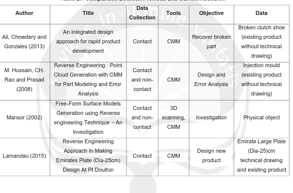
Figure 2.1. Coordinate Measuring Machine (CMM)
CMM consists of several main components interrelated and affect the accuracy of
the machine. The parts are:
a. Working table, a place of putting parts to be measured which is made of
granite.
b. Support, is the leg to prop up the entire burden of CMM. Some CMM is
furnished with air damper to reduce the vibration effects which produced by
the environment around the CMM.
c. Air bearing, CMM uses air bearing as a foundation to move for the entire axis.
d. Axis Guide ways, is the track of all axis to move, having direct contact with air
bearing. The average material made of aluminum, some of them also use
granite stones. For a machine with higher accuracy is using ceramic material.
e. Motor, is the main part to drive the axis specifically to the automatically
engine of just motorized using a joystick.
f. Joystick, is a control panel to facilitate the operators to operate machinery.
g. Controller, have various function: interface between pc and, motor driver as a
resources for the engine movement, data storage for storing correction files
or movement program of CMM, ADC, DAC, etc.
h. Probe head, works as a trigger for the CMM to record the touch point
position. Some CMM equipped with non-contact probe head to get touching
point that can reach hundreds or even thousands of points for the purposes of
CAD/CAM. We can not directly touch the part but through intermediaries
20
i. Sensors. CMM has many sensors to improve its accuracy. The sensors
include: temperature sensor, overcurrent sensor, limit switch, home position
sensor, air pressure sensor, reading head.
j. Linear scale. This unit is a transducer to change position to be a current or
voltage. Using the software converts it into coordinate data.
k. Software. A linker between the user and machine.
Currently the best result in terms of accuracy and surface quality is obtained
using contact system reverse engineering. It has the advantages of non-contact
system, which are:
1. Prevent unnecessary data retrieval because it can make the scan results into
a large memory.
2. The perpendicular view can be taken accurately.
3. The density of the data can not be determined automatically but manually and
we can take the data freely.
4. Tiny detail can be captured accurately.
Reverse engineering-based methods have been around forty years ago. The first
method of reverse engineering is Coordinate Measuring Machine (CMM). This is
a machine that can provide data in the form of 3D shape of the original object.
CMM measures the surface of an object using the contact probe, with a highly
sensitive pressure device. It will be activated if there is direct contact with the
object.
There are several types of CMM in determining accurate measurement, flexibility,
time of the measurement process, the maximum work piece dimensions scalable
and cost. Most types of CMM can be controlled manually by the operator or by a
program. CMM which is driven by the operator called Manual CMM, while driven
by a program called CNC CMM. The following are explanations of some CMM
types:
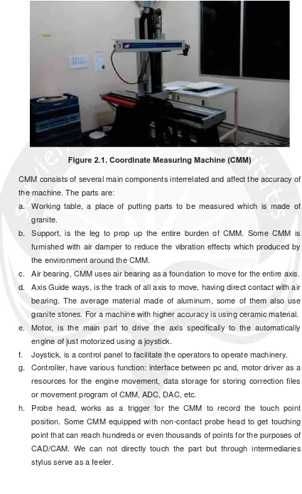
a. Bridge Type
For this type, the vertical arm (z-axis) is suspended vertically from a
horizontal beam that is supported by two vertical posts in a bridge
arrangement. The machine x-axis carries the bridge, which spans the object
to be measured. This type of CMM can have a smaller footprint which is
suitable for clear room or design laboratory type of facilities. Applications for
21
shape or varying (dies, metal, plastic, molds), inspection based of the points
on the object, continue inspection. Figure 2.4. is examples of bridge type
CMM.
Figure 2.2. CMM Bridge Type (Kamrani, 2006)
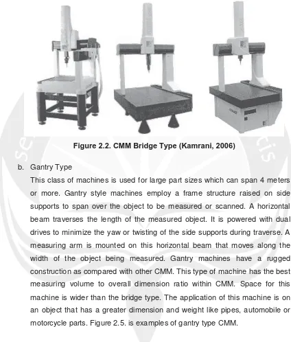
b. Gantry Type
This class of machines is used for large part sizes which can span 4 meters
or more. Gantry style machines employ a frame structure raised on side
supports to span over the object to be measured or scanned. A horizontal
beam traverses the length of the measured object. It is powered with dual
drives to minimize the yaw or twisting of the side supports during traverse. A
measuring arm is mounted on this horizontal beam that moves along the
width of the object being measured. Gantry machines have a rugged
construction as compared with other CMM. This type of machine has the best
measuring volume to overall dimension ratio within CMM. Space for this
machine is wider than the bridge type. The application of this machine is on
an object that has a greater dimension and weight like pipes, automobile or
22
Figure 2.3. CMM Gantry Type (Kamrani, 2006)
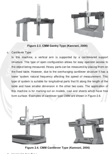
c. Cantilever Type
In this machine, a vertical arm is supported by a cantilevered support
structure. This type of open configuration allows for easy operator access to
the object being measured. Heavy parts can be measured by placing them on
the fixed table. However, due to the overhanging cantilever structure it has a
lower 'system natural frequency affecting the speed of measurement. This
type of system is suitable for longitudinal parts that fit along the length of the
table and have smaller dimension in the other two axes. The application of
this machine is for marking-out on models, cast and sheets which have free
form surface. Examples of cantilever type CMM are shown in Figure 2.6.
Figure 2.4. CMM Cantilever Type (Kamrani, 2006)
d. Horizontal Arm Type
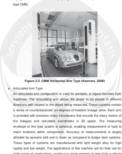
Horizontal arm machines are widely used in the automotive industry. In this
23
cantilevered from a movable vertical support. As a result, this style is
sometimes referred to as cantilever design. It is also available in dual arms.
The overhanging arms limit the dynamic stiffness of the machine affecting
speeds of measurements. The applications of this machine are for large
dimension components, measurement of free form body contour (automobile
styling and aircraft aero foil shape). Figure 2.7. is example of horizontal arm
type CMM.
Figure 2.5. CMM Horizontal Arm Type (Kamrani, 2006)
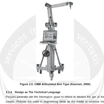
e. Articulated Arm Type
An articulated arm configuration is used for portable, or tripod mounted style
machines. The articulating arm allows the probe to be placed in different
directions with respect to the object being measured. These systems contain
a series of counterbalanced six-degrees-of-freedom linkage arms. Each arm
is provided with precision rotary transducers that encode the rotary motion of
the linkages and calculates coordinates in 3D space. The measuring
envelope of this type system is spherical, enabling measurement of hard to
reach locations within components. Accuracy of measurements is largely
affected by operator skill and is lower as compared to bridge style systems.
These types of systems are manufactured with light weight alloy for high
rigidity and low weight. The applications of this machine are for field use for
24
(auto styling, aero-wing, aero foil contour, etc). Figure 2.8. is example of
articulated arm type CMM.
Figure 2.6. CMM Articulated Arm Type (Kamrani, 2006)
2.3.4. Design as The Technical Language
Pictures generally are the information given to others to declare the aim of the
creator. Pictures are used in engineering fields as the media to continue the
information exactly and objectively, called as engineering language.
Information in the pictures can’t be written with sentences, but it must be given in
term of common symbols used in engineering language. The most important
thing for designer is the designer can give exact pictures consider to the reader.
For the reader, the most important thing in reading the pictures is how much
information that he/she can get.
In engineering language, pictures have many functions. Based on the group there
25
a. Arriving information
In arriving information, we have to consider about the readers of the pictures
because the people is not only from the company itself but sub-contract
people and foreign people that use different language. So the pictures have
standards as engineering language system for supporting enough rules.
Designers have to understand and notice this.
b. Keeping, lasting, and using information
In physical or non-physical project, we must have save able data as the
reference to make it better or for next project. In this case, pictures are one of
technical data that is effective where the technology of company is gotten and
collected. Pictures also can be used as information for new plans.
c. Methods of thinking in keeping the information
In planning a project’s concept, things in the mind can be formed in pictures
by analyzing and then the pictures are seen carefully and evaluated. To get
perfect result, this process needs to be done repeatedly.
In short term, drawing is not only an activity but drawing is used to enhance the
mindset in the planning. An engineering academia without drawing prosperity will
have less way in giving the important desires.
2.3.5. PowerSHAPE
PowerSHAPE is one of CAD software, product from Delcam. In powerSHAPE
there are basic modules functionality and several specialized such as: PS-Draft
(for making detail pictures), PS-Mold maker (for designing a mold), PS-Assembly
(for making assembly process model from solid form), PS-Render (for showing
pictures with good visual quality). (UAJY-Delcam Training Center, 2006)
Beside it, there are other instruments, these are the explanation:
1. Wireframe Modeling
This is used to make a model from surface and solid. Compare to the other
software, PowerSHAPE can give better wireframe in 2D or 3D model.
2. Surface Modeling
It has six standard primitive surfaces, there are: Plane, Box, Sphere, Cylinder,
Cone, and Torus. With standard primitive surfaces we don’t need to make
wireframe. Besides, the primitive surfaces’ shape or size can be edited and
26
3. Solid modeling
In solid modeling we can make pictures from solid primitive. A solid can be
made with joining some surfaces. A surface can be converted into solid.
4. Triangle modeling
It is very useful for editing a STL file. With triangle modeling we can modify
the shape and size freely.
In PowerSHAPE there are features to evaluate a CAD model before entering the
next step. These features are very useful to avoid defect in machining process.
After machining process sometimes there are unsmooth surfaces or unwanted
dents. The features are:
a. Models Contents List
The function is showing the amount of wireframe, curve, surface, and solid in
a model.
b. Toggle Surface Inspection Mode
Help to check the selected surface and leave the unselected surfaces.
c. Sectioning Dynamic
Help to make sectional view. It helps users to see the thickness or the
section result of the pictures.
d. Smoothness Shading
Help in checking the surface smoothness of a picture before entering the
machining process. It is noticed carefully by the company.
e. Undercut Shading
Help to check whether there is undercut part or unreachable surface in three
axis machine or not.
f. Curvature Shading
Show the curves of the model.
g. Minimum Radius Shading
Check the smallest radius in the model. It is very helpful in choosing the
milling cutter that will be used in machining.
h. Thickness Shading
27
i. Minimum Wall Thickness
It is a minimum wall thickness’ view in solid model.
j. Model Compare
Compare two different models.
PowerSHAPE can read or export file from other CAD software like AutoCAD,
IGS, ACIS, CATIA, Inventor, ArtCAM, Solidworks, and ProEngineer.
In PowerSHAPE, there is stencil feature. This feature helps user to make a
design from JPEG picture, then make lines based on JPEG picture. This process
is called tracing.
2.3.6. CMM Manager
CMM manager is one of software to run the CMM. This software can help users
in measuring and checking from the CAD model directly. Beside it, users can
simulate the measuring process to know there are any mistakes or not.
These are some of function in CMM Manager:
1. Walk-in Measurement
CMM Manager fully supports walk-in checking, includes the machine setting,
spot checking, fast dimension checking, and shows the checking report.
Fully integrated environment supplies complete measurement working room
to do some procedures, includes work piece’s reference setting and report
collecting point. Users can finish walk-in measurement in minutes with this
software.
2. Teaching a part program
In CMM application, a program is always created to record checking process
command, so can be executed or run for repeated working. For modern
manufacturing process, we very need program, so it doesn’t only guarantee
consistent checking but also make lower inspection time.
3. Running a part program
After making and saving program, CMM-Manager enables users to take the
finished program from the file and then run repeatedly to check the work
piece. It will give advantage for the users because CMM can check
automatically and consistently and minimize operator interaction in doing
28
4. Offline part programming
CMM-Manager provides ability in teaching programs when it breaks from
CMM itself in PC remote without CMM. The ability of offline program can
make the CMM users to do the duties of actual product inspection freely.
CMM-Manager calculates all needed parameters (measuring, checking,
probe combustion, and good probe angle). Simulating inspection helps in
program verification before doing CMM via online.
5. Graphical and test reporting
CMM-Manager has ability in reporting to visualize and make documentation
the checking result, make the report from CMM inspection result easily, fast,
and accurately.
6. Complete GD and T Tolerance reporting
CMM-Manager supports types of toleration in reporting. Every type contains
a method to decide the value of toleration default so it can reduce time
needed of the operator to make the report.
7. Reverse Engineering
Measuring result can directly export to standard CAD file, such as IGES and
DXF. Then it can be imported into CAD system that is used to achieve the
reverse engineering order. This ability makes the need of the manual
measurement tools disappear and avoids the non-accurate measurement.
In CMM-Manager there are some menus that help in scanning. There are:
a. Alignment Tab
This is used to reset the measured or checked parts that have moved
physically in CMM table. This can happen because of accident or because
priority production needs to check different part. This menu disables lost in
measurement previous data.
b. Features tab
In this menu there are some tools that are used for giving command to
measure, build fields, and edit.
c. Report tab
This menu sets the reporting the measurement result that has done.
d. Program tab
29
e. Probe tab
Set and edit probe
f. Import / export tab
To import and export file that already did before
g. System tab
It contains about system setting in CMM Manager.
h. Display tab
Set the view of CMM Manager
i. Graphical report tab
Show the measurement result and the dimension of the work piece that want