DEVELOPMENT OF BRAKE SYSTEM FOR REDUCED SCALE VEHICLE
SASITHARAN A/L YELLAPAN
This Report for partial fulfilment for
Bachelor of Mechanical Engineering (Design & Innovation) with honours
Faculty of Mechanical Engineering Universiti Teknikal Malaysia Melaka
ii
DECLARATION
“I hereby declare that the work in this report is my own except for summaries and quotations which have been duly acknowledge.”
iii
iv
ACKNOWLEDGEMENT
The success of this group project depends largely on the encouragement and guidelines of many others. I take this opportunity to express my gratitude to the people who have been instrumental in the successful completion of this report.
v
ABSTRACT
vi
ABSTRAK
vii
TABLE OF CONTENT
CHAPTER TITLE PAGE
DECLARATION II
ACKNOWLEDGEMENT IV
ABSTRACT V
ABSTRAK VI
TABLE OF CONTENT VII
LIST OF FIGURE X
LIST OF TABLE XIII
LIST OF SYMBOL XIV
LIST OF APPENDIX XV
CHAPTER I INTRODUCTION 1
1.0 Introduction 1
1.1 Background 1
1.2 Problem Statement 2
1.3 Objective 3
1.4 Scope 3
1.5 Thesis Outline 3
CHAPTER II LITERATURE REVIEW 4
viii 2.1 Multi-body Dynamics and Solution Method 4
2.1.1 MSC ADAMS 5
2.1.2 Universal Mechanism 6
2.1.3 Bond Graph Method 6
2.2 Brake System 11
2.2.1 Active Braking/ Differential Braking System 11 2.2.2 Conventional Braking System 12 2.2.3 Antilock Braking System (ABS) 13
2.2.4 Brake-By-Wire (BBW) 14
2.2.5 Electronic Brake System (EBS) 15
2.3 Scaled Vehicle 16
2.4 Control Strategies 17
2.4.1 PID Control 17
2.4.1.1 Ziegler-Nichols Method 18
2.4.1.2 Adaptive PID 19
2.4.1.3 Self-Tuning 20
2.4.2 Fuzzy Logic Control (FLC) 20
2.4.2.1 Components of FLC 21
CHAPTER III METHODOLOGY 23
3.0 Introduction 23
3.1 Flow Chart 23
3.2 Development of Brake Dynamics Model using Bond
Graph Method 25
3.3 Expension of Bond Graph to Block Diagram 32 3.4 Development of Brake Dynamics in Matlab/Simulink
Model 33
3.5 Torque Tracking Control 36
3.6 ABS Control Design by Simulation 38
3.6.1 Vehicle Modelling 39
CHAPTER IV RESULTS AND DISSCUSSION 44
ix 4.1 Simulation Results for ABS Braking 47
4.1.1 Wheel Slip 47
4.1.2Wheel and Vehicle Speed 49
4.1.3Braking Distance 51
CHAPTER V CONCLUSION AND RECOMENDATION 53
REFERENCES 55
x
LIST OF FIGURE
NO. TITLE PAGE
2.1 Process in bond graph. 7
2.2 Example of C elements 8
2.3 Example of I elements 8
2.4 Example of resistors 9
2.5 Example of modulated voltage source 9
2.6 Example of transformers 10
2.7 Example of gyrators 10
2.8 Degree of freedom for vehicle model for differential braking based
system 12
2.9 Hydraulic brake system 13
2.10 Brake-by-wire system components 15
2.11 FLC components 21
3.1 Project flow chart 24
3.2 Schematic diagram of brake system elements 25
3.3 Bond graph representation of the electromechanical brake system 27
3.4 Bond graph with the mechanism partition 27
xi 3.10 Construction of effort differences at 6th junction 30 3.11 Construction of effort differences at 7th junction 31
3.12 Motor and electric circuit schematic 31
3.13 Expansion of bonds to bilateral signal flows 32
3.14 Bond graph expended to block diagram 33
3.15 Block Diagram of Brake System 33
3.16 Brake dynamics model in Matlab/SIMULINK 35
3.17 General form block-diagram of torque tracking control 36 3.18 Simulink representation of torque tracking control using PID 37
3.19 Model of wheel with force signs 37
3.20 General form ABS control design for PID 38
3.21 General form ABS control design for Fuzzy 38
3.22 Quarter car vehicle longitudinal model 39
2.23 Coefficient friction versus slip 40
3.24 Simulation model of vehicle model 41
3.25 Simulation model of ABS design using PID 41
3.26 Simulation model of ABS design using FLC 42
4.1 Torque tracking performance for sinusoidal function 45 4.2 Torque tracking performance for square function 45 4.3 Torque tracking performance for saw-tooth function 46 4.4 Torque tracking performance for random function 46
4.5 Wheel slip graph using PID 47
4.6 Wheel slip graph using FLC 48
4.7 Comparison graph between FLC and PID for slip ratio 49
4.8 Wheel and vehicle speed graph using PID 50
4.9 Wheel and vehicle speed graph using FLC 50
4.10 Vehicle braking distance graph using PID 51
4.11 Vehicle braking distance graph using FLC 52
A1 Gantt chart for PSM 1 62
A2 Gantt chart for PSM 2 62
B1 FLC General setting 63
xii
xiii
LIST OF TABLE
NO TITLE PAGE
2.1 Bond graph elements 7
2.2 Z-N PID step response tuning parameters 18
2.3 Z-N PID frequency response tuning parameters 19
3.1 Effort and flow variable and component 26
3.2 Junctions 26
3.3 Brake system parameters (available and calculated) 34
3.4 Brake system parameters (not identified) 35
3.5 Membership function rules 42
xiv
LIST OF SYMBOL
x - Lateral velocity
y - Longitudinal velocity
- Yaw rate
fl
- Wheel velocity – front left
fr
- Wheel velocity – front right
rl
- Wheel velocity – rear left rr
- Wheel velocity – rear right u - Input voltage
- Motor arm angle
p
K - Proportional gain I
K - Integral gain
d
K - Derivative gain
- Torque
F - Force
v - Velocity
- Angular velocity
E - Young modulus
m - Mass
I - Inertia
- Slip
xv
LIST OF APPENDIX
NO TITLE PAGE
A Gantt chart 62
1
CHAPTER I
INTRODUCTION
1.0 INTRODUCTION
This chapter describes the background about development of brake system for reduced scale vehicle. The problem statement that proposed to the development of this project is explained. Next, by the objective and scope of the project were covered.
1.1 BACKGROUND
2 is unable to steer the car once the wheel is fully locked up which lastly will result in skidding, increased braking distance and loss control. So for the emergency braking, the momentary wheel rotation is required. ABS helps in pumping and releasing the brakes automatically whenever required. ABS can prevent cars or SUVs from skidding during braking. Moreover, ABS allows the driver to stop a vehicle more rapidly and maintain steering control even during situations of panic. Brake-by-wire is a new technology that implemented in the field of vehicles active safety. This system uses a motor to transmit the braking force by eliminating the conventional hydraulic braking system in order to improve the response speed and increase braking performance. Moreover, this system helps to reduce the time taken for assembly and maintenance which usually consumes a lot of time in the conventional braking system. Brake-by-wire system promises to increase the safety and cuts off cost related to manufacturing and maintenance. This braking system is concerned as most important in every vehicle where its improved efficiency and stability of brake control.
1.2 PROBLEM STATEMENT
3 scale vehicle testing is its ability to push the vehicle to its handling limits in order to evaluate the performance, which would otherwise be too dangerous for traditional full scale vehicle testing.
1.3 OBJECTIVE
The objective of this project is to develop reduced scale vehicle dynamics model. Besides that to develop Antilock Braking System (ABS) control scheme using PID and fuzzy logic control.
1.4 SCOPE
The scope of this project covers the development of brake dynamics model in Matlab/SIMULINK environment. Besides that, there will be development of brake torque tracking control using PID controller. Lastly, the development of Antilock Braking System (ABS) for reduced scale vehicle using PID and fuzzy logic control.
1.5 THESIS OUTLINE
4
CHAPTER II
LITERATURE REVIEW
2.0 INTRODUCTION
This chapter covers the literatures of brake system that's available in markets. Besides that, the control strategies are also discussed. Moreover, the Bond Graph Method, MSC ADAMS software and Universal Mechanism multi body software also reviewed in detail.
2.1 MULTI-BODY DYNAMICS AND SOLUTION METHOD
5 motion is must needed part when analysing the dynamic response of the multi-body system and can derived using global or topological formulations.
2.1.1 MSC ADAMS
There are a lot of software packages available to solve multi-body system analysis. Adams is one of the famous multi-body dynamic software which use to make motion analysis too. Blundell (2004) noted that software has become one of the mediums for engineers to do their task in an easy way to study the dynamics of moving parts and forces distributed through mechanical system. Autoun et al. (2002) stated that the large usage of the MSC ADAMS in automotive industry is to study the suspensions or to study the ride and handling performance of the vehicle.
“Build and test” is a traditional way to get findings on the multi-body problems. This method is much expensive and at certain times it is impossible to get the results. MSC ADAMS software helps engineers to create a virtual prototype of mechanical systems in a short period of time and in lower cost to test it. This software is able to solve the physics of the system together with the equation for kinematics, statics, dynamics and quasi-statics.
6 2.1.2 Universal Mechanism
Universal Mechanism (UM) is a software which intended for simulation of kinematics and dynamics of planar and spatial mechanical systems. UM said to be an advanced postprocessor which includes the linear analysis, statistics, multi-variant calculation and optimization and export of results. Universal Mechanism (2012) stated that this software able to solve both direct and inverse kinematic, dynamic and control problems. As an advantage UM can load any of the body shapes and automatically calculate inertia parameters of the system that inserted. The joints and constraints that can be applied using UM is rotational, translational, cylindrical, gimbal, general and quaternion joints. Besides that, forces available to do fix is general, bipolar, contact and special. As the key point where the measurable parameters are reaction forces and moments and other normal parameters such as linear and angular coordinates, velocities and acceleration.
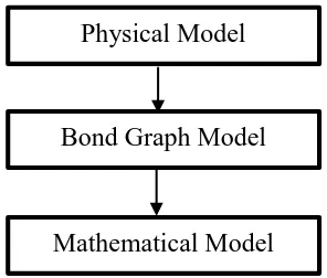
2.1.3 Bond Graph Method
7
Figure 2.1: Process in bond graph.
Liming (2012) stated that nowadays there are a number of software available to generate and process bond graphs which have a capability to generating of symbolic representation, model inversion, and parametric identification and also produce simulation. The bond graph elements are drawn as latter combinations indicating the type of element. The bond graph elements are in Table 2.1.
Table 2.1: Bond graph elements Elements Description
C Storage element for a q-type variable I Storage element for a p-type variable R Resistor dissipating free energy
Se, Sf Sources
TF Transformer
GY Gyrator
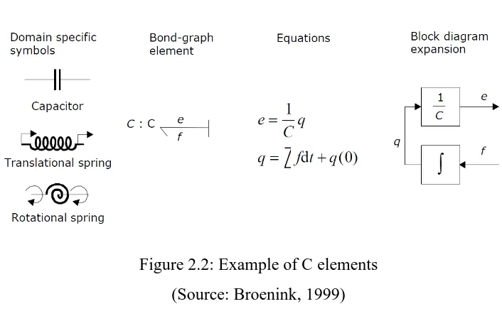
Figure 2.2 shows the examples of C-elements are given with equivalent block diagram. For the capasitor, C is the capacitance and for spring, K is the stiffness and C the compliance.
Physical Model
Bond Graph Model
8
Figure 2.2: Example of C elements (Source: Broenink, 1999)
Figure 2.3 shows the examples of I-elements are given with equivalent block diagram. For the inductor, L is the inductance and for mass, m is the mass.
Figure 2.3: Example of I elements (Source: Broenink, 1999)
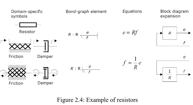
9
Figure 2.4: Example of resistors (Source: Broenink, 1999)
Figure 2.5 shows the modulated source driven by some signal form and the standard symbols for that source.